When to Use Ceramic vs Electrolytic Capacitors: The Four Factors the Simple Rules Leave Out
The simplified rule most electronics courses teach is: use ceramic capacitors for high-frequency decoupling and bypass, use electrolytic capacitors for bulk energy storage and low-frequency filtering. This rule is directionally correct and works for a surprising number of applications. It also fails in ways that are frustrating to diagnose because the failure is not a wrong component value — it is a wrong component type that appears to have the right value.
Here are two examples where the simple rule breaks down:
A designer places a 10 µF X5R ceramic capacitor on a 5V rail to replace two 4.7 µF electrolytics and reduce BOM count. The circuit works in bench testing. In production, units built during cold ambient temperatures ship with intermittent reset behavior. The cause: the X5R dielectric's capacitance drops significantly at low temperature and under DC bias simultaneously. At 5V DC bias and −20°C, that 10 µF capacitor may be delivering 3–4 µF — less than one of the electrolytics it replaced. The nominal value on the component label is essentially meaningless without knowing the operating conditions.
A different designer replaces a 100 µF electrolytic in a linear regulator output stage with a 100 µF polymer aluminum capacitor for better ripple handling. The polymer has lower ESR, which should be an improvement. Instead, the regulator oscillates. The reason: the linear regulator's stability compensation network was designed assuming a specific minimum ESR at the output — the higher ESR of the electrolytic was contributing a zero to the loop transfer function that kept the phase margin adequate. The "better" capacitor destabilized the circuit.
Both of these failures trace back to the same underlying issue: capacitor selection is not about choosing between two interchangeable options with different packaging. It is about understanding four physical characteristics — ESR, ESL, voltage coefficient, and temperature coefficient — and matching them to what the circuit actually needs. The simple rule only works when those four factors happen not to matter. In many modern circuits, they do.
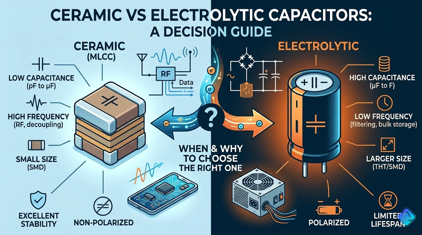
1.0 What the Two Technologies Actually Are
Ceramic capacitors (MLCC — Multi-Layer Ceramic Capacitor):
A ceramic capacitor stores charge by polarizing a ceramic dielectric material between metal electrode layers. The capacitance is determined by the dielectric material's permittivity (ε), the electrode area, and the distance between layers. Modern MLCCs stack hundreds of thin dielectric layers with interleaved electrodes in a compact surface-mount package.
The critical feature of ceramic capacitors: they have no electrolytic chemistry, no liquid or gel electrolyte, and no polarity requirement. They are inherently non-polar — a ceramic capacitor can be connected in either orientation with no damage or performance change. They have extremely low equivalent series resistance (ESR), typically in the milliohm range, and extremely low equivalent series inductance (ESL), making them effective at high frequencies.
The critical limitation: the ceramic dielectric's permittivity changes with applied voltage and temperature in ways that substantially reduce the actual capacitance from the labeled nominal value.
Electrolytic capacitors (aluminum electrolytic):
An aluminum electrolytic capacitor uses a thin aluminum oxide layer grown on etched aluminum foil as the dielectric. The oxide layer is extremely thin — a few nanometers — allowing very high capacitance in a small volume. A liquid electrolyte (which is conductive and completes the electrical circuit between the oxide dielectric and the counter-electrode) fills the space between the foil layers.
The critical feature: the oxide layer can be made extremely thin, yielding very high capacitance-per-unit-volume and low cost per microfarad. A 1,000 µF aluminum electrolytic fits in a package the size of a pencil eraser; a 1,000 µF ceramic capacitor at equivalent voltage rating would be impractically large.
The critical limitations: aluminum electrolytics are polar (the positive terminal must be connected to the higher potential, or the oxide layer is damaged); they have significantly higher ESR than ceramics; they have finite life limited by electrolyte evaporation (typically 2,000–10,000 hours at rated temperature); and they contain a liquid that can leak if the capacitor is damaged or operated outside its ratings.
2.0 The Four Factors That Actually Determine the Choice
Factor 1: ESR (Equivalent Series Resistance)
Every real capacitor has series resistance from its leads, electrodes, and electrolyte (if present). This resistance dissipates power when current flows through the capacitor — as heat in the component — and creates a voltage drop proportional to current. In filtering applications, the ESR limits how effectively the capacitor can suppress ripple current from a power supply or switching converter.
Typical ESR values:
- C0G/NP0 ceramic: 0.01–0.1 Ω (milliohm range)
- X5R/X7R ceramic: 0.01–0.05 Ω
- Aluminum electrolytic: 0.05–5 Ω (much higher, especially at low temperatures)
- Polymer aluminum: 0.005–0.05 Ω (low ESR, approaching ceramic)
- Tantalum (conventional): 0.1–2 Ω
For high-frequency applications (> 1 MHz), even small ESR differences matter significantly because the ripple current is large and high-frequency.
Factor 2: ESL (Equivalent Series Inductance)
Physical capacitors also have lead and package inductance. Above a certain frequency (the self-resonant frequency), this inductance dominates and the component behaves as an inductor, not a capacitor. Above self-resonance, adding a "larger" capacitor paradoxically worsens high-frequency filtering because the larger package has more parasitic inductance.
Typical ESL and self-resonant frequency:
- 0402 ceramic 100 nF: ESL ≈ 0.5 nH, SRF ≈ 225 MHz
- 0805 ceramic 100 nF: ESL ≈ 1 nH, SRF ≈ 160 MHz
- 100 µF electrolytic (radial): ESL ≈ 10–20 nH, SRF ≈ 1–5 MHz
- 100 µF polymer (SMD): ESL ≈ 2–5 nH, SRF ≈ 5–15 MHz
For decoupling a 200 MHz processor, a large electrolytic provides essentially no filtering at the operating frequency — its self-resonant frequency is far below the noise frequency. Small ceramic capacitors with low ESL are required.
Factor 3: Voltage Coefficient (the one most engineers underestimate)
Class II ceramic dielectrics (X5R, X7R, X8R, Y5V) exhibit a capacitance decrease under applied DC voltage. This is called the DC bias effect. The magnitude varies dramatically by dielectric class and package size. A 10 µF 0402 X5R ceramic at its rated voltage may deliver only 20–30% of its nominal capacitance. This effect compounds with temperature.
Practical example: a 10 µF X5R 0402 16V capacitor measured at 5V DC bias: effective capacitance drops to approximately 5–6 µF. The same 10 µF X7R 0805 at 5V: approximately 7–8 µF. The voltage coefficient is why "100 nF bypass capacitors" should use C0G/NP0 dielectric for precision analog circuits — C0G has essentially zero voltage coefficient.
Factor 4: Temperature Coefficient
Ceramic dielectric codes encode their temperature stability:
- C0G/NP0: ±30 ppm/°C across −55°C to +125°C. Essentially flat. Best for precision timing, filters, RF circuits.
- X5R: ±15% from −55°C to +85°C. Moderate stability. Suitable for bypass and decoupling.
- X7R: ±15% from −55°C to +125°C. Same tolerance, wider range.
- Y5V: +22% to −82% from −30°C to +85°C. Nearly useless for precision. Almost never appropriate for new designs.
Aluminum electrolytics typically change ±20% from their nominal value across their temperature range, with the most significant changes at low temperature where the electrolyte viscosity increases (raising ESR dramatically — sometimes 5–10× the room temperature value at −40°C).
3.0 The Math: Impedance, ESR, and Why It Matters at Frequency
The total impedance of a real capacitor at a given frequency is:
Z = √(ESR² + (X_L − X_C)²)
Where:
- X_C = 1/(2π × f × C) = capacitive reactance (decreases with frequency)
- X_L = 2π × f × L = inductive reactance from ESL (increases with frequency)
- ESR = series resistance (approximately constant with frequency)
At low frequencies (well below self-resonance): Z ≈ X_C = 1/(2πfC). The capacitor behaves as a pure capacitor, and a larger C gives lower impedance. An electrolytic's high capacitance value wins here.
At self-resonant frequency: X_C = X_L, and Z = ESR. This is the minimum impedance point — where the capacitor works best as a filter. This is why choosing a capacitor based on SRF near your noise frequency is important.
Above self-resonance: X_L dominates and Z increases with frequency. The component is now an inductor, not a capacitor. Adding a "bigger" capacitor with a lower SRF makes things worse, not better.
Worked example — 100 nF 0402 X5R ceramic bypass:
At 100 MHz: X_C = 1/(2π × 10⁸ × 10⁻⁷) = 15.9 mΩ ESL-based reactance: X_L = 2π × 10⁸ × 0.5 × 10⁻⁹ = 314 mΩ Since X_L > X_C at 100 MHz, this capacitor is above its self-resonant frequency and acts more like an inductor than a capacitor at 100 MHz. Use a smaller package (0201) or a lower-value capacitor (10 nF or 1 nF) for 100 MHz bypassing.
Why parallel capacitors improve performance:
Placing a small ceramic (e.g., 100 nF) in parallel with a large electrolytic (e.g., 100 µF) covers different frequency ranges:
- The electrolytic handles 0–5 MHz range (bulk energy, low-frequency ripple)
- The ceramic handles the 5 MHz–500 MHz range (high-frequency decoupling) Together, they provide low impedance across a broad spectrum. Neither alone covers both ranges adequately.
4.0 Real Circuit Applications: Which Type to Use and Why
Application 1: IC power supply decoupling (100 nF bypass)
Use: C0G or X7R ceramic, 100 nF, smallest available package (0402 or 0201)
Reason: The purpose is to suppress high-frequency current spikes from the IC's switching logic. The frequencies of concern are 10 MHz to 1 GHz. Electrolytic capacitors are self-resonant below 10 MHz for any practical value — they provide zero high-frequency filtering. A ceramic's low ESR and low ESL, combined with placement directly adjacent to the IC's power pins, provides the low-impedance path that absorbs switching transients before they propagate to the power supply.
Application 2: Bulk energy storage on power supply output (100–470 µF)
Use: Aluminum electrolytic or polymer aluminum, sized by ripple current rating
Reason: The power supply output needs bulk energy storage to handle large, slow current demands (like an MCU waking up and loading the bus, or a motor starting). The required capacitance (100–470 µF or more) is impractical in ceramic at reasonable size and cost. An electrolytic at 47–100 µF in combination with a 10 µF ceramic is the common approach.
Application 3: Precision analog filter capacitor
Use: C0G/NP0 ceramic, sized exactly to the circuit design
Reason: Analog filters, timing circuits, and precision integrators require that capacitance does not change with voltage, temperature, or time. C0G's near-zero voltage coefficient and ±30 ppm/°C temperature coefficient make it the only ceramic option acceptable here. X7R and X5R would introduce signal-dependent distortion (because the capacitance changes with the signal voltage across it) that would be audible in audio circuits or visible as frequency drift in timing circuits.
Application 4: Input filter capacitor for switching regulator (bulk + high-frequency)
Use: Large electrolytic (100–470 µF) in parallel with 1–10 µF X7R ceramic
Reason: The electrolytic provides bulk energy storage to prevent large voltage droops when the regulator switches. The ceramic handles the high-frequency ripple current harmonics that are above the electrolytic's self-resonant frequency. Without the ceramic, high-frequency ripple passes through to the input supply. Without the electrolytic, the input voltage dips unacceptably during the switching cycle.
Application 5: AC coupling in audio signal paths
Use: Film capacitor (polyester or polypropylene), or C0G ceramic for small values
Reason: Audio signals are sensitive to distortion introduced by voltage-dependent capacitance. Class II ceramics (X5R, X7R) change capacitance with the AC signal voltage, creating harmonic distortion that is audible — especially at bass frequencies where the voltage swing is larger. Film capacitors have essentially zero voltage coefficient and are the traditional choice for audio coupling. C0G ceramics are acceptable for small coupling values (< 1 nF). Never use X5R or X7R for audio coupling or precision signal path applications.
5.0 Five Misconceptions That Lead to Wrong Capacitor Selection
Misconception 1: "A 10 µF ceramic can directly replace two 4.7 µF electrolytics"
As described in the introduction, this substitution fails when the ceramic's DC bias derating reduces the effective capacitance significantly below 10 µF at the operating voltage. Before substituting ceramic for electrolytic on any supply rail above a few volts, simulate the effective capacitance at the DC operating voltage using the manufacturer's capacitance-vs-voltage characteristic curve (available in their online SPICE model or product page tools). A 10 µF 0402 X5R rated at 10V, used on a 5V rail, may deliver 4–5 µF effective — less than one of the electrolytics it replaced.
Misconception 2: "Lower ESR is always better"
The linear regulator instability example from the introduction illustrates this. Many older linear regulator designs (LM317, LM2940, and similar devices) use the output capacitor's ESR as part of their compensation network. The datasheet specifies a minimum ESR (typically 0.1–1 Ω) in addition to a minimum capacitance. Installing a low-ESR polymer or ceramic capacitor without checking the regulator's stability requirements can remove a compensation zero and cause oscillation. Always check the regulator's ESR specification before substituting a low-ESR capacitor type.
Misconception 3: "The capacitor value on the component label is the capacitance in the circuit"
For C0G and film capacitors, this is approximately true over most operating conditions. For Class II ceramics (X5R, X7R, Y5V), the labeled value is measured at 1 kHz, 0V DC bias, at room temperature — conditions that rarely describe actual circuit operation. Under realistic DC bias and temperature, effective capacitance can be 20–70% of the labeled value. This is not a defect or a manufacturing variation; it is the designed behavior of the dielectric. The solution is to select components based on effective capacitance at operating conditions, not nominal capacitance at test conditions.
Misconception 4: "Large electrolytics are always needed for low-frequency filtering; ceramics are for high frequency only"
Modern high-value ceramic capacitors (47 µF to 100 µF in X5R or X7R) are available in larger packages and are used in applications previously served by electrolytics — including low-frequency power supply filtering. The trade-off is cost (ceramics at 100 µF are more expensive than equivalent electrolytics) and the DC bias derating issue. In space-constrained, high-reliability, or high-temperature applications where electrolytic life is a concern, large-value ceramics are a legitimate choice if the voltage coefficient effect is accounted for. The frequency domain is not the only valid way to choose between the types.
Misconception 5: "Y5V ceramic is suitable if the temperature range is mild"
Y5V dielectric has a capacitance tolerance of +22% to −82% across its rated temperature range. Even in a controlled room temperature environment (say, 20–30°C), Y5V capacitors exhibit large capacitance variation with DC bias — the voltage coefficient effect is severe in Y5V. At typical operating voltages, a Y5V capacitor may deliver 10–30% of its nominal capacitance. Y5V components should not be used in any application where capacitance value matters. They were historically used as cheap bypasses in applications where any capacitance was better than none, but even in that use case, X7R provides far more predictable behavior at modest additional cost. Y5V is essentially never the correct choice in a new design.
6.0 Practice Problems: Test Your Understanding
Problem 1: A 3.3V LDO requires an output capacitor of 1–10 µF with ESR of 0.05–10 Ω for stability. You have a 10 µF X5R 0402 ceramic (ESR < 0.01 Ω) and a 10 µF tantalum (ESR ≈ 1 Ω). Which is acceptable? (Answer: tantalum meets the ESR requirement; the ceramic's sub-10 mΩ ESR is below the specified minimum and may cause instability — check the datasheet's stability region diagram for your specific LDO)
Problem 2: You need a 100 nF bypass capacitor for a 1 GHz RF IC. You have 0805 100 nF X7R and 0402 100 nF X7R in stock. Which provides better 1 GHz bypassing? (Answer: 0402 — smaller package = lower ESL = higher self-resonant frequency = better performance at 1 GHz; the 0805 is likely self-resonant below 1 GHz)
Problem 3: A precision RC oscillator circuit requires a timing capacitor with 1% accuracy that must hold its value from −20°C to +70°C. Should you use X7R or C0G? (Answer: C0G — ±30 ppm/°C temperature coefficient gives < 0.3% change from −20°C to +70°C. X7R's ±15% change over its range could shift oscillation frequency by several percent.)
7.0 Real Questions from Circuit Designers
Q: I replaced the 100 µF electrolytic on my LM317 output with a 100 µF polymer capacitor for better ripple current handling. The regulator now oscillates. What happened?
A: Exactly the scenario described earlier. The LM317's stability requires the output capacitor to have ESR in a specific range — typically 0.1 Ω to 5 Ω. The polymer capacitor has ESR in the 0.01–0.05 Ω range, which falls below the minimum. The LM317's compensation relies on the ESR zero (a frequency at which the capacitor's impedance is dominated by its ESR rather than capacitive reactance) to maintain phase margin. With ESR too low, this zero moves to too high a frequency and the feedback loop's phase margin collapses. Fix: add a small series resistor (0.1–0.5 Ω) in series with the polymer capacitor to bring the effective ESR back into range, or use an aluminum electrolytic that naturally provides the required ESR, or use an LDO designed for stable operation with low-ESR ceramic outputs.
Q: For a 5V to 3.3V buck converter, the datasheet says the output needs 22 µF. I want to use two 10 µF 0805 X5R ceramics in parallel. Will that be enough?
A: Depends on the voltage rating of the ceramics. With 3.3V output, use X5R ceramics rated at least 6.3V (preferably 10V). A 10 µF 6.3V 0805 X5R at 3.3V operating voltage typically delivers approximately 7–8 µF effective after DC bias derating. Two in parallel give approximately 14–16 µF effective. If the converter requires 22 µF minimum for stability, this may be marginal. Check the specific product's capacitance-vs-voltage curve. Using 10V or 16V-rated ceramics (which have less derating at 3.3V) or using three 10 µF ceramics provides more reliable margin. Many modern buck converter datasheets specifically address effective capacitance derating and some recommend adding 50–100% extra nominal capacitance to account for it.
Q: Can I use X7R ceramic capacitors for audio signal coupling instead of film capacitors?
A: Not recommended for quality audio circuits. X7R ceramics have a non-linear voltage coefficient — as the AC signal voltage varies across the capacitor, the capacitance changes slightly with the instantaneous voltage. This creates a non-linear distortion mechanism. In an audio coupling capacitor, where the full signal swing appears across the capacitor, this non-linearity generates harmonic distortion — particularly second and third harmonics — that can be audible as "muddy" or distorted bass. Film capacitors (polyester for general coupling, polypropylene for higher quality) have essentially zero voltage coefficient and are standard for audio coupling. For signal levels below 100 mV (pre-amp input stages, small-signal processing), the X7R's distortion may be below audible threshold — but for line-level or power-level coupling, film is the correct choice.
8.0 Quick Reference Card
The Four Factors Summary:
| Factor | Ceramic (C0G) | Ceramic (X5R/X7R) | Aluminum Electrolytic | Polymer |
|---|---|---|---|---|
| ESR | < 0.05 Ω | < 0.05 Ω | 0.1–5 Ω | 0.005–0.05 Ω |
| ESL | 0.5–2 nH | 0.5–2 nH | 5–20 nH | 2–5 nH |
| Voltage coefficient | ≈ 0% | −20% to −70% at rated V | ≈ 0% | ≈ 0% |
| Temp coefficient | ±30 ppm/°C | ±15% | ±20% | ±10% |
| Polar | No | No | Yes | Yes |
| Max practical value | ~100 µF (large pkg) | ~100 µF | 10,000 µF+ | ~1,000 µF |
Application Decision Matrix:
| Application | Best choice | Why |
|---|---|---|
| IC bypass/decoupling (HF) | C0G or X7R ceramic, 100nF | Low ESL, low ESR, SRF > noise freq |
| Bulk supply storage | Aluminum electrolytic + ceramic | High capacitance + HF coverage |
| Precision timing/filter | C0G ceramic | Zero voltage/temp coefficient |
| Audio signal coupling | Film (polyester/polypropylene) | Zero voltage-dependent distortion |
| Low-ESR LDO output | Electrolytic (check ESR range) | Must meet minimum ESR for stability |
| High-temp > 85°C long life | Polymer or C0G ceramic | No electrolyte to evaporate |
| Large value, space-constrained | Polymer aluminum | Better than electrolytic, smaller |
The Dielectric Code Cheat Sheet:
| Code | Temp range | Capacitance tolerance | Voltage coefficient | Use for |
|---|---|---|---|---|
| C0G / NP0 | −55°C to +125°C | ±30 ppm/°C | ≈ 0% | Precision, RF, timing, audio |
| X5R | −55°C to +85°C | ±15% | Moderate derating | General bypass/decoupling |
| X7R | −55°C to +125°C | ±15% | Moderate derating | General bypass, wider temp |
| Y5V | −30°C to +85°C | +22%/−82% | Severe derating | Avoid in new designs |
The critical rule ESR manufacturers hide: For Class II ceramics (X5R, X7R), the effective capacitance at your DC operating voltage is typically 40–80% of the nominal value. Always check the vendor's SPICE model or online tool for the actual effective value at your operating conditions.

Written by Jack Elliott from AIChipLink.
AIChipLink, one of the fastest-growing global independent electronic components distributors in the world, offers millions of products from thousands of manufacturers, and many of our in-stock parts is available to ship same day.
We mainly source and distribute integrated circuit (IC) products of brands such as Broadcom, Microchip, Texas Instruments, Infineon, NXP, Analog Devices, Qualcomm, Intel, etc., which are widely used in communication & network, telecom, industrial control, new energy and automotive electronics.
Empowered by AI, Linked to the Future. Get started on AIChipLink and submit your RFQ online today!
Frequently Asked Questions
Can a ceramic capacitor replace an electrolytic capacitor directly?
Not always. Even with the same labeled value, ceramics often lose capacitance under DC bias and have much lower ESR, which can affect regulator stability. Always check effective capacitance, ESR requirements, and operating voltage before replacing one with the other.
Why are ceramic capacitors better for decoupling?
Ceramic capacitors have very low ESR and ESL, making them ideal for high-frequency noise suppression near IC power pins. Electrolytics are too inductive at high frequencies and are better suited for bulk filtering.
Why can low-ESR capacitors cause LDO instability?
Some regulators require a minimum ESR for stable operation. Replacing an electrolytic with a low-ESR ceramic or polymer capacitor can remove that stability margin and cause oscillation.
Is X7R suitable for precision analog or audio circuits?
Usually no. X7R changes capacitance with voltage and temperature, which can introduce distortion and drift. C0G/NP0 or film capacitors are better for precision timing, filters, and audio paths.
Should Y5V ceramic capacitors be avoided?
In most new designs, yes. Y5V has severe capacitance loss with voltage and temperature, making its real performance unpredictable. X7R is usually a much safer and more reliable choice.