When you look at a circuit diagram, you see a resistor symbol. It is a simple shape. It stands for an important electronic part. This symbol shows where a resistor goes on a schematic and on a PCB. You need to know resistor symbols to choose the right parts. You also need them to put parts in the right place. If you learn the rules and different types, you can read and make good electronic designs. This helps you avoid mistakes.
-
Knowing resistor symbols helps you:
-
Pick the right resistor for each place in your design.
-
Put resistors in the correct spot so your circuit works.
-
Follow the diagram, which makes building and fixing easier.
-
Resistor Symbols Explained teaches you how to spot, understand, and use resistor symbols in your projects.
Key Takeaways
-
Knowing resistor symbols helps you pick the right parts for your project.
-
Each resistor symbol shows its type and what it does. This helps you not make mistakes when building circuits.
-
Learn about IEC and IEEE standards. These help you read resistor symbols the right way.
-
Keep a resistor symbols chart nearby. It helps you find resistor types and values fast when you work.
-
Always look at the resistor’s value and type before you use it. This makes sure your circuit works well.
Resistor Symbols Explained
What Does a Resistor Do
Resistors are in almost every electronic circuit. They help devices work safely and well. If you ask, "what does a resistor do," you find out resistors control current in a circuit. They protect sensitive parts and keep things working right.
Resistor symbols in textbooks show how resistors manage electricity. Here are the main jobs of resistors in circuits:
-
Resistors control current flow, measured in ohms.
-
You use resistors to lower current and protect other parts.
-
Resistors keep current safe for things like LEDs.
If you know resistor symbols, you see how each resistor changes your circuit. You can pick better parts and avoid problems.
Resistor Symbol Basics
You see resistor symbols in every circuit diagram. These symbols show where each resistor goes and what kind you need. There are different shapes for resistor symbols, but they all mean a part that slows down electricity.
Resistor symbols look like zigzag lines or rectangles. You use these shapes for fixed resistors, variable resistors, and preset resistors. Here is how resistor symbols look in diagrams:
-
Zigzag lines or squiggles are for regular resistor symbols.
-
Rectangles with wires show fixed resistors with one value.
-
Rectangles with a slanted arrow show variable resistors you can change.
-
Preset resistors use a rectangle and an extra slanted line or arrow to show they change sometimes.
Resistor symbols follow international rules. Two big groups make these rules. The IEC uses a rectangle for easy reading. The IEEE uses a zigzag line, which many people know from old books. Here is a table that shows the official meanings:
| Standard | Resistor Symbol Description | Adoption and Usage |
|---|---|---|
| IEC 60617 | Rectangle shape for resistors, made for easy reading and matching. | Used a lot in Europe and other places, helps make diagrams clear. |
| IEEE Std 315-1975 | Zigzag or squiggle line for resistors, shows the old way. | Common in the U.S. and schools, known by engineers who learned older rules. |
When you read resistor symbols in diagrams, you match each symbol to the right part. This helps you build circuits and design PCBs. You make sure every resistor does its job and works right.
Tip: Always check which rules your diagram uses. This helps you pick the right resistor and not get mixed up.
You see resistor symbols in many styles, but the goal is the same. You use resistor symbols to show where resistors go and how they work in your design.
Resistor Symbol Standards
IEC vs. ANSI
There are two main standards for resistor symbols. The IEC 60617 standard uses a rectangle shape. The ANSI Y32 standard uses a zigzag line. Both symbols show where a resistor goes in your circuit.
Here is a quick comparison:
| Standard | Resistor Symbol Description |
|---|---|
| IEC 60617 | Simple outlined rectangle |
| ANSI Y32.2-1975 | 'Squiggle' styled line segments |
Different places used their own symbol styles. This made reading diagrams from other places hard. Groups like IEC and ANSI made global rules. Now, you can use these symbols anywhere. The IEC 60617 standard has thousands of symbols for electrical parts. You see it in schools, offices, factories, and repair shops.
Tip: Always check which standard your diagram uses. This helps you avoid mistakes and makes your work easier.
Symbol Variations
Modern circuit diagrams have many types of resistors. Each type has its own symbol. The symbol tells you what kind of resistor you need.
Here is a table showing common symbol variations:
| Resistor Type | Symbol Description |
|---|---|
| Fixed Resistors | Rectangle with leads; sometimes a zigzag line is used. |
| Variable Resistors | Rectangle with a diagonal arrow showing you can adjust it. |
| Preset Resistors | Fixed resistor symbol plus an extra diagonal line or arrow. |
| Potentiometers | Rectangle with three lines; an arrow shows the adjustable feature. |
| Specialized Resistors | Unique symbols for special roles beyond current regulation. |
You use these symbols to pick the right resistor. A rectangle with an arrow means it is a variable resistor. A zigzag line means it might be a fixed resistor. Specialized resistors have their own symbols. This helps you tell them apart.
You see these symbols in books, software, and on real circuit boards. Learning these symbols helps you read diagrams and build circuits with confidence.
Common Resistor Symbols
Fixed Resistor Symbol
Fixed resistor symbols are in almost every circuit diagram. These symbols show where a resistor controls the current. There are two main standards for these symbols. The IEC standard uses a rectangle shape. The ANSI standard uses a zigzag line shape. Both symbols mean the same thing, but they look different.
Here is a table that shows how the symbols look:
| Standard | Resistor Symbol |
|---|---|
| IEC | |
| ANSI |
You see letters like 'R', 'RN', and 'RF' next to these symbols. These letters tell you what kind of resistor you need. The table below explains what each letter means:
| Notation | Description |
|---|---|
| R | Fixed resistor |
| RN | Specific type of fixed resistor |
| RF | Variation of fixed resistor |
| FS | Potentially a specific type or designation |
You also see the Ω symbol. This symbol stands for ohms. Ohms are the unit for resistance. You use this symbol to read the value of each resistor in your diagram.
When you look at a fixed resistor symbol, you see two lines at each end. These lines show where you connect the resistor in your circuit. The rectangle or zigzag sits between the lines. You match the symbol to the right part when you build your project.
Tip: Always check the letters and symbols in your diagram. This helps you pick the correct resistor and avoid mistakes.
Variable Resistor Symbol
Variable resistor symbols show you where you can change resistance in your circuit. You spot these symbols by looking for an arrow. The arrow goes across the resistor symbol. This means you can adjust the resistance.
Potentiometers are a type of variable resistor. Their symbols have three pins. You see a rectangle with three lines coming out. The arrow points to the middle line. Older diagrams may show only two pins. Most modern ones use three pins.
When you use a variable resistor, you control how much current flows. You turn a knob or move a lever to change the resistance. The symbol helps you find this part in your diagram.
Note: The arrow in the symbol always means you can adjust the resistor. Look for this feature when you read circuit diagrams.
Specialized Resistor Symbols
Some resistors do more than just control current. Specialized resistor symbols help you spot these parts. You see symbols for photoresistors, fusible resistors, and more.
-
The photoresistor changes resistance when light hits it. You see the symbol "RL" next to it. This tells you the resistor reacts to light.
-
Photoresistors have pins that are not in order. You can use them easily in your design.
-
Fusible resistors protect your circuit by breaking if too much current flows. Their symbols look different from regular resistors.
Here is a chart that shows common resistor symbols and what they mean:
| Symbol Type | Symbol Example | Meaning |
|---|---|---|
| Fixed Resistor | R, RN, RF | Controls current, has set resistance |
| Variable Resistor | Arrow added | Lets you adjust resistance |
| Photoresistor | RL | Changes resistance with light |
| Fusible Resistor | FS | Breaks circuit if current is too high |
You use these symbols to pick the right resistor for each job. The way the symbol looks, the letters, and extra features help you read and build circuits with confidence.
Tip: Always look for the Ω symbol to find the resistor value. This helps you match the symbol to the real part.
Reading Resistor Symbols
Identifying Resistor Types
When you look at a circuit diagram, you see lots of symbols. You need to know how to read resistor symbols to build your project. Each symbol tells you what kind of resistor you need. There are fixed resistors, variable resistors, and special ones like thermistors. The meaning of the resistor symbol changes with its shape and extra marks. A zigzag line usually means a fixed resistor. If you see an arrow across the symbol, you can change the resistor value. Potentiometers and rheostats have their own symbols too. These symbols help you put the right resistor in your circuit.
Here is a table that shows how engineers read resistor schematic symbols from different standards:
| Schematic Symbol | Description |
|---|---|
| Fixed Resistor (IEEE Design) | A fixed resistor with its value written next to it |
| Fixed Resistor (IEC Design) | A fixed resistor shown with a different symbol |
| Potentiometer (IEEE Design) | A three-pin variable resistor you can adjust from zero to max |
| Potentiometer (IEC Design) | A variable resistor shown with another symbol |
| Rheostat (IEEE Design) | A two-pin rheostat you can adjust from zero to max |
| Rheostat (IEC Design) | A rheostat shown with a different symbol |
| Thermistor (IEEE Design) | A thermal resistor that changes value with temperature |
| Thermistor (IEC Design) | A thermal resistor shown with another symbol |
Interpreting Values and Labels
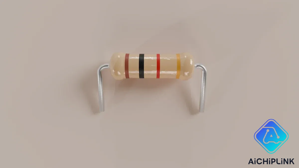
You need to know how to read resistor symbols and their values. The value is usually written next to the symbol. You see numbers and the Ω sign, which means ohms. Sometimes, you see colored bands instead of numbers. The resistor color code uses colors to show the value. You match the colors to a chart to find the resistance. Color codes help you check the value without reading small numbers.
You also see labels like R, RN, or RF. These labels help you pick the right resistor for your circuit. The meaning of the resistor symbol changes with these labels. Always check the value and label before you choose a part. If you use the wrong resistor, your circuit might not work.
Tip: Always check the resistor value and color code before you put a resistor on your board.
Reading Resistor Symbols in Schematics
Reading resistor symbols in big schematics can be hard. You need to know what each symbol means and how it connects to other parts. One problem is telling which part is which. Each symbol should have a name and value to help you find it. You also need to know what the resistor symbol means to see how it affects the circuit.
Another problem is making sure you connect everything the right way. Some parts, like LEDs, need to go in a certain direction. If you connect things wrong, your circuit might not work. When you read resistor symbols, always check the labels, values, and connections. This helps you avoid mistakes and build a working project.
-
Find each resistor symbol and its type.
-
Match the symbol with its value and label.
-
Check connections so your circuit works.
Note: Practice reading resistor symbols and color codes to get better. This makes building and fixing circuits easier.
Resistor Symbols in PCB Design
Schematic to PCB
You start with a circuit schematic. This drawing shows every part and connection. You place each resistor symbol in the schematic editor. You draw lines to connect pins. After you finish, you run an electrical rule check. This step helps you find mistakes. You link each symbol to a footprint. The footprint matches the real part you will use. You export a netlist. The netlist lists all connections in your circuit.
Here is the process you follow:
-
Define your circuit in the schematic editor.
-
Run an electrical rule check to catch errors.
-
Assign footprints to each symbol.
-
Export the netlist.
-
Set up the board shape and design rules.
-
Place components on the board.
-
Route traces between pins.
-
Run a design rule check.
-
Preview the board in 3D.
-
Generate Gerber files for manufacturing.
Tip: Always check that each resistor symbol matches the footprint you need. This step helps you avoid problems later.
EDA Tools
You use EDA tools to design your PCB. These tools help you move from schematic to board layout. Popular EDA tools include KiCad, Eagle, and Altium Designer. You place symbols in the schematic editor. You assign footprints in the library. The software checks your work and helps you fix errors. You can see your board in 3D before you build it.
EDA tools let you:
-
Draw schematics with clear symbols.
-
Assign footprints for each part.
-
Route traces and check for mistakes.
-
Preview your board before sending it to the factory.
Note: Learn the features of your EDA tool. This knowledge helps you design better boards.
Best Practices
You should follow best practices when working with resistor symbols in PCB design. Use clear and standard symbols in your schematic. Assign the correct footprint for each part. Check your work with rule checks. Place resistors where they fit well and make routing easy. Keep traces short and avoid sharp angles. Label each resistor with its value and reference. Review your design before you send it for manufacturing.
Here is a table with best practices:
| Practice | Benefit |
|---|---|
| Use standard symbols | Easier to read and share |
| Assign correct footprint | Fewer mistakes in assembly |
| Run rule checks | Catch errors early |
| Label values clearly | Faster troubleshooting |
| Review before sending | Avoid costly mistakes |
Remember: Careful planning and checking help you build reliable PCBs.
Resistor Packages
Through-Hole vs. Surface-Mount
You see two main types of resistor packages when you build circuits. Through-hole resistors have long metal leads. You push these leads through holes in the PCB. You solder them on the other side. These resistors work well for beginners. You can handle them easily and fix mistakes without much trouble.
Surface-mount resistors look different. They are small and flat. You place them directly on the surface of the PCB. You do not need to drill holes. These resistors save space. You use them in modern electronics like smartphones and laptops. Surface-mount parts need special tools for soldering. You must be careful because they are tiny.
Here is a table to help you compare both types:
| Package Type | How You Use It | Main Benefit | Common Size Example |
|---|---|---|---|
| Through-Hole | Insert in PCB holes | Easy to handle | 1/4W axial |
| Surface-Mount | Place on PCB surface | Saves space | 0603, 0805 |
Tip: Choose through-hole resistors for learning and repairs. Use surface-mount for small, advanced projects.
Matching Symbols to Components
You need to match each resistor symbol in your schematic to the correct physical part. This step helps you avoid mistakes when you order parts or build your board. You use resources like datasheets and part catalogs to check the size, value, and type. You look at the symbol and find the matching package in your resource library.
Follow these steps to match symbols to components:
-
Check the symbol in your schematic.
-
Use a resource like a datasheet to find the right package.
-
Look up the value and size in your resource catalog.
-
Pick the part that fits your board and project needs.
You can use online resources to compare different resistor packages. Many resources show pictures, sizes, and part numbers. These resources help you make smart choices and avoid errors.
Note: Always double-check your resource before you order parts. This step saves time and money.
You make your electronic designs better when you know resistor symbols. These symbols help everyone understand each other. They help you avoid mistakes. You can use a printable resistor symbols chart to find parts fast. Many engineers use a printable resistor symbols chart to fix problems and design circuits. Hackaday has a resistor symbols chart printable for easy use. Keep a printable resistor symbols chart close when you build or fix circuits. If you follow IEC 60617 and IEEE Std 315-1975 standards, your work stays clear. Use a printable resistor symbols chart to check resistor values, color codes, and labels. You make smarter choices and fix problems faster with a printable resistor symbols chart. Try using a printable resistor symbols chart in your next project.
Tip: Download a printable resistor symbols chart before you begin. This easy step helps you work better and quicker.
| Standard | Description |
|---|---|
| IEC 60617 | International standard for graphical symbols for diagrams |
| IEEE Std 315-1975 | Standard for schematic symbols in electronic diagrams |

Written by Jack Elliott from AIChipLink.
AIChipLink, one of the fastest-growing global independent electronic components distributors in the world, offers millions of products from thousands of manufacturers, and many of our in-stock parts is available to ship same day.
We mainly source and distribute integrated circuit (IC) products of brands such as Broadcom, Microchip, Texas Instruments, Infineon, NXP, Analog Devices, Qualcomm, Intel, etc., which are widely used in communication & network, telecom, industrial control, new energy and automotive electronics.
Empowered by AI, Linked to the Future. Get started on AIChipLink.com and submit your RFQ online today!
Frequently Asked Questions
What is the meaning of resistor symbols in circuit diagrams?
You see resistor symbols in diagrams to show where resistors go. Each symbol has a specific meaning. The shape tells you the type. The value next to the symbol shows how much resistance you need. Always check the meaning before you build.
How do you identify resistor values using symbols?
You find the value written next to the resistor symbols. Sometimes, you see color bands on real resistors. Use resources like charts to match colors to numbers. The value tells you how much the resistor slows down current. This helps you pick the right part.
What are the main standards for resistor symbols?
You use standards like IEC, IEEE 315, DIN 40900, and AS 1102. These standards help you read symbols the same way everywhere. DIN symbols and AS symbols look different, but the meaning stays the same. Always check which standard your diagram uses.
Why is resistor symbol identification important in PCB design?
Resistor symbol identification helps you match symbols to real parts. You avoid mistakes when you know the meaning of each symbol. This makes your PCB work as planned. Use resources and check the value for every resistor symbol before you finish your design.
Where can you find resources for learning resistor symbols and values?
You find resources in textbooks, online guides, and datasheets. Many websites offer charts for resistor symbols and value codes. Use these resources to check the meaning of each symbol. This helps you learn faster and avoid errors in your projects.