Table of Contents
- 1.0 What is a Rectifier Circuit and How Does It Work?
- 2.0 A Deep Dive into the Types of Rectifier Circuits
- 3.0 Half-Wave vs. Full-Wave Rectifiers: A Direct Comparison
- 4.0 Practical Rectifiers: Filters, Parameters, and Applications
- 4.3 How to Select the Right Rectifier: Key Parameters
- 4.4 How to Build a Simple Bridge Rectifier Circuit
Every time you plug in your laptop, charge your phone, or power up your TV, an unsung hero of electronics is hard at work. The power from your wall outlet is alternating current (AC), but virtually all of your sensitive electronics require stable, direct current (DC) to function. The fundamental component that bridges this critical gap is the rectifier circuit. Understanding this circuit is not just academic; it's the first step in understanding how nearly every electronic power supply in the world operates. With the global market for power supplies being a multi-billion dollar industry, the importance of efficient AC-to-DC conversion cannot be overstated. This guide will demystify the rectifier, taking you from the basic principles to the different types and their practical applications.
1.0 What is a Rectifier Circuit and How Does It Work?
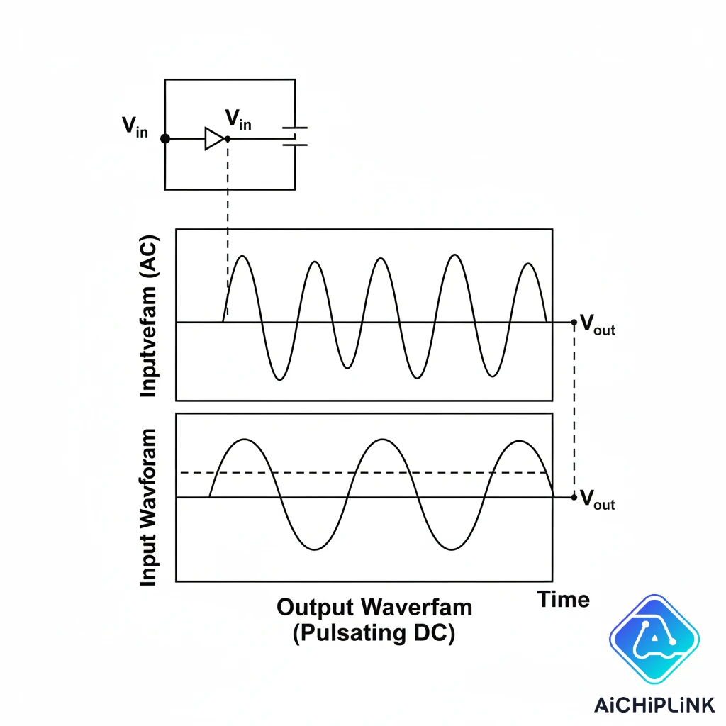
At its heart, a rectifier is an electrical circuit that converts AC into DC. It's the cornerstone of all power supplies that connect to a standard AC source.
1.1 The Core Function: Converting AC to DC
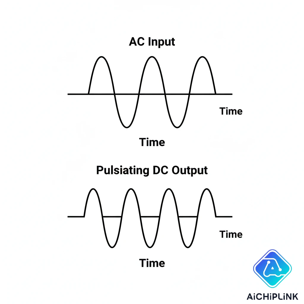
Alternating Current (AC) periodically reverses direction—it flows forward, then backward, in a sine wave pattern. Direct Current (DC) flows in only one direction. The job of a rectifier is to act like a one-way valve for electricity, allowing current to pass through in only the forward direction and blocking it when it tries to flow backward. This process effectively flips or eliminates the backward-flowing half of the AC wave, resulting in a current that flows in pulses but always in the same direction.
1.2 The Key Component: The Rectifier Diode
The magic behind the rectifier circuit is a semiconductor component called a diode. A diode is the electronic equivalent of a one-way street.
- It has two terminals: an anode and a cathode.
- It allows current to flow easily from the anode to the cathode (forward bias).
- It blocks current from flowing from the cathode to the anode (reverse bias). This simple property is what allows diodes to "steer" the flow of AC and achieve rectification. You can explore a wide variety of rectifier diodes designed for this exact purpose.
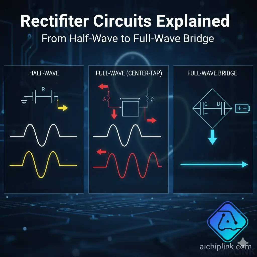
2.0 A Deep Dive into the Types of Rectifier Circuits
Rectifier circuits are categorized by how effectively they utilize the AC input wave. There are two main families: half-wave and full-wave.
2.1 The Half-Wave Rectifier: Simple but Inefficient
The simplest possible rectifier consists of a single diode. This half-wave rectifier allows one half of the AC sine wave (either the positive or negative portion, depending on the diode's orientation) to pass through to the output, while completely blocking the other half.
- Advantage: Extremely simple and cheap, requiring only one diode.
- Disadvantage: Very inefficient, as it throws away half of the available power from the AC source. The resulting DC is very "lumpy" or has a high ripple.
2.2 The Full-Wave Rectifier: Doubling the Efficiency
A full-wave rectifier is a smarter design that utilizes both halves of the AC sine wave. It does this by inverting the negative half of the wave and adding it to the output. This results in a DC output that is much smoother and twice as powerful as a half-wave rectifier. There are two main ways to build one:
- Center-Tapped Transformer: This older design uses two diodes and a special transformer with an extra connection (a "center tap").
- Bridge Rectifier: The more modern and common design.
2.3 The Full-Wave Bridge Rectifier: The Modern Standard
The full-wave bridge rectifier is the most common rectifier circuit in use today. It uses four diodes arranged in a specific bridge configuration. This clever arrangement steers the AC current so that both the positive and negative half-cycles are routed to the output in the same direction, without needing a special center-tapped transformer.
- Advantage: Highly efficient, smooth DC output, and does not require an expensive center-tapped transformer.
- Disadvantage: Uses four diodes instead of one or two, resulting in a slightly higher voltage drop.
"The bridge rectifier was a revolutionary design. Its elegant use of four diodes to achieve full-wave rectification without a complex transformer made efficient and compact power supplies possible for the mass market."
3.0 Half-Wave vs. Full-Wave Rectifiers: A Direct Comparison
The choice between rectifier types comes down to a trade-off between simplicity and performance. For nearly all modern applications, the superior performance of a full-wave bridge rectifier is the clear winner.
3.1 Key Metrics: Efficiency and Ripple Factor
- Efficiency (η): This measures how well the rectifier converts AC input power to DC output power. A higher efficiency means less power is wasted.
- Ripple Factor (γ): This measures how "smooth" the DC output is. A lower ripple factor means the DC is closer to a pure, steady voltage, which is what electronics need.
A full-wave rectifier has double the efficiency and less than half the ripple factor of a half-wave rectifier, making it far superior.
3.2 Technical Comparison Table
| Parameter | Half-Wave Rectifier | Full-Wave (Center-Tap) | Full-Wave (Bridge) |
|---|---|---|---|
| Number of Diodes | 1 | 2 | 4 |
| Max Efficiency | 40.6% | 81.2% | 81.2% |
| Ripple Factor | 1.21 | 0.48 | 0.48 |
| Output Frequency | Same as Input | 2x Input Frequency | 2x Input Frequency |
| Transformer Type | Standard | Center-Tapped | Standard |
4.0 Practical Rectifiers: Filters, Parameters, and Applications
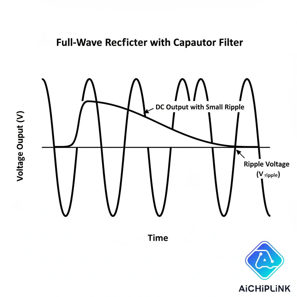
A rectifier on its own produces a pulsating DC. To be useful for electronics, this output must be smoothed into a stable, constant DC voltage.
4.1 The Role of the Filter Circuit (Smoothing Capacitor)
To smooth the pulsating DC, a filter circuit is added to the rectifier's output. The simplest and most common filter is a single large capacitor placed in parallel with the load.
- The capacitor charges up to the peak voltage of the rectifier's output pulses.
- When the pulse voltage drops, the capacitor slowly discharges, supplying current to the load and "filling in the gaps" between the pulses. This action dramatically reduces the ripple and creates a much more stable DC voltage suitable for powering electronic components. More advanced filters may also include inductors, as explained in resources from educational sites like All About Circuits.
4.2 Common Rectifier Circuit Applications
You will find a rectifier circuit in almost any device that plugs into a wall outlet:
- Power Supplies: For computers, TVs, and all consumer electronics.
- Battery Chargers: For phones, laptops, and electric vehicles.
- Variable Frequency Drives (VFDs): Used to control the speed of AC motors.
- Welding: High-power rectifiers are used to provide the stable DC current needed for arc welding.
4.3 How to Select the Right Rectifier: Key Parameters
Moving from theory to a practical build requires selecting the right components. When browsing a datasheet for a rectifier diode or a bridge rectifier, these are the most critical parameters to check:
- Peak Inverse Voltage (PIV): This is the maximum voltage the diode can block in the reverse-biased direction. Your diode's PIV rating (often $V_R$ or $V_{RRM}$) must be higher than the peak voltage of your AC input. For safety, it's common to choose a PIV that is at least 20-25% higher than the peak AC voltage.
- Average Forward Current ($I_F(AV)$): This is the maximum average amount of DC current the diode can safely pass continuously. This rating must be greater than the maximum average current your load will draw.
- Forward Voltage Drop ($V_F$): This is the small voltage "lost" (converted to heat) when current flows through the diode. A lower $V_F$ means the diode is more efficient and will dissipate less heat. In a bridge rectifier, the current always passes through two diodes, so this drop is doubled.
- Reverse Recovery Time ($t_{rr}$): This parameter is crucial for high-frequency applications (like in switching power supplies). For standard 50/60Hz wall power, general-purpose rectifiers are fine. However, for frequencies above a few kilohertz, you must use "fast-recovery" or "ultrafast" diodes to prevent switching losses and heat.
4.4 How to Build a Simple Bridge Rectifier Circuit
You can build a basic full-wave bridge rectifier with four diodes or, more easily, with a single integrated diode bridge component.
- Connect AC Input: Connect the two AC input wires from a transformer to the two terminals marked with a sine wave (~) on the bridge rectifier.
- Connect DC Output: Connect the load (e.g., an LED with a current-limiting resistor) to the DC output terminals. The positive (+) terminal of the rectifier goes to the positive side of the load, and the negative (-) terminal goes to the negative side.
- Add a Filter (Optional): To smooth the output, connect a large electrolytic capacitor across the (+) and (-) terminals, ensuring the capacitor's polarity is correct.
From the simplest single-diode circuit to the highly efficient bridge configuration, the rectifier circuit is an indispensable cornerstone of modern electronics. By converting the ubiquitous AC power from our walls into the stable DC power our devices crave, it performs a task that is both fundamental and essential. As technology advances, especially in high-efficiency power conversion, the principles of rectification remain, continuing to power our world one pulse at a time.
Ready to build your own power supply? Find the perfect rectifier diodes, bridge rectifiers, and other power components for your project at aichiplink.com today!

Written by Jack Elliott from AIChipLink.
AIChipLink, one of the fastest-growing global independent electronic components distributors in the world, offers millions of products from thousands of manufacturers, and many of our in-stock parts is available to ship same day.
We mainly source and distribute integrated circuit (IC) products of brands such as Broadcom, Microchip, Texas Instruments, Infineon, NXP, Analog Devices, Qualcomm, Intel, etc., which are widely used in communication & network, telecom, industrial control, new energy and automotive electronics.
Empowered by AI, Linked to the Future. Get started on AIChipLink.com and submit your RFQ online today!
Frequently Asked Questions
What is the main function of a rectifier circuit?
The main function of a rectifier circuit is to convert alternating current (AC), which periodically reverses direction, into direct current (DC), which flows in only one direction. This is a fundamental process required for powering most electronic devices.
Why is a bridge rectifier better than a half-wave rectifier?
A full-wave bridge rectifier is significantly better than a half-wave rectifier because it is much more efficient. It utilizes both the positive and negative half-cycles of the AC input wave, resulting in a higher average DC output voltage and a lower ripple factor (smoother DC).
What is the purpose of a filter capacitor in a rectifier circuit?
The purpose of a filter capacitor is to smooth out the pulsating DC output from the rectifier. It charges during the voltage peaks and discharges slowly into the load, filling in the gaps between pulses. This drastically reduces ripple and creates a stable DC supply.
What is Peak Inverse Voltage (PIV) for a rectifier diode?
Peak Inverse Voltage is the maximum voltage a diode can withstand in the reverse-biased direction without breaking down. In a rectifier circuit, the diodes must have a PIV rating high enough to handle the peak voltage of the AC input.
Can a rectifier work without a transformer?
Yes, a rectifier can be connected directly to an AC line. These are called transformerless power supplies. However, they are very dangerous because they are not galvanically isolated from the high-voltage AC mains, posing a significant electrocution risk. Transformers are used for both voltage stepping (up or down) and safety isolation.


.png&w=256&q=75)


