Introduction
Calculating total capacitance when combining capacitors is a fundamental skill in electronics, but the rules often confuse beginners because capacitors behave opposite to resistors: capacitors in parallel add directly (like resistors in series), while capacitors in series add reciprocally (like resistors in parallel). This comprehensive guide explains the formulas, provides step-by-step examples, and offers practical tips for easily summing capacitors in any configuration.
Basic Principles
What is Capacitance?
Capacitance (C) measures a capacitor's ability to store electrical charge, measured in Farads (F). Common units:
- 1 Farad (F) = Base unit (very large—rare in practice)
- 1 millifarad (mF) = 10⁻³ F = 0.001 F
- 1 microfarad (µF) = 10⁻⁶ F = 0.000001 F (most common)
- 1 nanofarad (nF) = 10⁻⁹ F = 0.000000001 F
- 1 picofarad (pF) = 10⁻¹² F (high-frequency circuits)
Capacitor Function:
Charge Storage: Q = C × V
Where:
Q = Charge (Coulombs)
C = Capacitance (Farads)
V = Voltage (Volts)
Why Combine Capacitors?
Common Reasons:
- Achieve non-standard values: Need 15µF but only have 10µF and 5µF? Combine them!
- Increase voltage rating: Two 10µF/25V in series → 5µF/50V
- Increase capacitance: Two 10µF in parallel → 20µF
- Filtering applications: Combine different values for broad frequency response
- Component availability: Work with available stock
Capacitors in Series
Formula
For capacitors in series (opposite to resistors):
1/C_total = 1/C₁ + 1/C₂ + 1/C₃ + ... + 1/Cₙ

Or rearranged:
C_total = 1 / (1/C₁ + 1/C₂ + 1/C₃ + ... + 1/Cₙ)
Special Case: Two Capacitors in Series
C_total = (C₁ × C₂) / (C₁ + C₂)

This "product over sum" formula is easier for two capacitors.
Why Series Capacitors Add Reciprocally
Physical Explanation:
- Series connection → charges stored on each capacitor must be equal
- Voltage divides across capacitors: V_total = V₁ + V₂ + V₃
- Since Q = C × V, and Q is constant: V = Q/C
- Total voltage: V_total = Q(1/C₁ + 1/C₂ + ...) = Q/C_total
- Therefore: 1/C_total = 1/C₁ + 1/C₂ + ...
Key Insight: Series capacitors result in lower total capacitance than any individual capacitor.
Series Capacitor Examples
Example 1: Two Equal Capacitors
Given: C₁ = 10µF, C₂ = 10µF (series)

Method 1 (Product over sum):
C_total = (10µF × 10µF) / (10µF + 10µF)
C_total = 100 / 20 = 5µF

Method 2 (Reciprocal):
1/C_total = 1/10µF + 1/10µF = 2/10µF
C_total = 10µF / 2 = 5µF

Result: 5µF (half of either capacitor)
Example 2: Two Different Capacitors
Given: C₁ = 10µF, C₂ = 20µF (series)

Product over sum:
C_total = (10µF × 20µF) / (10µF + 20µF)
C_total = 200 / 30 = 6.67µF

Result: 6.67µF (less than smallest capacitor)
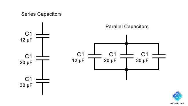
Example 3: Three Capacitors
Given: C₁ = 10µF, C₂ = 20µF, C₃ = 30µF (series)

Reciprocal method:
1/C_total = 1/10 + 1/20 + 1/30
1/C_total = 6/60 + 3/60 + 2/60 = 11/60
C_total = 60/11 = 5.45µF

Result: 5.45µF
Series Connection - Voltage Rating Advantage
Important: Voltage ratings ADD in series!
Example:
- Two 10µF/25V capacitors in series
- Total capacitance: 5µF
- Total voltage rating: 50V

Use case: Need 5µF/50V but only have 10µF/25V caps
→ Series connection solves both capacitance and voltage needs
Capacitors in Parallel
Formula
For capacitors in parallel (same as resistors in series):
C_total = C₁ + C₂ + C₃ + ... + Cₙ

Simply add all capacitance values directly!
Why Parallel Capacitors Add Directly
Physical Explanation:
- Parallel connection → voltage across each capacitor is identical
- Charges add: Q_total = Q₁ + Q₂ + Q₃
- Since Q = C × V: Q_total = C_total × V
- Therefore: C_total × V = C₁ × V + C₂ × V + ...
- Simplify: C_total = C₁ + C₂ + ...
Key Insight: Parallel capacitors result in higher total capacitance than any individual capacitor.
Parallel Capacitor Examples
Example 1: Two Equal Capacitors
Given: C₁ = 10µF, C₂ = 10µF (parallel)

C_total = 10µF + 10µF = 20µF

Result: 20µF (double either capacitor)
Example 2: Three Different Capacitors
Given: C₁ = 10µF, C₂ = 22µF, C₃ = 47µF (parallel)

C_total = 10µF + 22µF + 47µF = 79µF

Result: 79µF
Example 3: Mixed Units (Convert First!)
Given: C₁ = 10µF, C₂ = 4700nF, C₃ = 0.001mF (parallel)

Step 1: Convert to same units (µF)
- C₁ = 10µF
- C₂ = 4700nF = 4.7µF
- C₃ = 0.001mF = 1µF

Step 2: Add
C_total = 10 + 4.7 + 1 = 15.7µF

Result: 15.7µF
Parallel Connection - Current Rating Advantage
Note: Parallel capacitors share current (no advantage)
Unlike voltage in series, current distribution in parallel doesn't increase ratings. However:
- ESR (Equivalent Series Resistance) decreases → lower heating
- Ripple current capacity increases → better for power supply filtering
Mixed Series-Parallel Combinations
Step-by-Step Approach
Rule: Simplify parallel groups first, then series groups
Example: Complex Circuit
Circuit:
[C₁: 10µF] ─┬─ [C₂: 20µF]
            │
            └─ [C₃: 20µF]
            │
─────── [C₄: 5µF] ─────

Solution:
Step 1: C₂ and C₃ are parallel
C₂₃ = 20µF + 20µF = 40µF

Step 2: Redrawn circuit
[C₁: 10µF] ── [C₂₃: 40µF] ── [C₄: 5µF]

Step 3: All are now series
1/C_total = 1/10 + 1/40 + 1/5
1/C_total = 4/40 + 1/40 + 8/40 = 13/40
C_total = 40/13 = 3.08µF

Result: 3.08µF
Quick Reference Table
| Configuration | Formula | Total vs Individual | Voltage Rating |
|---|---|---|---|
| Series | 1/C_total = Σ(1/Cₙ) | Smaller than smallest | Sum of all |
| Parallel | C_total = ΣCₙ | Sum of all | Lowest of all |
Memory Aid:
- Capacitors in SERIES: Like resistors in PARALLEL (reciprocals)
- Capacitors in PARALLEL: Like resistors in SERIES (direct sum)
Practical Applications
Application 1: Power Supply Filtering
Problem: Need 100µF/50V for power supply, only have 47µF capacitors
Solution: Parallel Connection
Two 47µF capacitors in parallel:
C_total = 47µF + 47µF = 94µF ≈ 100µF ✓

Bonus: Lower ESR → better ripple filtering
Application 2: High-Voltage Circuit
Problem: Need 10µF/100V capacitor, only have 22µF/50V
Solution: Series Connection
Two 22µF/50V in series:
C_total = (22 × 22) / (22 + 22) = 11µF
Voltage rating: 50V + 50V = 100V ✓

Result: 11µF/100V (close enough to 10µF need)
Application 3: Achieving Precise Value
Problem: Need exactly 15µF for timer circuit
Solution: Parallel Combination
Available: 10µF and 4.7µF (standard E12 values)
C_total = 10µF + 4.7µF = 14.7µF ≈ 15µF ✓

Alternative: 10µF + 2.2µF + 2.2µF + 0.6µF (if needed)
Common Mistakes to Avoid
Mistake 1: Treating Capacitors Like Resistors
❌ Wrong: Adding capacitors in series directly (10µF + 10µF = 20µF)
✅ Correct: Using reciprocal formula (1/10 + 1/10 = 1/5 → 5µF)
Mistake 2: Ignoring Voltage Ratings
❌ Wrong: Using two 10µF/25V in parallel → assuming 50V rating
✅ Correct: Parallel voltage rating = lowest individual (25V)
Mistake 3: Mixing Units Without Converting
❌ Wrong: 10µF + 4700nF = 4710 (meaningless!)
✅ Correct: Convert first: 10µF + 4.7µF = 14.7µF
Mistake 4: Forgetting Tolerance
Reality: Capacitors have tolerance (±5%, ±10%, ±20%)
Example: 10µF ±20% capacitor
Actual value: 8µF to 12µF

When combining: Account for worst-case tolerance stacking
Conclusion
Calculating capacitors in series and parallel is straightforward once you remember the key rules: series capacitors add reciprocally (1/C_total = Σ1/Cₙ), parallel capacitors add directly (C_total = ΣCₙ)—opposite to resistors. Understanding these formulas enables you to achieve precise capacitance values, increase voltage ratings through series connection, and optimize circuit performance by combining available components effectively.
Key Takeaways:
✅ Series: Reciprocal formula, lower C_total, voltage ratings ADD
✅ Parallel: Direct sum, higher C_total, voltage rating = lowest
✅ Memory Aid: Capacitors are opposite of resistors
✅ Mixed circuits: Simplify parallel first, then series
✅ Always convert to same units before calculating
✅ Voltage ratings: Series adds, parallel takes lowest
✅ Practical use: Achieve non-standard values, increase voltage rating
Building electronics projects? Visit AiChipLink.com for capacitor selection guidance and circuit design consultation.

Written by Jack Elliott from AIChipLink.
AIChipLink, one of the fastest-growing global independent electronic components distributors in the world, offers millions of products from thousands of manufacturers, and many of our in-stock parts is available to ship same day.
We mainly source and distribute integrated circuit (IC) products of brands such as Broadcom, Microchip, Texas Instruments, Infineon, NXP, Analog Devices, Qualcomm, Intel, etc., which are widely used in communication & network, telecom, industrial control, new energy and automotive electronics.
Empowered by AI, Linked to the Future. Get started on AIChipLink.com and submit your RFQ online today!
Frequently Asked Questions
How do you calculate capacitors in series?
Capacitors in series are calculated using the reciprocal formula 1/Ctotal=1/C1+1/C2+..., which results in a total capacitance lower than any individual capacitor. For two capacitors, a shortcut is Ctotal=(C1×C2)/(C1+C2). In series, charge remains constant while voltage divides, and the total voltage rating increases, making this configuration useful for higher-voltage applications.
How do you calculate capacitors in parallel?
Capacitors in parallel are calculated by simply adding their values Ctotal=C1+C2+..., resulting in a higher total capacitance. In this configuration, voltage remains the same across all capacitors while charge adds, and the overall voltage rating is limited by the lowest-rated capacitor.
Why do capacitors in series have lower capacitance?
Capacitors in series have lower capacitance because the effective plate separation increases, reducing the ability to store charge. Since the same charge flows through each capacitor while voltage divides, the total capacitance follows a reciprocal relationship, leading to a smaller equivalent value.
Can I mix different capacitor types in series/parallel?
Yes, different capacitor types can be combined, but careful consideration is required. Factors such as voltage ratings, ESR differences, polarity (for electrolytics), and temperature characteristics can affect performance and reliability, so using similar capacitor types is generally recommended for stable operation.
What happens if I connect capacitors in series backwards?
Connecting polarized capacitors (like electrolytics) backwards can cause serious damage, including overheating, leakage, or even explosion due to reverse voltage stress. Non-polarized capacitors are unaffected by orientation, but polarized ones must always be connected with correct polarity or configured properly for AC use.