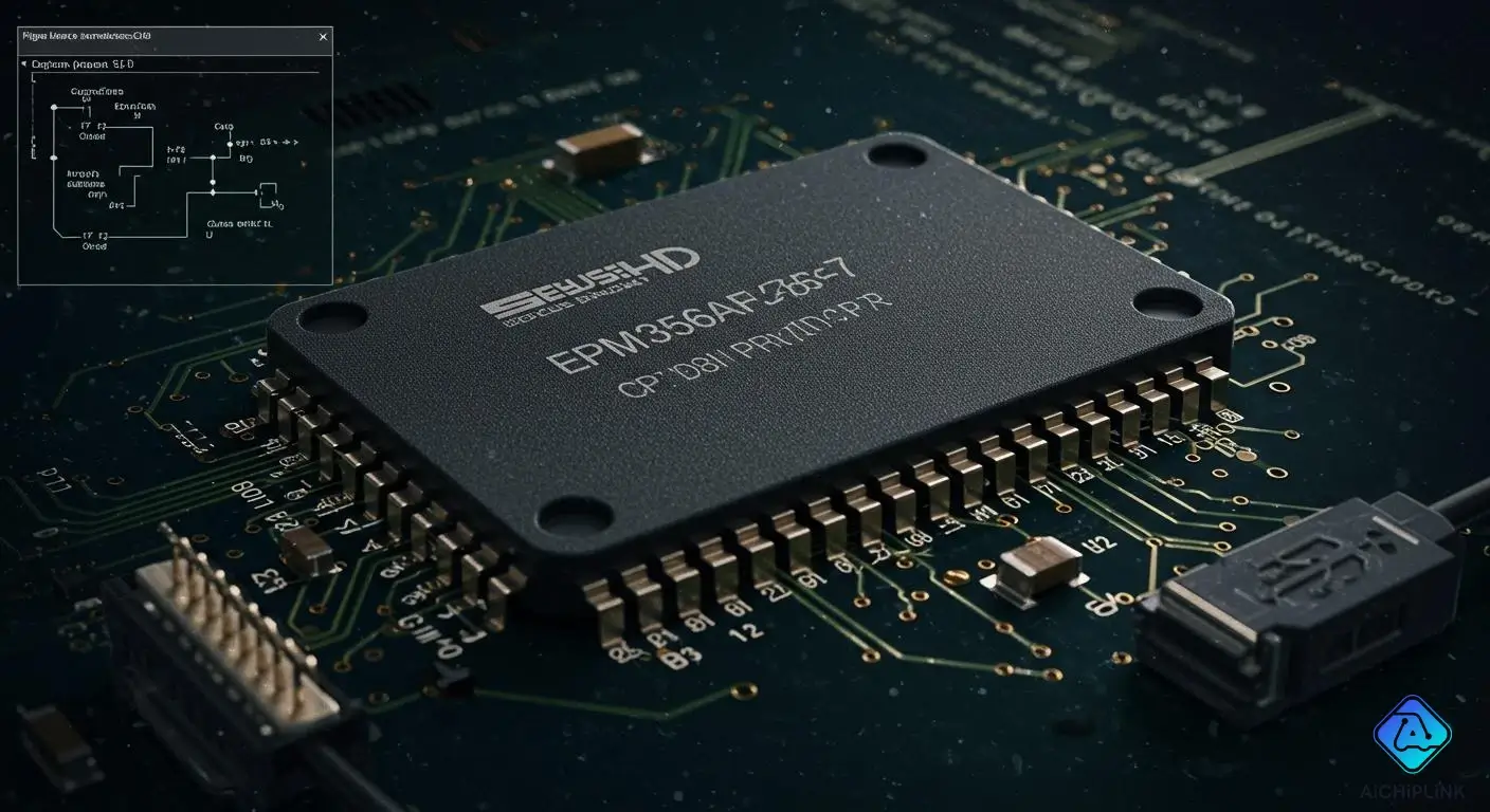
You can use the EPM3256AFC256-7 complex programmable logic device in many electronics projects. This CPLD Overview highlights how this device works as glue logic, assisting with data multiplexing and managing bus interfaces.
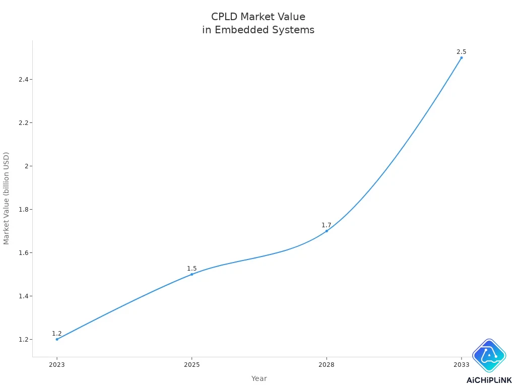
| Year | Market Value (in billion USD) | Unit Shipments (in millions) |
|---|---|---|
| 2023 | 1.2 | 250 |
| 2028 | 1.7 | 350 |
CPLDs are reliable because they maintain their setup even when turned off.
- People use them in automation controllers, telecom equipment, and medical devices.
Key Takeaways
-
The EPM3256AFC256-7 CPLD works well for small projects. It does not cost much and uses little power. It is also very reliable.
-
This CPLD has 256 macrocells. You can make complex digital circuits with it. You do not need to use many chips.
-
You can program the CPLD easily with Intel Quartus and a USB-Blaster. This makes it simple to change your designs when you want.
cpld overview
What is a CPLD
When you learn about digital electronics, you may hear about complex programmable logic devices. A CPLD is a special kind of programmable logic device. It is more advanced than simple ones but not as complex as FPGAs. You can use a CPLD to make your own logic circuits. You do not have to build everything by hand. This helps you finish your projects faster and makes changes easier.
A cpld overview begins with its main parts. Every CPLD has logic blocks, triggers, and channels that connect things. These parts let you decide how the device will work. You can program a CPLD with different types of memory. Some examples are CMOS EPROM, EEPROM, flash memory, or SRAM. This means you can change your design if you need to.
Note: CPLDs remember their setup even when the power is off. This makes them good for many uses.
Macrocell and Architecture
The most important part of a cpld is the macrocell. Each macrocell is like a small piece that does logic work. Logic blocks in a CPLD have several macrocells inside. For example, the EPM3256AFC256-7 CPLD has 256 macrocells. These are grouped into 16 Logic Array Blocks. This setup lets you make complex logic easily.
Here is how the inside of a cpld is set up:
-
Logic Block: Has 4 to 20 macrocells. Each one has a product term array, product term assignment, and registers you can program.
-
Programmable Interconnect Channel: Connects logic blocks, macrocells, and I/O pins together.
-
I/O Block: Connects the inside logic to the input and output pins.
You can set each macrocell for simple or timed logic. This lets you use them for easy or timed jobs. The EPM3256AFC256-7 CPLD gives you exact timing. This is important when you need things to happen at the right time.
A normal macrocell has:
-
Logic Array: Does the main logic work.
-
Product Term Selection Matrix: Lets you pick which logic terms to use.
-
Programmable Registers: Set up for logic or timing jobs.
This setup helps you make digital systems that are strong and flexible.
CPLD vs FPGA
When you read a cpld overview, you might wonder how it is different from an FPGA. Both help you make custom digital circuits. But they are not the same.
CPLDs give you focused flexibility and steady design. FPGAs can do more and are better for big jobs.
Here is a table that shows the main differences:
| Feature | CPLD | FPGA |
|---|---|---|
| Architecture | Non-volatile, simpler architecture | Volatile, complex, and flexible architecture |
| Logic Capacity | Limited, a few thousand gates | Large, from thousands to millions of gates |
| Power Consumption | Lower, suitable for low-power applications | Higher, especially for complex designs |
| Cost | Generally less expensive | Can be more expensive for high-capacity devices |
| Suitability | Ideal for small, cost-sensitive applications | Ideal for complex, high-performance applications |
You will see that a cpld is best for control logic, glue logic, and connecting interfaces. These jobs need fast startup, low power, and steady work. FPGAs are better for fast processing and big, complex systems.
To sum up, a cpld overview shows CPLDs are great for small, low-cost projects. They are good when you need steady and sure performance. FPGAs are better if you need more logic and extra features.
Features
Logic Resources
This cpld gives you lots of logic power. The EPM3256AFC256-7 has 256 macrocells. You can make many digital circuits with it. Each macrocell acts like a small building block. You connect them using logic blocks. This lets you make your own designs. Here is a table that shows the logic capacity:
| Logic Capacity (Macrocells) | 256 |
|---|---|
If you compare this cpld to others, it has more logic and I/O pins. This makes it good for bigger projects.
| Device | Logic Capacity | I/O Pins | Instant-On | Power Use |
|---|---|---|---|---|
| EPM3256AFC256-7 | High | Up to 161 | Yes | Low |
| MAX V | Medium | Fewer | Yes | Very Low |
| XC9572XL | Low | Fewer | Yes | Low |
Performance
You want your circuits to be fast and work on time. This cpld can run at up to 126.6 MHz. It has a short delay of only 7.5 ns.
| Specification | Value |
|---|---|
| Maximum Operating Frequency | 126.6 MHz |
| Propagation Delay - Max | 7.5 ns |
The cpld uses timing that you can count on. You always know how long signals will take. This helps with jobs that need exact timing, like control logic. The way signals move inside and the slew rate settings help keep things steady and quick.
| Feature | Impact on Time-Critical Applications |
|---|---|
| Deterministic Timing Performance | Predictable delays for accurate timing |
| Internal Routing Structure | Predictable delays |
| Slew Rate Configurations | Balances speed and signal integrity |
Power and Reliability
This cpld does not use much power. It keeps your settings even if you turn it off. The cpld starts up right away, so your system is ready fast. You get a device you can trust in many places, like automation or medical tools.
Tip: Pick this cpld if you need something fast, uses little power, and works well for your digital projects.
Pinout
Diagram Overview
When you look at the EPM3256AFC256-7 CPLD, you see a chip with 256 pins. Each pin has a special job. The chip comes in a FineLine BGA package, which means the pins sit underneath the chip in a grid. You do not see the pins on the sides like in older chips.
Here are some key points about the pinout diagram:
-
The diagram shows the layout of all 256 pins.
-
Each pin has a label, such as I/O, VCC, GND, or dedicated function.
-
You find power pins (VCC), ground pins (GND), input/output pins (I/O), and special pins for programming.
-
The diagram helps you connect the chip to your circuit board the right way.
Tip: Always check the official datasheet for the exact pinout diagram before you start wiring your project.
Pin Functions
Each pin on the EPM3256AFC256-7 CPLD serves a purpose. You need to know what each one does to use the chip correctly. Here is a table that explains the main pin types:
| Pin Type | Description | Example Pin Label |
|---|---|---|
| I/O | General input or output | IO1, IO2 |
| VCC | Power supply | VCCINT, VCCIO |
| GND | Ground connection | GND |
| JTAG | Programming and debugging | TDI, TDO, TCK, TMS |
| CLK | Clock input for timing | CLK1, CLK2 |
| NC | No connection | NC |
You use I/O pins to send and receive signals. VCC and GND pins power the chip. JTAG pins let you program and test the CPLD. Clock pins help with timing. Some pins may not connect to anything; these are NC pins.
Note: Always match your circuit to the correct pin functions to avoid errors.
cpld programming
Tools and Software
You need the right tools and software to program the EPM3256AFC256-7 cpld. This programmable logic device works best with industry-standard solutions. Here are the main tools you should use:
-
Intel Quartus
You use Intel Quartus to design, simulate, and compile your digital circuits. This software lets you create logic using programmable logic blocks and then generates the files needed for your cpld. -
USB-Blaster
The USB-Blaster is a JTAG programmer. You connect it to your computer and your cpld board. It lets you send your design directly into the chip.
Tip: Make sure your computer meets the system requirements for Intel Quartus. Always use a genuine USB-Blaster for the best results.
Programming Steps
You can program your cpld by following these steps. This process helps you load your custom logic into the chip and test it in your project.
-
Design and Compile Your Project
Start by creating your circuit design in Intel Quartus. Use the software to draw your logic and set up your inputs and outputs. When you finish, compile the project. This step creates a programming file for your cpld. -
Connect the JTAG Programmer and Hardware
Power your board and connect the USB-Blaster to the JTAG port on your cpld. Double-check the wiring to make sure everything is correct. -
Select the Device and Load the Programming File
Open the programmer tool in Intel Quartus. Detect the cpld on the JTAG chain. Load your programming file and select the right operations. -
Erase, Program, and Verify the Device
Erase any old data on the cpld. Program the new logic into the chip. Use the verify function to check that the programming worked. -
Perform Post-Programming Checks
Test your cpld by sending input signals and checking the outputs. Make sure your design works as expected.
Note: If you have trouble, check your power supply, JTAG connections, and programming file. Try a different USB port or cable if needed.
Best Practices
You want your cpld programming to be safe and reliable. Follow these best practices to avoid problems:
-
Always program your cpld within the recommended temperature and voltage ranges. This keeps your device safe and working well.
-
Double-check all connections before you start programming. Loose wires can cause errors.
-
If you run into issues, check the power supply first. Make sure the JTAG cable is secure. Confirm you are using the correct programming file.
-
Try different USB ports or cables if the programmer does not connect.
-
Restart the Intel Quartus software if you see errors during programming.
Remember: Careful setup and testing help you get the most from your cpld. Good habits make your programmable logic device last longer and work better.
Applications
Use Cases
You can use the EPM3256AFC256-7 cpld in lots of projects. This device is good when you need fast and steady control. Here are some ways people use this cpld:
-
Glue Logic: It helps connect chips or systems that cannot talk to each other.
-
Bus Interface: It moves data between microcontrollers and memory or sensors.
-
Signal Processing: It works with simple digital signals in audio or video devices.
-
Industrial Automation: It controls machines, motors, or sensors in factories.
-
Medical Devices: It helps keep equipment like monitors or pumps working safely.
You can use the cpld instead of many small logic chips. This makes your circuit board easier to build. The logic blocks inside the cpld let you change your design without new hardware.
Tip: Pick a cpld if you want fast startup, low power use, and steady timing in your project.
Integration Tips
When you add the EPM3256AFC256-7 cpld to your system, you want it to work with other parts. The table below shows features that help you use this cpld:
| Feature | Description |
|---|---|
| MultiVolt I/O Support | Works with 2.5 V, 3.3 V, and can take up to 5 V inputs for more choices. |
| Up to 161 User I/O Pins | Lets you connect lots of signals or wide data buses. |
| Slew-Rate Control & Power Optimization | Lets you change output speed and save power on paths that are not important. |
| Internal Programming Voltage Generation | Makes board design easier by making programming voltages inside the chip. |
| Security Bit Protection | Keeps your design safe from copying or reading. |
| TTL/CMOS Compatibility | Works with standard logic levels for easy connections. |
| Deterministic Timing Performance | Gives you steady and predictable timing for important jobs. |
You should match the cpld voltage with other chips. Use slew-rate control to lower noise if your signals do not need to be fast. Use the security bit to keep your logic private. The cpld makes its own programming voltage, so you do not need extra parts.
Note: Always check the datasheet before wiring your cpld. This helps you use the right pins and settings.
The EPM3256AFC256-7 CPLD gives you strong logic, fast speed, and uses little power. You can use this device in many kinds of projects. Here are some ways you might use it:
| Application Type | Description |
|---|---|
| Glue Logic | Joins digital parts, moves data, and helps with decoding. |
| Custom State Machines | Controls timing and steps in a system. |
| Bus Interfaces | Handles moving data and keeps things in sync. |
| Automation Controllers | Runs machines with steady control. |
| Telecom Equipment | Helps with systems that send and get messages. |
| Medical Devices | Adds safe, custom logic to medical tools. |
| Embedded Platforms | Works well in systems that last long and use less power. |
Pick this CPLD if you want logic that is steady, flexible, and simple to program. For more help, look at the datasheet and design guides.

Written by Jack Elliott from AIChipLink.
AIChipLink, one of the fastest-growing global independent electronic components distributors in the world, offers millions of products from thousands of manufacturers, and many of our in-stock parts is available to ship same day.
We mainly source and distribute integrated circuit (IC) products of brands such as Broadcom, Microchip, Texas Instruments, Infineon, NXP, Analog Devices, Qualcomm, Intel, etc., which are widely used in communication & network, telecom, industrial control, new energy and automotive electronics.
Empowered by AI, Linked to the Future. Get started on AIChipLink.com and submit your RFQ online today!
Frequently Asked Questions
How does a CPLD differ from an fpga?
You use a CPLD for easy logic jobs. An fpga does harder tasks. Both can be programmed. Fpga chips have more logic and can do more things.
Can you reprogram the EPM3256AFC256-7 CPLD multiple times?
Yes, you can change this CPLD many times. You use Intel Quartus and a USB-Blaster. This makes your design easy to update.
Is an fpga better than a CPLD for all projects?
No, you pick an fpga for big and hard systems. You pick a CPLD for simple, quick, and low-power jobs. Each chip is good for different needs.
What are field programmable gate arrays used for?
You use field programmable gate arrays for fast data jobs. They help with pictures and special hardware tasks. These chips work well in smart electronics and science.
Can you use an fpga and a CPLD together?
Yes, you can use both chips in one system. The fpga does hard work. The CPLD controls and connects things. This gives you more ways to build your project.