A clamper circuit lets you shift the DC level of an AC signal up or down without changing its shape. You can use a clamper to move the entire waveform higher or lower on a graph. This circuit plays a big role in electronics because it helps you control signals in radios, TVs, and other devices. > When you need to adjust a signal’s position, a clamper gives you that control.
Key Takeaways
-
A clamper circuit moves the DC level of an AC signal. It does not change the signal’s shape. This helps control the signal’s strength better.
-
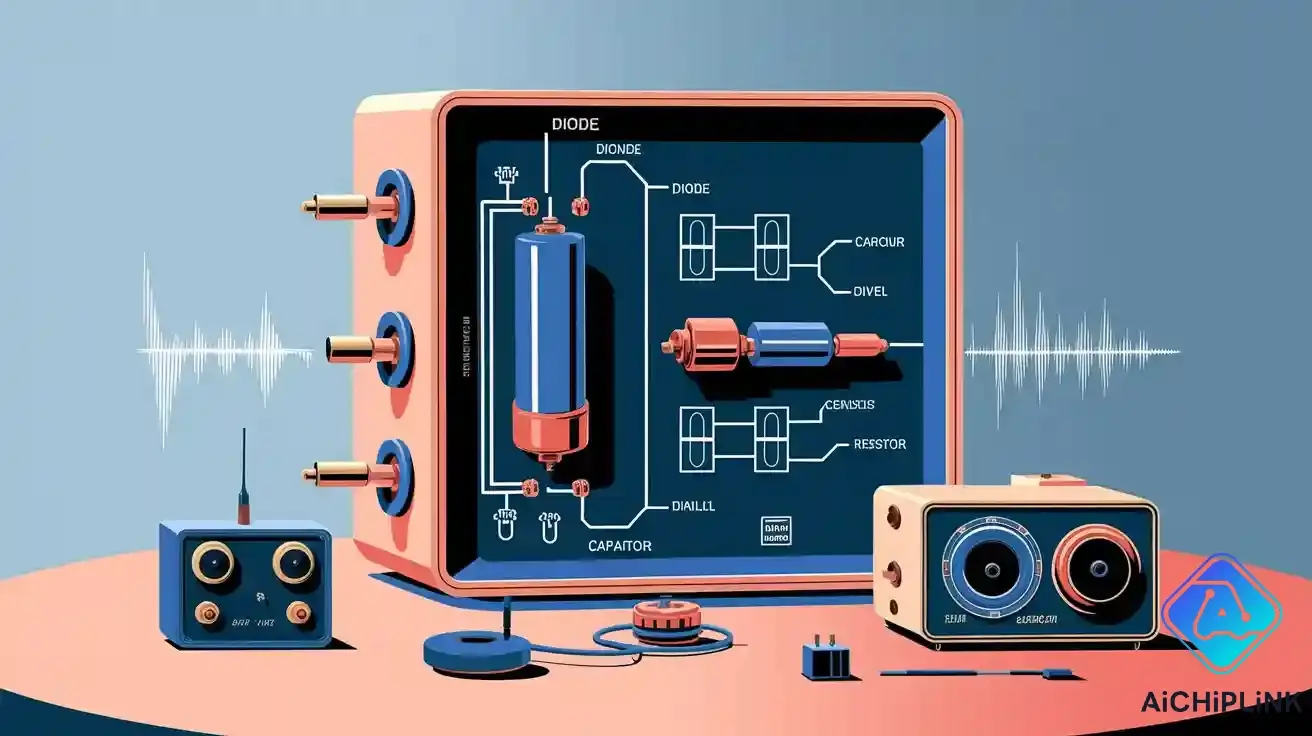
The main parts of a clamper are a diode, capacitor, and resistor. These parts work together to move the signal up or down on a voltage graph.
-
There are three types of clamper circuits. They are positive, negative, and biased. Each type is used for different jobs in electronics.
-
Clampers are very important in things like TVs and radios. They help keep signals clear and stop damage from high voltage.
-
Picking the right capacitor is very important for clamper circuits. The capacitor helps the circuit keep the signal clear and working well.
Clamper Circuit Basics
What is a Clamper Circuit?
A clamper circuit helps you move an AC signal up or down on a voltage graph. It changes the DC level but keeps the signal’s shape the same. In books, you learn that a clamper circuit sets a peak of a waveform to a certain DC level. Most signals go around zero volts, but a clamper lets you pick a new starting point.
The clamper circuit works by adding or taking away a DC part from the input signal. If you add a positive DC level, the signal goes higher. If you add a negative DC level, the signal goes lower. The waveform shape does not change while this happens. You see clamper circuits in devices that need to change voltage levels but keep the signal clear.
Tip: If you take out the diode from a clamper circuit, you only have a coupling capacitor. The diode is needed for the circuit to clamp.
Key Features
You can make a simple clamper circuit with just a few parts. Here is what you need:
| Component | Description |
|---|---|
| Diode | Lets current flow in one direction |
| Capacitor | Holds energy |
| Resistor | Slows down current flow |
| DC Voltage | Optional, gives extra voltage if needed |
Some main things about a clamper circuit are:
-
It moves the DC level of an AC signal up or down.
-
It keeps the original waveform shape the same.
-
It uses a diode, a capacitor, and a resistor.
-
You can add a DC voltage source to set a special level.
You might ask how a clamper circuit is different from a clipper circuit. Here is a table to show the differences:
| Clipper Circuit | Clamper Circuit |
|---|---|
| Cuts off part of an AC signal. | Moves the DC level of the waveform. |
| Also called a voltage limiter or slicer. | Also called a voltage multiplier or DC level shifter. |
| Uses a diode and resistor. | Uses a diode, resistor, and capacitor. |
| Does not need a part to store energy. | Needs a part to store energy, like a capacitor. |
| Changes the waveform shape. | Does not change the waveform shape. |
| Does not change the DC level. | Changes the DC level. |
| Does not change the signal’s strength. | Changes the signal’s strength. |
| Limits the signal’s voltage. | Makes the signal’s voltage bigger. |
| Output voltage is always less than input voltage. | Output voltage is always more than input voltage. |
You use a clipper circuit to cut off parts of a signal. You use a clamper to move the whole signal up or down without changing its shape. Both circuits are important in electronics, but they do different jobs.
How Clamper Circuits Work
Operation Principle
A clamper circuit can move the whole AC signal up or down. It does this on a voltage graph. The shape of the signal does not change. The main job is to add or take away a DC level. You can pick if you want the signal higher or lower.
-
Clamper circuits add or take away a DC level from an AC signal.
-
A positive DC part moves the signal up. A negative DC part moves it down.
-
There are two types: positive clamper (moves up) and negative clamper (moves down).
Both positive and negative clampers do this job. A positive clamper sets the bottom of the wave to a certain DC voltage. When the input is negative, the capacitor charges fast. When the input turns positive, the capacitor helps push the signal higher. In a negative clamper, the capacitor gives a voltage that pulls the signal down. This keeps the output steady.
Note: The clamper circuit does not cut off any part of the signal. It only moves the whole signal up or down.
Role of Capacitor
The capacitor is the most important part of the clamper circuit. It stores and gives back energy at the right time. This keeps the signal shape the same. When the input changes, the capacitor charges or discharges very fast. This lets the circuit move the DC level without changing the signal.
The size of the capacitor matters a lot. If you pick the right one, the circuit works well. It moves the voltage level smoothly and keeps the signal clear. If the capacitor is too small or too slow, the circuit may not work right. This is a bigger problem with high-frequency signals. You might see a weak or messy signal.
| Design Parameter | Influence on Effectiveness | Application Examples |
|---|---|---|
| Choice of Capacitor | Decides how well the circuit moves voltage levels and keeps the signal shape. | Television receivers, Radar |
| Diode Selection | Changes when the circuit lets current flow and how well it works. | Many electronic circuits |
| Time Constant | Needs to charge fast and hold the charge when needed. | Signal processing applications |
Clamper circuits can have trouble with high-frequency signals. The capacitor cannot charge and discharge fast enough. This can make the signal weak or messy. Sometimes, other circuits like clippers work better for these signals.
Tip: Always check your signal’s frequency before using a clamper circuit. For high-frequency signals, you might need something else.
Types of Clamper Circuits
There are three main types of clamper circuits in electronics. Each one moves the signal in its own way. You can pick a positive clamper, a negative clamper, or a biased clamper for your project.
Positive Clamper
A positive clamper circuit moves the whole AC signal up on the voltage graph. You use this when you want the lowest part of your signal to touch zero volts or go higher. The positive clamper adds a DC level to the AC signal. This happens because the input AC signal and the voltage in the capacitor mix during the negative cycle.
-
The positive clamper adds a DC level to the AC signal, so the wave moves up.
-
The output voltage is the input voltage plus the voltage in the capacitor.
-
You see the output as VO = Vm + Vm = 2Vm, so the signal goes higher.
A positive clamper keeps your signal above a certain voltage. This is helpful in TV receivers and audio systems when you do not want negative voltages.
Tip: Use a positive clamper to protect sensitive parts from negative voltages.
Negative Clamper
A negative clamper circuit moves the whole wave down. You use this when you want the highest part of your signal to touch zero volts or go lower. The diode in the negative clamper lets current flow during the positive half cycle. This lets the capacitor charge to a negative voltage.
-
The negative clamper charges the capacitor to a negative voltage during the positive half cycle.
-
When the input signal goes negative, the diode stops current from flowing.
-
The output voltage is the input voltage plus the stored negative voltage, so the wave moves down.
A negative clamper keeps your signal below a certain voltage. This is good for radio receivers and other circuits that need to stop positive voltage spikes.
Biased Clamper
A biased clamper circuit lets you pick any DC level you want. You add a battery or DC source to the circuit. This lets you control where the new peak of your signal will be.
-
Biased clampers use a battery to set a special DC level shift.
-
A positive clamper with positive bias uses the battery to let the diode work during the positive half cycle. The capacitor charges and the output signal moves up.
-
A negative clamper with negative bias uses the battery and input AC voltage to let the diode work. The capacitor charges and the output signal moves down.
A biased clamper is good when you want your signal to start at a special voltage, not just zero. This helps in circuits that need to be very exact and in signal processing.
Here is a table to help you pick the right clamper circuit for your project:
| Type of Clamper | Function | Description |
|---|---|---|
| Positive Clamper | Adds positive offset | Shifts the negative peak to zero volts |
| Negative Clamper | Adds negative offset | Shifts the positive peak to zero volts |
| Biased Clamper | Adds adjustable offset | Sets the new peak to a value other than zero |
Note: Pick the clamper circuit that fits your signal needs. Each type helps you control voltage levels in a different way.
Applications
Signal Processing
Clampers are used in signal processing to keep signals safe and clear. In communication systems, you need to control high voltage peaks. Clampers stop voltage spikes that could hurt your equipment. They also help as power regulators. This means they keep the voltage steady for sensitive devices. If the temperature changes, clampers help keep the signal steady. This is called temperature compensation.
Clampers fix waveforms by making them less noisy and less distorted. This helps your input signal stay clear. Clampers can also work as voltage detectors. They watch the voltage and tell you if it goes past a set point.
-
Stops high voltage peaks
-
Keeps voltage steady for devices
-
Helps signals stay steady when temperature changes
-
Makes waveforms less noisy
-
Watches voltage levels
Tip: Voltage clamping can protect inputs in many new devices.
TV and Radio Receivers
Clampers are important in TV and radio receivers. When video signals are sent, the DC level can get lost. Clampers bring back the DC part. This keeps black and white levels correct. It helps you see a clear picture on the screen. In TVs, clampers fix the blanking level and keep sync signals steady. This makes sure the right voltage goes to the picture tube. You get the right image.
Clampers are also used in radios. They help keep the signal level the same. They stop problems from changes in brightness. Clampers protect parts from voltage spikes. They keep the input signal safe.
-
Bring back DC in video signals
-
Keep black and white levels right
-
Fix blanking and sync signals
-
Protect from voltage spikes
Other Uses
Clampers are found in many other circuits. Oscilloscopes use clampers to move waveforms for better viewing. Communication circuits use clampers to keep signals safe. Clampers protect sensitive parts from sudden voltage changes. They help keep signals steady and stop distortion.
-
Used in oscilloscopes to move waveforms
-
Needed in communication circuits for good signals
-
Protect inputs of sensitive devices
Note: Clampers help keep circuits safe and signals clear in many electronics.
A clamper can move the DC level of an AC signal. It does not change the signal’s shape. The circuit uses a diode, a capacitor, and a resistor. These parts help move the signal up or down. You can pick a positive, negative, or biased clamper for your project.
-
Clampers help set signal levels in lots of devices.
-
The circuit keeps the signal steady and clear.
If you want to learn more about electronic circuits, visit ElecCircuit for easy guides. You can also read "A Person-Centered Guide to Demystifying Technology" for simple activities.

Written by Jack Elliott from AIChipLink.
AIChipLink, one of the fastest-growing global independent electronic components distributors in the world, offers millions of products from thousands of manufacturers, and many of our in-stock parts is available to ship same day.
We mainly source and distribute integrated circuit (IC) products of brands such as Broadcom, Microchip, Texas Instruments, Infineon, NXP, Analog Devices, Qualcomm, Intel, etc., which are widely used in communication & network, telecom, industrial control, new energy and automotive electronics.
Empowered by AI, Linked to the Future. Get started on AIChipLink.com and submit your RFQ online today!
Frequently Asked Questions
What is the main difference between a clamper and a clipper circuit?
A clamper moves the DC level of a signal up or down. It does not change the signal’s shape. A clipper cuts off parts of the signal that are too high or low. Both circuits use diodes, but they do different jobs.
Can you use a clamper circuit for both AC and DC signals?
Clampers work best with AC signals. They shift the DC level of an AC wave. Clampers do not work with pure DC signals. There is no changing part in DC to move.
Why does a clamper circuit need a capacitor?
The capacitor stores energy and gives it back fast. This helps the circuit move the DC level of the signal. The signal shape stays the same. Without a capacitor, the circuit cannot shift the voltage right.
Where do you see clamper circuits in real life?
You find clampers in TVs, radios, and oscilloscopes. They help bring back lost DC levels. Clampers protect sensitive parts and keep signals clear. Many communication devices use clampers to keep signals safe.
How do you choose the right capacitor for a clamper circuit?
Pick a capacitor by looking at the signal’s frequency. Use a bigger capacitor for low-frequency signals. Use a smaller one for high-frequency signals. The right size keeps the signal clear and the circuit working well.


.png&w=256&q=75)


