5 Smart Uses for 0 Ohm Resistors You Need to Know
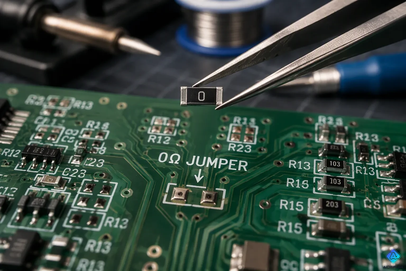
Here's a brain teaser: a resistor with zero resistance might be the most useful part in your toolkit. You'll find these tiny heroes doing five key jobs: jumper or link, placeholder for future components, debugging and signal routing, current sensing, and configuration or mode selection. So why design in a part that does nothing? The answer isn't about resistance at all. A zero-ohm resistor gives you flexibility, saves money, and makes manufacturing easier. Think of it as a strategic placeholder. This zero-ohm resistor lets you keep options open. Every 0 ohm resistor on your pcb buys you room to adapt later.
Key Takeaways
-
Zero-ohm resistors work like jumpers. They take the place of wire links and make PCB assembly easier.
-
They save room for parts you might add later. You can put in new components without changing the board's design.
-
They help find problems in circuits. Take them out to separate parts or move signals easily.
-
They make spots where you can measure. Use them to check current without cutting traces.
-
They pick settings. They fill them in to choose addresses, voltages, or product types.
Functions of Zero-Ohm Resistor: A Quick Overview
Why Designers Rely on Them
An actual zero-ohm resistor is not exactly zero ohms. It has a small built-in resistance, usually in the milliohm range. A common zero-ohm resistor from Rohm or Yageo has a maximum tolerance of 50 milliohms or less. Precision grades make that limit even smaller. The table below lists the common values.
| Source/Standard | Resistance Value |
|---|---|
| Rohm and Yageo spec sheets (max tolerance) | ≤ 50 mΩ |
| F-class precision grade | ≤ 10 mΩ |
| G-class precision grade | ≤ 20 mΩ |
| J-class precision grade | ≤ 50 mΩ |
| Typical actual deviation | ±50 mΩ |
That tiny resistance has a set rated current, so you know exactly how much current the part can handle. Its real value is mechanical and practical. It fits standard pick-and-place packages, and it helps with automated assembly. Later, you can replace it with a real part without changing your pcb layout.
What They Actually Do in a Circuit
Surface-mount zero-ohm resistors are a big manufacturing win over manual jumpers. Pick-and-place machines put them in fast, and automated soldering cuts human error. Surface-mount parts also break less easily than through-hole jumpers because they have no drilled holes that create stress points.
Compared to manual jumpers or wire bridges, a zero-ohm resistor can be placed using standard pick-and-place equipment. This makes manufacturing faster and lowers assembly costs.
You can also combine zero-ohm resistors with magnetic beads, capacitors, and inductors to filter and suppress noise. A ferrite bead plus a capacitor creates a series filter that cleans a noisy power rail. Ferrite beads, however, can create resonance problems. When engineers just need a simple jumper, many swap ferrite beads for zero-ohm resistors. This keeps the pcb flexible for testing without adding unwanted inductance. A zero-ohm resistor also has parasitic inductance of several nanohenries and parasitic capacitance of about 0.1 picofarads. So it stays predictable at high frequencies.
Use 1: 0 Ohm Resistor as a Jumper or Link
PCB Jumper Replacement
A zero-ohm resistor acts as a jumper with very low resistance in a normal resistor package. It links traces without using wire jumpers. You place it with the same pick-and-place machine that handles your other parts. This keeps your pcb layout and routing neat and simple.
Traces can run under the component. That trick cuts down wiring complexity and makes the board look better. Your pcb boards stay flatter and easier to check. A zero-ohm resistor, for example, has tolerance choices of 10 mΩ, 20 mΩ, or 50 mΩ maximum. So you get a part with a known limit you can count on.
Difference Between a Zero-Ohm Resistor and a Wire
The difference between a zero-ohm resistor and a wire shows up in assembly and high-frequency behavior. A zero-ohm resistor and a wire both carry current, but they act in different ways. The table below sums up the key contrasts.
| Attribute | SMD Zero-Ohm Jumper | Traditional Wire Jumper |
|---|---|---|
| Assembly Method | Automated SMT assembly | Manual installation |
| Current Capability | Suitable for high-current PCB designs | Limited by wire size and process |
| Reliability | Consistent production quality | Depends on assembly quality |
| Space Requirement | Compact PCB integration | Requires additional space |
| Inductance | Low parasitic inductance design | Higher parasitic effects |
A zero-ohm resistor also blocks the high-frequency interference that normal jumper wires can bring in. Its flat surface structure and metal film material give more stable parasitic effects. The even current path reduces skin effect. That stops a sharp rise in equivalent resistance as frequency goes up. You also get better impedance matching in high-frequency circuits, like RF module layouts. A jumper resistor still has parasitic inductance of several nH and capacitance of about 0.1 pF. Even so, it beats a hand-soldered wire for repeatability. When you need a jumper, this part gives you a cleaner, more reliable link.
Use 2: Placeholder for Future Components
Designing for Optional Features
Every pcb starts with a plan, but plans change. A zero-ohm resistor saves a standard footprint on the board. It lets you add a real component later without a pcb respin.
Think about a filter stage. One product version needs clean power on a remote chip. Another works fine without extra filtering. You bridge the RC filter footprint with a zero-ohm resistor by default. Assembly installs the link. If noise shows up in testing, you remove the bridge and solder in real filter parts. The footprint stays the same. The same pcb works for both products.
These links also help with optional signal routing. You can choose the signal path at production time. You can pick board variants. Copper traces stay fixed after manufacturing. A populated zero-ohm resistor makes a decision point. One pcb layout then serves many hardware variants.
Development boards use this pattern a lot. They place zero-ohm resistors across unpopulated header footprints. You can swap them with header jumpers later. Power-input sections get bridged on eval boards. The board runs from a single supply during evaluation. Production can split those supplies when needed.
| Modular-design use | How the placeholder works |
|---|---|
| Configuration jumpers | 0-ohm links across header footprints act as config jumpers |
| Single-supply operation | Power sections bridged so one supply powers the board |
| Future filtering | RC filter footprints bridged; later replace with real filters |
| Board variant ID | Populating selected pads identifies the board variant |
Each pattern uses the same trick. A zero-ohm resistor holds a spot. You decide later what goes there.
Swapping in Real Parts Later
Swapping is easy. You remove the link. You install a ferrite bead, a filter, or a real resistor. EMI/EMC compliance might fail during testing. Designers keep this footprint as insurance. Replace the bridge with a filter when noise or radiation goes past the limit. The layout never changes.
Prototyping helps too. Through-hole zero-ohm resistors allow quick changes. You disconnect a sub-system by lifting a link. You reverse TX/RX polarity with a pair of 0-ohm jumpers. Then you set the final routing for production. Component choice defines behavior, not copper traces.
This habit cuts down inventory. This layout supports many product versions. You lower risk. You save rework. This part costs almost nothing. It gives you huge design freedom. Treat it as a placeholder for the unknown. You will reach for it often.
Use 3: Debugging and Signal Routing
Isolating Subcircuits for Testing
A zero-ohm resistor lets you split parts of your circuit in a neat way. You put one between the main power rail and a subsystem block. When you take it out, that subsystem loses all electrical connection. This trick really helps during prototype testing and fault analysis. You can isolate a misbehaving block without touching anything else on the board.
This approach works great in mixed-signal designs. You can use a zero-ohm resistor to make a single-point connection between analog and digital ground planes. That supports single-point grounding for analog and digital grounds. It also keeps the shortest return path for noisy currents. When you need to test one section alone, you just lift the link. The rest of your pcb stays untouched.
Rerouting Without Cutting Traces
Cutting a trace is permanent. A zero-ohm resistor gives you a better choice. You can unsolder it and move the signal path somewhere else. This makes circuit debugging much easier. You avoid scraping copper or repairing damaged boards.
You can also use zero-ohm resistors for EMI control. Swap one for a ferrite bead when radiation problems show up. The footprint stays the same. Signal-path tuning works the same way. Place a zero-ohm resistor in series with a clock line. Later, you can replace it with a real resistor to slow the edge rate. These zero-ohm parts give you debugging and compatibility options you would otherwise lose. Keep a few zero-ohm resistors reserved for debugging on every pcb layout. They cost almost nothing. They also protect your compatibility with future design changes. A zero-ohm jumper is not an ideal short in precision designs. Model it as a real component with parasitic effects. That matters when you check isolation and signal integrity on your pcb.
Use 4: Current Sensing and Measurement Points
Convenient Shunt Location
You need to measure current in a working circuit. A 0 ohm resistor offers a clean break point. Put it in series inside the current path between power domains, sensitive analog stages, or optional subsystems. This opens the circuit without cutting copper. Remove the part and connect your meter. Keep the pads easy to reach on your pcb and give the link a special reference designator. The zero-ohm resistor acts as a current-measurement placeholder. Replace it with a shunt or open it for an ammeter. This setup supports measuring circuit power use without permanent hardware. Monitor the current on the production line, then restore the link afterward.
A zero-ohm resistor's current-carrying capacity depends on its package size, its milliohm-level resistance, and ambient operating temperature. That value is the safe limit. Its capacity to carry current protects your measurement setup. Stay below that limit for normal use. This zero-ohm link can also make a clean current loop for bypassing noisy sections. It keeps the return path short and steady on the pcb.
Measuring Without Permanent Hardware
An ammeter must connect in series. You can't always solder test leads into a production pcb. A simple link fixes that. Remove it, place meter probes across the pads, and read the value. The pcb stays unchanged. You avoid all drilling, cutting, or rewiring. This works best while prototyping and finding faults. Use a zero-ohm resistor to measure battery draw, standby current, or subsystem load.
Some engineers talk about these links as fuses for overcurrent protection. That idea is misleading. A fuse blows at a known fault. The link only breaks the path when you remove it. It is for access, not safety. Do not count on a zero-ohm resistor for precision current sensing. Its milliohm-range tolerance creates error. Instead, pick a specified low-ohmic shunt with Kelvin routing. That gives you accurate, repeatable readings. Even zero ohms of resistance buys design freedom.
Use 5: Configuration and Mode Selection
Hardware Jumpers for Address or Voltage
You can use a zero-ohm resistor as a hardware jumper to choose an address or a voltage rail. Picture a microcontroller board with many sensors on the same bus. Each sensor needs its own I2C address. You put a zero-ohm resistor in one of several pads. That one part sets the address without changing any firmware. Mobile phones and IoT devices use this trick all the time for address selection and rail selection.
Voltage selection works the same way. You place a zero-ohm resistor on one of two power rails. The part connects the load to the rail you want. Its resistance stays below 0.05 ohms, so the voltage drop is very small. The current it can carry depends on the package, material, and thermal conditions. You can choose an 0603, 0805, 1206, or axial part to match your load. This approach keeps your pcb simple and your options open.
One Board, Multiple Product Variants
Adding or leaving out zero-ohm resistors lets the same pcb serve different product options. You build one board design. Then you decide at assembly time which features to turn on. A zero-ohm resistor in one spot turns on a peripheral. Leaving that pad empty turns it off. You avoid a new pcb spin for every product version.
This plan cuts inventory costs and makes your supply chain simpler. You stock one bare pcb and a reel of zero-ohm parts. Your contract manufacturer places or skips them based on the build order. You can also use these parts as removable links during debugging. Open a signal line or reroute it without cutting traces. For RF and analog circuits, a zero-ohm resistor saves a spot for future filtering elements. The same board then adapts to new requirements. You get flexibility, lower risk, and faster time to market.
A zero-ohm resistor links traces, reserves footprints, isolates blocks for debugging, creates measurement points, and selects configurations. That flexibility cuts inventory costs and eases rework. One pcb layout serves many variants. Stock one reel of zero-ohm parts, then populate or skip these zero-ohm links at assembly. Swap in a filter or shunt later. Compatibility becomes a design feature.
Scan your next layout for unknowns. Add a zero-ohm resistor placeholder wherever a component or mode change might appear. This zero-ohm choice costs pennies and saves hours. Rework stays clean; your pcb adapts without a respin. Small, cheap parts carry the biggest design leverage.

Written by Jack Elliott from AIChipLink.
AIChipLink, one of the fastest-growing global independent electronic components distributors in the world, offers millions of products from thousands of manufacturers, and many of our in-stock parts is available to ship same day.
We mainly source and distribute integrated circuit (IC) products of brands such as Broadcom, Microchip, Texas Instruments, Infineon, NXP, Analog Devices, Qualcomm, Intel, etc., which are widely used in communication & network, telecom, industrial control, new energy and automotive electronics.
Empowered by AI, Linked to the Future. Get started on AIChipLink and submit your RFQ online today!
Frequently Asked Questions
Is a zero-ohm resistor really zero ohms?
No, it is not truly zero. A typical part has a small resistance, usually in the milliohm range. Common spec sheets list a maximum tolerance of 50 milliohms or less. Precision grades go even lower. That tiny value still has a defined current rating you can trust.
Can I replace a zero-ohm resistor with a plain wire?
You can, but you lose the benefits. A wire needs manual soldering, which adds time and error. A zero-ohm part fits standard pick-and-place machines. It also gives you stable parasitic effects and a cleaner, more repeatable link on your pcb.
How much current can a zero-ohm resistor handle?
It depends on the package size. Larger packages handle more. Always check the datasheet for the rated current. Stay below that limit for safe, normal operation in your circuit.
Why not just leave the pads empty instead of using a zero-ohm part?
An empty pad breaks the circuit. A zero-ohm link keeps the connection alive. You can also swap it for a real component later without a new pcb spin. That flexibility saves time, cuts inventory, and makes rework much easier.
Do zero-ohm resistors work in high-frequency designs?
Yes, they work well. Their flat surface and metal film give stable parasitic effects. They have low parasitic inductance of several nanohenries and capacitance around 0.1 picofarads. That beats a hand-soldered wire. A zero-ohm jumper stays predictable in RF and analog layouts.