4-Pin and 5-Pin Relay Wiring Made Easy
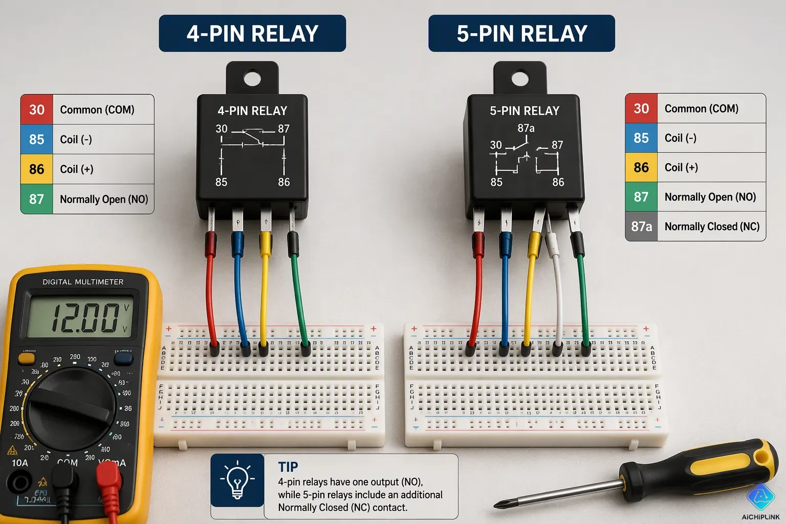
To wire a 4-pin relay, connect Pin 85 to ground and Pin 86 to the switch. Connect Pin 30 to fused battery power, and Pin 87 to the accessory. For a 5-pin relay, wire the same pins. You can also use pin 87a for a normally closed circuit if you want.
This guide shows you what each pin does and how to wire both relay types step by step. It also explains the difference between them and how to fix common problems. You do not need advanced electrical knowledge. According to TechSci Research, the global automotive relay market reached USD 19.02 Billion in 2024. Clear instructions make 4-pin and 5-pin relay wiring simple. You will gain confidence with every relay wiring project.
Key Takeaways
-
Wire a 4-pin relay by connecting pin 85 to ground, pin 86 to your switch, pin 30 to fused power, and pin 87 to your accessory.
-
A 5-pin relay adds pin 87a for a normally closed circuit, giving you a changeover option for dual-state devices.
-
Always fuse the power wire on pin 30 to protect your circuit from short circuits and overloads.
-
Test your relay with a multimeter to confirm proper operation and catch problems early.
-
Use a 4-pin relay for simple on/off tasks and a 5-pin relay when you need a normally closed output.
Relay Basics and 4-Pin & 5-Pin Relay Pin Functions
What a Relay Does
A relay acts as an electrical switch. It uses a small current to control a much larger current. You press a switch, and the relay does the heavy lifting. This small component prevents large currents from flowing through your dashboard controls.
Inside the relay, a coil of wire creates a magnetic field when current flows through it. The magnetic field pulls a metal contact closed or pushes it open. This action lets a low-current switch control a high-current device. For example, a tiny dashboard button can turn on powerful headlights without carrying the full current through the button. The button only activates the coil. The relay handles the rest.
This design protects your switches and reduces the size of wires running through your cab. In automotive relays, the coil typically operates on 12 volts. The load circuit carries the high current to the accessory.
Pin Numbers 30, 85, 86, 87, and 87a
DIN 72552 defines the standard numbering system. People often call these Bosch-style or ISO labels. You will see the same numbers on most 4-pin and 5-pin relay wiring diagrams.
Terminal 30 receives fused battery power for the switched circuit. One coil side handles ground. The other side takes the trigger signal. Energize the coil through pin 85 & pin 86. When you do, pin 30 connects to pin 87. This is the normally open output. The connection delivers power to your accessory. The coil de-energizes when you release the switch. The connection opens.
A 4-pin relay includes pins 30, 85, 86, and 87. It controls a single circuit. A 5-pin relay adds pin 87a. At rest, this output connects to the common contact. When you energize the coil, that connection breaks and the other output takes over. That makes the 5 pin relay a changeover switch between two circuits. You can choose a 4 pin relay for simple on/off jobs. Pick the 5 pin relay when you need a normally closed output that powers a device at rest.
How to Wire a 4-Pin Relay Step by Step
Tools and Materials
Gather your tools before you start. A screwdriver tightens the socket mount. Wire strippers remove insulation without nicking the copper. A crimping tool presses connectors onto wire ends for a secure hold. A multimeter checks voltage and continuity during testing. A heat gun shrinks tubing over each connection. Keep electrical tape and safety glasses nearby too.
For materials, you need a 4-pin automotive relay and a matching socket. Select primary wire sized to your current draw. Buy crimp terminals that fit your wire gauge. An inline fuse holder and fuse protect the circuit. Heat shrink tubing seals every splice. Wire loom and zip ties keep the finished job neat.
Wiring Steps for a 4-Pin Relay
Follow these steps in order to wire a 4-pin relay correctly. This sequence matches standard sample wiring diagrams for a 4 pin normally open relay.
-
Identify each terminal. Pin 30 is the power input. Pin 87 feeds the accessory. Pin 85 is the coil ground. Pin 86 is the trigger signal.
-
Connect pin 30 to the battery positive terminal through an inline fuse. The fuse protects the wiring and the accessory from overcurrent.
-
Connect pin 87 to the positive terminal of your device, such as a horn, fan, or light bar.
-
Connect pin 85 to a clean chassis ground. Avoid rusty or painted surfaces.
-
Connect pin 86 to your control switch or trigger wire. Energizing the coil closes the internal switch.
-
Test the relay. Turn on the switch. You should hear a click, and the accessory should run.
For a ground-switched circuit, reverse the coil connections. Connect the switch to pin 85 and run pin 86 to positive. This negative-trigger variant works with many factory setups.
Always fuse the power wire on pin 30. This single practice prevents short circuits and overloads. A 4 pin relay cannot go in backwards because the pin arrangement is keyed. Incorrect wiring still damages the relay or the load circuit. Double-check every connection before you apply power.
The coil draws very little current. The load circuit carries the full accessory current. This separation is why 4-pin relay wiring protects your switches. Automotive relays handle this job reliably for years when you follow these steps.
How to Wire a 5-Pin Relay Step by Step
Wiring Steps for a 5-Pin Relay
A standard 5-pin relay adds one extra output to the familiar four-pin layout. This extra pin gives you a changeover function. You can control two separate circuits with one small coil signal. Follow these steps to wire a 5-pin relay correctly.
-
Identify each terminal by its standard function. Pin 30 is the common contact. Pin 87 is the normally open contact. Pin 87a is the normally closed contact. Pin 85 is the coil power terminal. Pin 86 is the coil ground terminal.
-
Connect the relay coil. Run pin 85 to a clean chassis ground. Run pin 86 to your control switch or power source.
-
Connect the common load feed to pin 30. This pin receives power from the battery through an inline fuse.
-
Connect the normally open device to pin 87. This circuit turns on when the relay energizes.
-
Connect the normally closed device to pin 87a. This circuit stays on when the relay sits at rest.
-
Test the relay after wiring. Apply voltage to pins 85 and 86. Confirm that pin 30 switches between 87 and 87a as expected.
A 5-pin automotive relay organizes its pins into two functional groups. Pins 85 and 86 form the coil circuit. Pins 30, 87, and 87a form the switching section. This layout works like a single-pole double-throw switch. The coil draws very little current. The load circuit carries the full accessory current. This separation protects your switches and keeps your wiring safe.
Using Pin 87a for a Normally Closed Circuit
The normally closed output is the key feature of a 5 pin relay. This pin keeps a circuit powered when the coil is off. The internal contact rests against pin 87a. When you energize the coil, the contact moves away from 87a and touches pin 87 instead.
| Coil State | Connection of Pin 30 |
|---|---|
| Off (no power to 85/86) | Pin 30 is connected to pin 87a |
| On (coil powered) | Pin 30 is connected to pin 87 |
This behavior makes the 5-pin relay useful for switching between two devices. One example is a headlight system with high and low beams. The low beam stays on at rest through pin 87a. When you trigger the coil, power shifts to the high beam on pin 87.
The ground for the switched circuit is separate from the coil ground on pin 85. The load circuit ground depends on your application. Some devices ground through their own chassis mount. Others need a dedicated return wire. Always check your device requirements before you finish the wiring.
You can also use a 5-pin relay in place of a 4-pin unit. Leave pin 87a unconnected and wire the remaining pins the same way. This trick works well when you upgrade later. The extra terminal sits ready for a future changeover circuit.
4-Pin vs. 5-Pin Relay: Key Differences
4-Pin vs. 5-Pin Automotive Relay Comparison
The biggest difference between a 4 and 5 pin relay is inside the contacts. A 4 pin relay works as a Single Pole Single Throw device. Inside, it has one common input on pin 30, one normally open output on pin 87, and the coil terminals on pins 85 and 86. The internal switch either stays open or connects pin 30 to pin 87. Nothing else happens.
A 5 pin relay works as a Single Pole Double Throw device. It keeps the same four contacts and adds a normally closed output on pin 87a. When the coil sits at rest, pin 30 connects to pin 87a. Energize the coil, and the contact moves to pin 87 while pin 87a disconnects. This changeover action lets one small signal route power between two separate circuits. That single extra terminal defines the difference between 4 or 5 pin relays in every practical job.
When to Use Each Type
A 4 pin normally open relay fits simple on/off tasks. Light bars, horns, and cooling fans all need power only when you flip a switch. A 4-pin automotive relay handles those loads without complaint. A 5-pin automotive relay shines when you need two output states. Headlight beam switching and other dual-state circuits depend on that changeover behavior. Automotive lighting systems also benefit from the safety isolation a 5 pin relay provides. ADAS-related systems now drive higher adoption of the 5-pin design, reported at 65%.
| Automotive Application | Why 5-Pin Relay Is Preferred |
|---|---|
| Automotive lighting | Supports high-frequency switching and safety isolation |
| Headlight beam switching | Enables dual-state control |
| ADAS-related automotive systems | Drives higher 5-pin relay adoption, reported at 65% |
You can swap a 5-pin relay into a 4-pin socket. Leave pin 87a disconnected and insulate the terminal. The remaining contacts behave exactly like a standard 4-pin relay. The reverse never works. A 4-pin relay lacks the normally closed contact, so it cannot perform the changeover function. Keep this rule in mind during 4-pin and 5-pin relay wiring, and you will always pick the right part.
Troubleshooting Common Relay Problems
Relays are dependable, but they can stop working. When your circuit quits, you need a clear way to find the problem. The good news is that most relay issues fit a few known patterns. You can find almost all of them with basic tools and a step-by-step method.
Relay Won't Click or Activate
A silent relay means the coil is not getting power. The coil needs both power and ground to make the magnetic field that moves the switch inside. If either one is missing, nothing happens.
First, check the control side of the circuit. Set your multimeter to DC volts. Put the black probe on ground and the red probe on socket terminal 86. Turn your switch on and off. You should see 12 volts when the switch is on and zero volts when it is off. If power is missing, trace the wiring back to the switch or fuse. Next, check ground at terminal 85. Switch your multimeter to continuity mode. Touch terminal 85 and make sure it connects solidly to ground. Some circuits, like horns, switch on the negative side. In those setups, 12 volts may always be on 86 while 85 only grounds when you press the button.
If both control-side tests pass, test the relay coil directly. Connect terminal 86 to battery positive and terminal 85 to battery negative. Polarity does not matter if the relay has no internal diode. A click means the coil works. Silence means you need a new relay.
You can also measure coil resistance with your multimeter. A healthy 12-volt automotive relay coil should read between 50 and 120 ohms. A reading near 0 ohms means the coil is shorted. An infinite or OL reading means the coil is broken. Both problems mean you need a new relay.
Several common problems cause a relay to fail completely:
-
A faulty coil breaks the path and stops activation.
-
Bad connections at the relay pins block the signal.
-
Control voltage outside the correct range stops proper operation.
-
Overloading the contacts pulls more current than the relay is rated for. This is the most common cause of relay failure. A 30-amp relay powering 45-amp cooling fans overheats the metal contacts until they melt, pit, or weld shut.
-
Moisture, dirt, and corrosion attack a non-sealed relay. Water rusts the copper coil inside and causes an open circuit. Dust coats the contacts and creates high resistance.
-
Voltage spikes and back EMF damage relay contacts. Turning off an inductive load like an AC clutch or wiper motor collapses the magnetic field and sends a high-voltage spike back through the system.
-
Extreme vibration snaps delicate springs inside or loosens the relay pins from their sockets.
-
Wire gauges that are too small or loose crimped terminals create high resistance. This makes intense heat at the relay pins that can melt the plastic base.
A relay tester gives you a fast way to diagnose the problem. Connect the tester to a 12-volt battery. Select 4-pin or 5-pin mode. Put the relay into the correct socket. Press the test button and read the LED indicator. A green light means the relay works properly. A red light means the relay is faulty and needs replacement.
Accessory Stays On or Won't Turn Off
An accessory that never shuts off points to stuck contacts inside the relay. The coil may still click, but the switch inside no longer opens. This problem confuses many people because the relay sounds like it is working.
A relay can click and still be bad. The click only proves the coil is making a magnetic field and the armature is moving. The switching contacts may still be burned, pitted, or carbonized, so they cannot carry electricity to the load.
Use your multimeter to check for welded contacts. Set the meter to continuity mode. With the relay unpowered, probe between pin 30 and pin 87. You should read OL or no continuity. If you read continuity, the normally open contacts are welded shut. For a 5-pin relay, also probe between pin 30 and pin 87a. You should read continuity with very low resistance, usually under 1 ohm. After you energize the coil, that connection should open. If it stays closed, the normally closed contact is stuck.
Here is a quick guide for understanding your multimeter readings:
| Multimeter Reading or Symptom | What It Means |
|---|---|
| Coil shows OL (infinite resistance) | Open coil — relay is dead |
| Coil shows near 0 ohms | Shorted coil windings |
| No click when rated voltage applied | Coil failure, mechanical jam, or wrong voltage |
| Clicks but pin 30 to pin 87 stays OL | Burned, pitted, or misaligned contacts |
| Pin 30 to pin 87 shows continuity before energizing | Contacts welded or stuck closed |
| Pin 30 to pin 87a does not open after energizing | NC contact welded or mechanism stuck |
| Contact resistance unusually high (above 5 ohms) | Oxidized, carbonized, or worn contacts |
A relay swap gives you another simple test. Find an identical known-good relay from a non-critical circuit. Put the suspected bad relay in that non-critical circuit. Put the known-good relay in your problem circuit. Test both. If the problem moves with the relay, the relay is bad. If the problem stays, the fault is in the wiring, fuse, or controlled component.
High contact resistance also causes strange behavior. Oxidized or carbonized contacts may pass enough current to keep a device running weakly. They may also fail to pass enough current to start it at all. Clean contacts show resistance below 1 ohm. Readings above 5 ohms mean worn or damaged contacts that need replacement.
Always check the full circuit after you replace a relay. Make sure your wiring matches the correct pinout. Confirm that pin 30 receives fused battery power. Make sure the ground connections are clean and tight. A new relay in a circuit with a shorted wire will fail again quickly.
Common Applications for 4-Pin and 5-Pin Relay Wiring
Automotive and Lighting Uses
You can find automotive relays in nearly every car on the road. High-output horns, cooling fans, and LED pods often stop working. This happens because factory switches or small wires cannot carry the needed current. A relay lets a low-current dash switch control a circuit that needs more power. This setup keeps high current out of the trigger wiring.
For extra lights, fans, and horns, you usually use pin 30 and pin 87. Pin 87a stays empty. A single 10-inch cooling fan pulls 5–20 amps. A 40A standard Bosch-style relay works well for that. Dual cooling fans need more capacity. A 70A relay is recommended for those tough fan loads. Motors pull more current at startup than resistive loads do. So step up to a higher-rated relay if your circuit is near the limit. Never stack several high-draw accessories onto one undersized relay. Use separate relays and fused circuits instead. For main load circuits, 14-gauge wire works for moderate lighting loads. But 12-gauge or 10-gauge is often better for higher-draw fans, air compressors, and pumps.
| Component | Current Draw | Recommended Relay Rating |
|---|---|---|
| Single 10-inch cooling fan | 5–20 amps | 40A or 70A |
| Dual cooling fans | Higher than single fan | 70A relay recommended |
| High-draw accessories (general) | 15, 20, or 30 amps | Relay handles the load |
Home and DIY Project Uses
A 4-pin relay works for simple on/off jobs around your home or workshop. You can control a 12V pump, a workshop light, or a small compressor with one. A 5-pin relay adds a normally closed output. So it works for changeover tasks like switching between two power sources. A 5-pin automotive relay also fits projects that need a device on at rest.
Safe practices matter for every project. Always disconnect the battery negative terminal before you start wiring. Place a fuse within 18 inches of the power source. Never bypass fuses. Ground the relay base to clean, bare metal instead of painted surfaces. Test the relay with a multimeter. Coil resistance between 85 and 86 should read 70–120Ω for 12V. Check continuity between 30 and 87a when de-energized. Also check between 30 and 87 when you apply 12V to the coil. Avoid swapping 87 and 87a, because that reverses the switching logic. Choose relays with current and thermal ratings that match the actual load. Add about 20% headroom.
Wire a 4-pin relay by connecting pin 85 to ground, pin 86 to your switch, pin 30 to fused power, and pin 87 to the accessory. A 5-pin relay follows the same pattern. You simply gain pin 87a for a normally closed circuit.
Match every pin number with care. Fuse the power wire on pin 30. Test the circuit with a multimeter before you finish the installation. Start with a 4-pin relay for simple on/off jobs. Step up to a 5-pin relay when you need a changeover option. Practice your wiring safely, and your confidence will grow with every project.

Written by Jack Elliott from AIChipLink.
AIChipLink, one of the fastest-growing global independent electronic components distributors in the world, offers millions of products from thousands of manufacturers, and many of our in-stock parts is available to ship same day.
We mainly source and distribute integrated circuit (IC) products of brands such as Broadcom, Microchip, Texas Instruments, Infineon, NXP, Analog Devices, Qualcomm, Intel, etc., which are widely used in communication & network, telecom, industrial control, new energy and automotive electronics.
Empowered by AI, Linked to the Future. Get started on AIChipLink and submit your RFQ online today!
Frequently Asked Questions
Can I use a 5-pin relay instead of a 4-pin relay?
Yes, you can. A 5-pin relay works in a 4-pin socket. Leave pin 87a disconnected and insulate it. The remaining pins behave exactly like a standard 4-pin relay. This swap works well when you plan to upgrade later.
What happens if I wire the relay pins incorrectly?
Incorrect wiring can damage the relay or the accessory. The pin arrangement is keyed, so the relay cannot go in backwards. However, wrong connections on the coil or load pins can cause failures. Always double-check every connection before you apply power.
How do I test a relay with a multimeter?
Set your multimeter to continuity mode. Check for continuity between pin 30 and pin 87 when the coil is unpowered. You should read OL or no continuity. Energize the coil and check again. You should now read continuity. This test confirms the relay works.
Why does my relay click but the accessory does not turn on?
A clicking relay means the coil works. The internal contacts may be burned, pitted, or misaligned. Test for continuity between pin 30 and pin 87 while the coil is energized. An OL reading means the contacts cannot carry current. Replace the relay.
Can I install a relay in any orientation?
Yes, you can mount a standard automotive relay in any position. The internal components work regardless of orientation. However, keep the relay away from extreme heat, moisture, and vibration. These conditions shorten the relay's life.