Introduction
The 5 pin relay is one of the most practical and widely used components in automotive electrical systems, industrial control panels, and DIY electronics projects. It acts as a remote-controlled switch: a small signal current through the relay's coil magnetically closes (or opens) a separate, high-current circuit — letting a tiny control signal from a button, switch, or microcontroller safely operate a powerful load like a headlight, cooling fan, fuel pump, or solenoid valve without routing high current through the dashboard switch.
Despite how common they are, 5 pin relays cause confusion for many people. Which pin is which? Why does one output stay on by default? How do you tell whether a relay has failed? This guide answers all of those questions with clear step-by-step wiring instructions, a complete multimeter testing procedure, practical wiring diagrams for real-world applications, and a troubleshooting guide for the most common relay faults.
Whether you are installing a relay for the first time or diagnosing a fault in an existing system, this is the most complete reference you will find on wiring and testing a 5 pin relay.
1.0 How a 5 Pin Relay Works
A relay is, at its core, an electrically operated switch. Inside the relay housing there are two completely isolated circuits:
The control circuit (coil): A coil of copper wire wound around an iron core. When you apply voltage across the two coil terminals, current flows through the coil and creates a magnetic field. This magnetic field attracts a metal armature (a movable lever) inside the relay.
The switching circuit (contacts): Three electrical contacts — Common (COM), Normally Open (NO), and Normally Closed (NC) — connected to the armature. When the armature moves in response to the magnetic field, it physically changes which contacts are touching, redirecting current in the switching circuit.
This electromagnetic isolation is the relay's key advantage: a small, low-current control signal (from a dashboard switch, ECU output, microcontroller GPIO pin, or sensor) can safely control a large, high-current load (a motor, lamp, or heating element) without the control circuit ever carrying the high current. The relay does all the heavy lifting.
1.1 5 Pin Relay vs. 4 Pin Relay: What Is the Difference?
The difference between a 4 pin and a 5 pin relay is simple: the fifth pin is terminal 87a, which provides the Normally Closed (NC) output.
A 4 pin relay has two coil pins (85 and 86) and two switching pins — the Common (pin 30) and the Normally Open output (pin 87). It is an SPST-NO (Single Pole Single Throw, Normally Open) switch. When the coil is energized, pin 30 connects to pin 87. When de-energized, pin 30 is disconnected from everything. Only one output circuit is possible.
A 5 pin relay adds pin 87a, making it an SPDT (Single Pole Double Throw) switch. Pin 30 always connects to either 87 or 87a — never both, never neither. This means the 5 pin relay can control two separate output circuits: one that is active when the relay is ON and another that is active when the relay is OFF. This "changeover" behavior enables more complex switching logic.
A useful rule: you can always use a 5 pin relay in place of a 4 pin relay — simply leave the 87a pin unused (insulate it). The reverse is not true.
1.2 The Five Pins Explained: 30, 85, 86, 87, and 87a
The pin numbers on standard automotive relays follow DIN 72552, a German automotive industry standard adopted internationally. The five pin numbers and their functions are:
| Pin | Name | Function |
|---|---|---|
| 85 | Coil Ground | One terminal of the electromagnetic coil. Connect to ground (GND / chassis / negative). |
| 86 | Coil Power | Other terminal of the electromagnetic coil. Connect to the control signal (+12V, switch output, ECU signal). |
| 30 | Common (COM) | The main power input to the switching contacts. Usually connected to the battery (+) via an inline fuse. |
| 87 | Normally Open (NO) | Output that connects to pin 30 only when the relay coil is energized. Device connected here is OFF by default. |
| 87a | Normally Closed (NC) | Output that connects to pin 30 when the relay coil is de-energized. Device connected here is ON by default. |
Important notes:
- Pins 85 and 86 are interchangeable for standard relays (the coil has no polarity) — however, for relays with an internal flyback diode, the polarity matters. Always check the diagram printed on the relay body.
- The pin numbers 85, 86, 30, 87, and 87a are molded into the plastic housing next to each terminal. They are not in numerical order around the relay body — their physical positions vary by manufacturer.
- Some relays use alternative numbering (1, 2, 3, 4, 5 instead of 30, 85, 86, 87, 87a). Always verify by reading the diagram on the relay's body or datasheet.
1.3 De-Energized and Energized States
Understanding the two relay states is essential before wiring anything:
De-energized (OFF) state — no voltage applied to the coil:
- The internal spring holds the armature in its rest position
- Pin 30 (Common) is connected to Pin 87a (NC)
- Pin 87 (NO) is open — not connected to anything
- Any device wired to pin 87a will receive power and be ON
- Any device wired to pin 87 will receive no power and be OFF
Energized (ON) state — voltage applied across pins 85 and 86:
- The magnetic field pulls the armature away from its rest position
- Pin 30 (Common) switches to connect to Pin 87 (NO)
- Pin 87a (NC) is now open — disconnected from pin 30
- Any device wired to pin 87 will now receive power and be ON
- Any device wired to pin 87a will lose power and turn OFF
This switching action produces an audible click from the mechanical armature movement — a useful diagnostic indicator that the coil circuit is functioning.
1.4 Coil Voltage, Ampere Rating, and Choosing the Right Relay
Before installing any relay, confirm three specifications match your application:
Coil voltage: The voltage required to energize the relay. Standard automotive relays are 12V DC. Heavy trucks and commercial vehicles use 24V DC relays. Hybrid and electric vehicles may use 48V DC. Installing a 12V relay in a 24V system will instantly burn out the coil. Always verify the coil voltage rating marked on the relay housing.
Contact current rating: The maximum continuous current the switching contacts (pins 30, 87, 87a) can safely carry. Common ratings are 20A, 30A, 40A, and 80A. Select a relay rated for at least 125% of your load's maximum current. A 20A relay running a 30A load will overheat and weld its contacts closed — a dangerous fault.
Contact voltage rating: The maximum voltage the switching contacts can handle. Most automotive relays are rated for 12–14V DC. For switching 240V AC mains or higher DC voltages, use a relay specifically rated for that voltage — a standard automotive relay must never be used for mains voltage.
2.0 How to Wire a 5 Pin Relay: Step-by-Step
2.1 Tools and Materials You Need
Gather these items before starting:
- 5 pin relay (voltage and current rating matched to your application)
- Inline fuse holder + appropriately rated fuse (for the pin 30 power feed)
- Sufficient length of appropriately rated wire (see current capacity below)
- Wire stripper and crimping tool
- Female spade (blade) crimp terminals — 6.3 mm width for standard automotive relays
- Relay socket (optional but recommended — allows the relay to be replaced without cutting wires)
- 1N4007 diode (for flyback protection — see Section 2.4)
- Multimeter (for verification after wiring)
- Electrical tape or heat-shrink tubing
Wire gauge for relay circuits:
| Current | Minimum Wire Gauge |
|---|---|
| Up to 10A | 18 AWG (0.75 mm²) |
| Up to 20A | 16 AWG (1.0 mm²) |
| Up to 30A | 14 AWG (1.5 mm²) |
| Up to 40A | 12 AWG (2.5 mm²) |
| Up to 60A | 10 AWG (4.0 mm²) |
2.2 Wiring the NO Circuit (Device On When Relay Energized)
This is the most common relay wiring configuration — the load is off by default and activates when the relay coil is energized. Use this setup for: auxiliary lights, electric fans, horns, fuel pumps, and any device you want a switch to turn on.
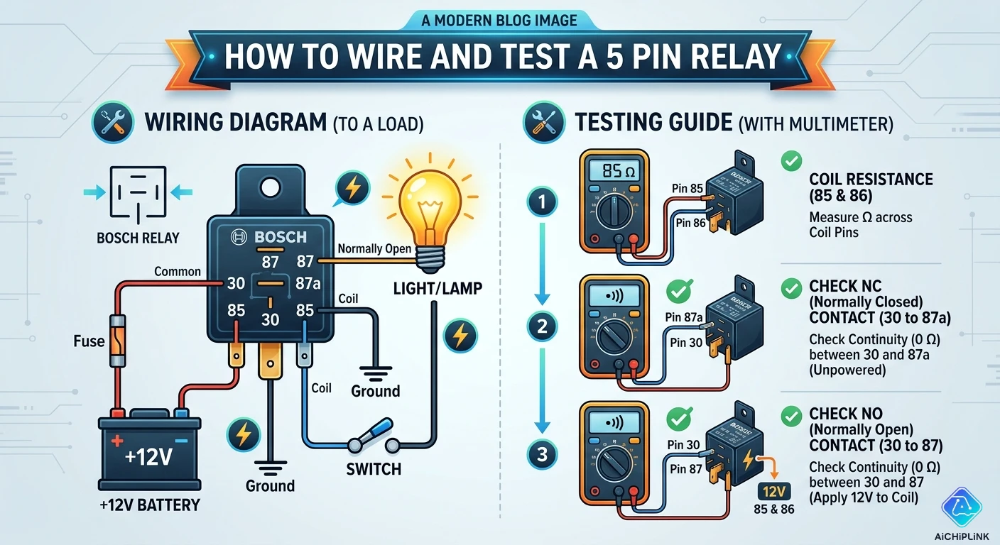
Step 1 — Pin 86 (Coil +): Connect pin 86 to the positive terminal of your control signal — this is the wire from your dashboard switch, ECU output, or other low-current trigger. The switch connects this pin to +12V when activated.
Step 2 — Pin 85 (Coil −): Connect pin 85 to a reliable chassis ground (GND). Find a clean body ground point with no paint between the terminal and bare metal.
Step 3 — Pin 30 (Common, power input): Connect pin 30 to the positive terminal of your vehicle battery via an inline fuse. The fuse value should be rated to protect the wire — typically 125% of the load's maximum current, not more than the relay's contact rating. This fuse is mandatory: pin 30 carries full load current and an unprotected short here could start a fire.
Step 4 — Pin 87 (NO, load output): Connect pin 87 to the positive input terminal of your load (the device you want to control — a light bar, fan motor, horn, etc.).
Step 5 — Load ground: Connect the negative terminal of your load to chassis ground.
Result: When you activate the control switch, +12V reaches pin 86, energizes the coil, and the relay clicks. Pin 30 connects to pin 87, powering the load. When you deactivate the switch, the coil de-energizes, the contacts open, and the load turns off.
Pin 87a: Leave unused. Insulate the terminal with a plastic cap or wrap with electrical tape to prevent accidental short circuits.
2.3 Wiring the NC Circuit (Device On When Relay De-Energized)
This configuration uses pin 87a instead of pin 87. The load is powered by default and turns off when the relay coil is energized. Use this setup for: starter kill switches (disable the starter unless a condition is met), alarm notification systems, or fail-safe circuits where the load must remain active if the control signal is lost.
Steps 1, 2, and 3 are identical to the NO wiring above — coil connections and pin 30 power feed are unchanged.
Step 4 — Pin 87a (NC, load output): Connect pin 87a to the positive input terminal of your load.
Step 5 — Load ground: Connect the load's negative terminal to chassis ground.
Pin 87: Leave unused and insulated.
Result: The load receives power from pin 30 through pin 87a by default. When the coil is energized, pin 30 disconnects from 87a and connects to 87 (which is left open), cutting power to the load.
2.4 Adding a Flyback Diode for Protection
When the relay coil is de-energized, the collapsing magnetic field generates a brief but potentially destructive voltage spike (inductive kickback, also called back-EMF). This spike can reach 50–200V for a fraction of a millisecond — far exceeding the 12V rating of transistors, ECU output pins, and microcontroller GPIO ports that may be driving the relay coil. Over time (or in a single severe event), this spike can damage or destroy the controlling electronics.
The solution is a flyback diode (also called a freewheeling diode or snubber diode) connected across the relay coil:
- Use a standard 1N4007 silicon rectifier diode (inexpensive, widely available, rated 1A / 1000V — more than adequate for this application)
- Connect the diode in reverse bias across pins 85 and 86: the cathode (stripe end) connects to pin 86 (the positive coil terminal), and the anode connects to pin 85 (the ground terminal)
- During normal coil energization: the diode is reverse-biased and has no effect on circuit operation
- During coil de-energization: the voltage spike forward-biases the diode, providing a safe path to dissipate the spike energy harmlessly within the coil loop
When is the flyback diode essential? Always add one when the relay is driven by a transistor, MOSFET, microcontroller output, or automotive ECU — any solid-state device with a limited voltage tolerance. Skip it only when the relay is driven directly by a mechanical switch (the switch contacts can withstand the brief arc without damage).
Note: Some relays include an internal flyback diode already. These relays are polarity-sensitive — connecting pins 85 and 86 backward will short-circuit the diode. Always check the relay body's circuit diagram before wiring a diode-protected relay.
3.0 How to Test a 5 Pin Relay with a Multimeter
Testing a relay with a digital multimeter (DMM) takes less than five minutes and definitively determines whether the relay is functional or faulty. You need the relay removed from its circuit — do not test with the relay still wired to a live system using the resistance/ohms mode.
Set your multimeter to Ohms (Ω) or Continuity mode throughout the tests unless otherwise specified.
3.1 Step 1 — Test the Coil Resistance (Pins 85 and 86)
This test verifies the electromagnetic coil is intact and not open-circuit or short-circuit.
How to test: Place one multimeter probe on pin 85 and the other on pin 86. Read the resistance.
Interpreting the result:
| Reading | Meaning |
|---|---|
| 50–200 Ω (typical 12V relay) | Coil is intact — this is correct |
| "OL" / infinite resistance | Coil wire is broken inside — relay is dead, replace it |
| 0 Ω or near-zero | Coil is short-circuited — relay is dead, replace it |
The exact coil resistance varies by relay model — a 12V / 20A Bosch-style relay typically measures around 70–120 Ω. Check the relay's datasheet or packaging for the specified coil resistance. Any reading within ±20% of the specified value is acceptable.
3.2 Step 2 — Test the NC Contact at Rest (Pins 30 and 87a)
This test verifies the Normally Closed contact is working correctly when the relay is at rest (coil not energized).
How to test: Place one probe on pin 30 and the other on pin 87a. The relay must be unpowered — no voltage on pins 85 or 86.
Interpreting the result:
| Reading | Meaning |
|---|---|
| Near 0 Ω or continuity beep | NC contact is closed — this is correct |
| "OL" / high resistance | NC contact is open or corroded — relay is faulty, replace it |
The NC contact (30 to 87a) must show continuity when the relay is at rest. If it shows open circuit, the NC contact has failed — the armature is stuck in the energized position, or the contact has corroded or burned open.
3.3 Step 3 — Test the NO Contact at Rest (Pins 30 and 87)
This test verifies the Normally Open contact is correctly open when the relay is at rest.
How to test: Keep the relay unpowered. Place one probe on pin 30 and the other on pin 87.
Interpreting the result:
| Reading | Meaning |
|---|---|
| "OL" / high resistance (no continuity) | NO contact is open — this is correct |
| Near 0 Ω or continuity | Contacts are welded shut — relay is dangerous, replace immediately |
If the NO contact shows continuity when the relay is unpowered, the contacts have welded together — a failure mode caused by running too much current through undersized contacts. A welded relay will leave the load powered even when the control circuit is inactive. This is both a performance fault and a potential safety hazard.
3.4 Step 4 — Test Contact Switching Under Power
This is the definitive functional test — verifying that the relay actually switches when the coil is energized.
How to test:
- Apply the correct coil voltage across pins 85 and 86 (connect 12V to pin 86 and GND to pin 85 using a bench power supply or a known-good 12V battery)
- Listen for a clear audible click from the relay — this confirms the armature is moving
- While holding the coil energized, place the multimeter probes on pin 30 and pin 87 — you should now see near 0 Ω / continuity (the NO contact is now closed)
- Simultaneously, pins 30 and 87a should now show "OL" / open circuit (the NC contact has opened)
Interpreting the results:
| Observation | Meaning |
|---|---|
| Click heard + 30-87 continuity + 30-87a open | Relay is fully functional |
| Click heard + 30-87 open (no continuity) | Contact surfaces burned or pitted — relay needs replacement |
| No click + coil reads correct resistance | Coil voltage not reaching relay — check your power source |
| No click + coil reads "OL" | Open coil — relay is dead |
| Click heard + 30-87a still shows continuity | NC contact welded or sticking — relay is faulty |
4.0 Wiring Diagrams, Applications & Troubleshooting
4.1 Automotive Applications: Horn, Fan, Lights, and Starter Kill
The 5 pin relay's SPDT switching capability makes it the default component for dozens of common automotive electrical modifications:
High-current horn circuit (NO wiring): Pin 86 → horn button signal wire; Pin 85 → chassis ground; Pin 30 → battery positive via 20A fuse; Pin 87 → horn(s); horn negative → chassis ground. When the horn button is pressed, the coil energizes and the relay connects battery power directly to the horn — avoiding the need to route high current through the steering column switch.
Radiator cooling fan override (NO wiring): Pin 86 → manual override switch; Pin 85 → chassis ground; Pin 30 → battery positive via 30A fuse; Pin 87 → fan motor positive; fan motor negative → chassis ground. The fan runs only when the override switch is activated.
Headlight relay upgrade (NO wiring): Many stock headlight wiring harnesses route power through undersized switches, causing voltage drop and dim lights. Adding a relay restores full battery voltage to the lights. Pin 86 → original headlight switch output; Pin 85 → chassis ground; Pin 30 → battery positive via 30A fuse; Pin 87 → headlight lamp terminal.
Starter kill / security system (NC wiring): Pin 86 → security system output signal; Pin 85 → chassis ground; Pin 30 → starter motor supply line; Pin 87a → starter motor output (cutting power to starter when relay is unenergized, i.e., alarm is disarmed). When the alarm activates, it energizes the relay coil, disconnecting pin 30 from pin 87a and killing the starter motor circuit.
Dual-output switching (both 87 and 87a used): Pin 30 → power; Pin 87 → Device A (on when relay energized); Pin 87a → Device B (on when relay de-energized). Example: switching between daytime running lights (87a — on by default) and high-beam lights (87 — on when high beam is triggered).
4.2 Common Faults and How to Diagnose Them
Symptom: Relay clicks but load does not turn on The coil circuit is working (click confirms this) but the switching contacts are not delivering power. Check the following in order: (1) Verify the inline fuse on pin 30 is not blown — replace and retest; (2) Confirm pin 87 is connected securely to the load's positive terminal; (3) Verify the load itself has a good chassis ground — a missing or corroded ground is a very common cause of this symptom; (4) Test the relay contacts with a multimeter as per Section 3.4 — burned contacts will click but not conduct.
Symptom: Load is always on and cannot be switched off The load is permanently powered regardless of the control switch position. Cause: the load is wired to pin 87a (NC) instead of pin 87 (NO). The NC terminal is connected to pin 30 by default and only disconnects when the coil is energized — the opposite of what is usually intended for an "on demand" device. Rewire the load from pin 87a to pin 87.
Symptom: Relay gets very hot to the touch This is a dangerous condition indicating overload. Possible causes: (1) The relay's current rating is too low for the load — replace with a higher-rated relay; (2) The wiring to or from the relay is too thin, causing resistance heating — upgrade wire gauge; (3) The load is drawing more current than its rated specification, possibly due to a fault in the load (seized motor, short circuit). Measure load current with a clamp meter before replacing the relay.
Symptom: Relay chatters (rapid clicking) instead of holding steady The coil voltage is insufficient or unstable. Causes: (1) Voltage drop in the coil supply wire — use thicker wire or a shorter run; (2) The coil voltage rating does not match the supply — a 24V relay powered by 12V will chatter; (3) A poor ground connection on pin 85 — clean and re-crimp the ground terminal.
Symptom: No click, load does not operate First, confirm voltage is reaching pin 86 when the control switch is activated — use the multimeter in DC voltage mode (do not use ohms on live circuits). If 12V is present at pin 86 and ground at pin 85 but there is no click, the coil is open (test per Section 3.1). If no voltage is reaching pin 86, the fault is in the control circuit upstream of the relay.
4.3 Selecting the Right 5 Pin Relay for Your Application
When purchasing a 5 pin relay, verify these specifications match your system requirements:
Coil operating voltage: 12V for standard automotive; 24V for heavy commercial vehicles; verify against your vehicle's electrical system. Never guess.
Contact current rating: Rate the relay at least 125% above the load's rated current. For a 20A fuel pump, use a minimum 25A relay — a 30A unit is a better choice. For multiple loads on one relay, add their currents together.
Contact type: Verify the relay has the Form C (SPDT) contact configuration with both NO and NC outputs if you need pin 87a. Some 5-pin housings are actually 4-pin relays in a 5-pin body — check the circuit diagram on the relay housing.
Terminal width: Standard ISO mini relays use 6.3 mm wide blade terminals. Ensure your relay socket or crimp terminals match this width. Micro-relays use narrower 2.8 mm or 3.5 mm terminals.
Mounting orientation: Automotive relays should be mounted with the terminals facing down when possible to prevent moisture accumulation inside the housing.
5.0 Where to Buy Relays
Quality relays are available from automotive parts retailers, electronic component distributors, and specialist suppliers. When purchasing, prioritize established brands (Bosch, Tyco/TE Connectivity, Omron, Panasonic, and Hella are reliable names in relay manufacturing) and verify the relay carries legible, complete specifications on its housing — coil voltage, contact rating, and terminal numbering must be clearly marked.
For reliable sourcing of automotive and electronic relays with verified specifications and competitive pricing, visit aichiplink.com, which stocks a broad range of relay types for automotive, industrial, and electronic applications.
6.0 Conclusion
The 5 pin relay is a straightforward component once its logic is understood: two pins operate the electromagnet coil, and three pins provide an SPDT switching contact that toggles between a Normally Open and a Normally Closed output whenever the coil is energized. Wiring it correctly is a matter of matching pin function to circuit requirement — pin 86 to the control signal, pin 85 to ground, pin 30 to fused battery power, and either pin 87 or pin 87a to the load depending on whether the load needs to be on or off by default.
Testing with a multimeter is equally systematic: check coil resistance (should read 50–200 Ω), verify NC continuity at rest (pins 30–87a: should show continuity), verify NO is open at rest (pins 30–87: should show open), then apply coil voltage and confirm the contacts switch. Any deviation from these expected results points to a specific fault mode — open coil, welded contacts, burned contact surfaces — that tells you exactly what is wrong.
With the right relay specification, a properly rated inline fuse, a flyback diode where needed, and the step-by-step procedure in this guide, you can wire and test any 5 pin relay installation with confidence.
For quality automotive and electronic relays with verified specifications and competitive pricing, explore the range available at aichiplink.com.

Written by Jack Elliott from AIChipLink.
AIChipLink, one of the fastest-growing global independent electronic components distributors in the world, offers millions of products from thousands of manufacturers, and many of our in-stock parts is available to ship same day.
We mainly source and distribute integrated circuit (IC) products of brands such as Broadcom, Microchip, Texas Instruments, Infineon, NXP, Analog Devices, Qualcomm, Intel, etc., which are widely used in communication & network, telecom, industrial control, new energy and automotive electronics.
Empowered by AI, Linked to the Future. Get started on AIChipLink.com and submit your RFQ online today!
Frequently Asked Questions
Does it matter which way around pins 85 and 86 are connected?
In most standard relays, pins 85 and 86 can be connected either way because the coil is non-polarized. However, if the relay includes an internal flyback diode, polarity becomes critical—reversing the connections can short the diode and damage the circuit. As a best practice, connect pin 86 to positive and pin 85 to ground to ensure compatibility with all relay types.
Can I use a 5 pin relay in a 4 pin relay socket?
No, a 5 pin relay will not fit into a 4 pin socket due to the extra terminal (pin 87a). However, in applications that only require normally open (NO) functionality, you can use a 5 pin relay with a 5 pin socket and leave pin 87a unused, or simply choose a 4 pin relay for direct compatibility.
What does it mean when a relay clicks but the load stays off?
A clicking relay indicates the coil is working, but the switching circuit has a problem. Common causes include a blown fuse, faulty wiring, poor ground connection, or worn relay contacts that no longer conduct current under load.
Is it safe to run a relay without an inline fuse on pin 30?
No, running a relay without a fuse on pin 30 is unsafe and can lead to serious damage or fire. Since pin 30 connects directly to the battery, a short circuit can cause excessive current flow, so an appropriately rated fuse should always be installed close to the power source.
Why does my relay work on the bench but fail under load?
A relay may pass bench tests but fail under load due to contact wear or increased resistance. While low-current testing may show continuity, higher load currents can cause voltage drop, overheating, and failure, making replacement with a higher-rated relay the best solution.


