What Is Inductive Reactance? A Complete Guide for Beginners
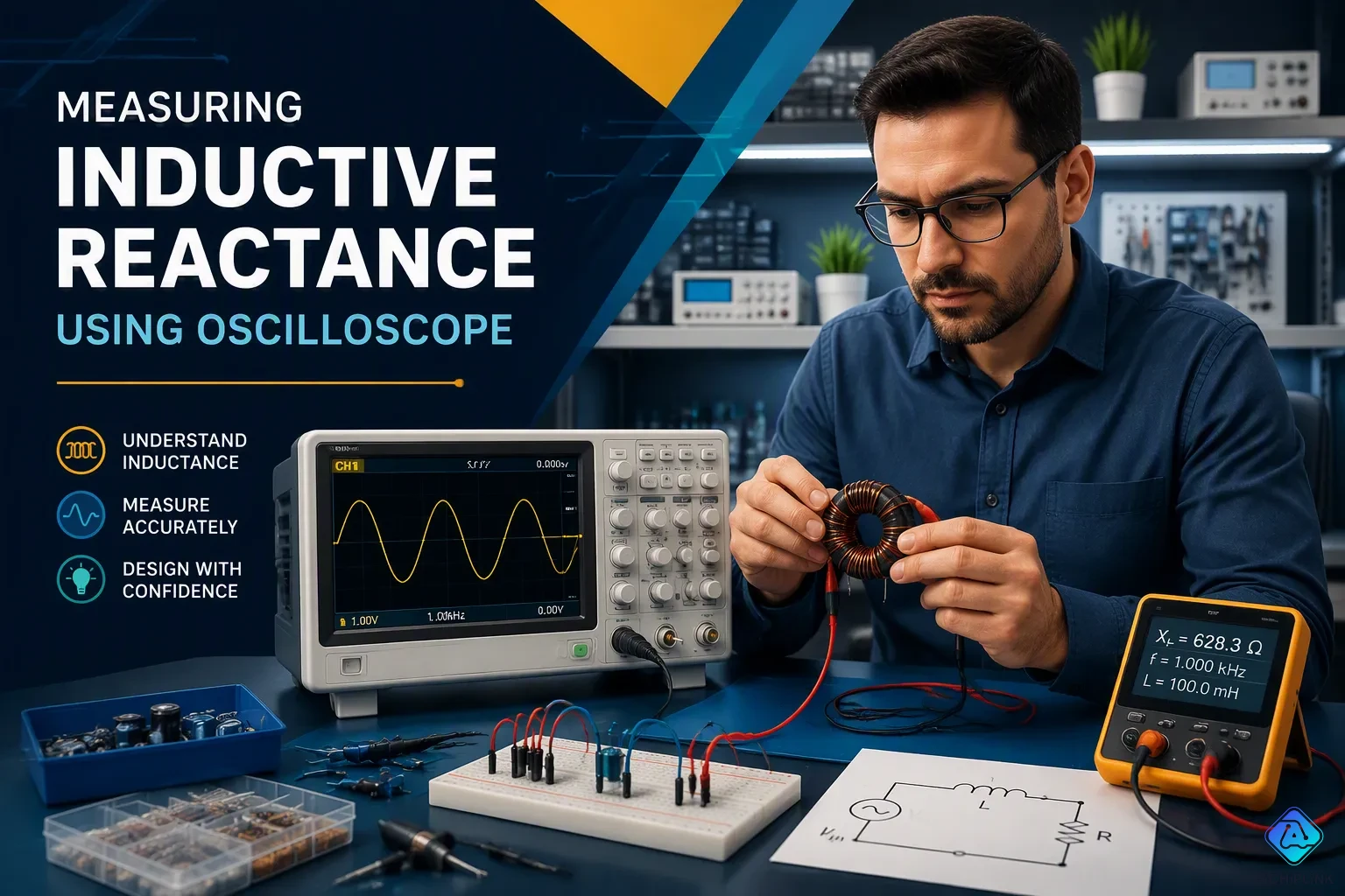
An Introduction to Inductive Reactance: Inductive reactance is how an inductor fights against alternating current. It is measured in ohms, and it gets bigger as the frequency gets higher. This introduction uses a simple analogy: a spring that pushes back against fast pushes. Push slowly, and the spring moves easily. Push quickly, and it pushes back. An inductor acts the same way—it resists changes in current more when the current changes fast. Higher frequency means faster changes, so the opposition grows. When opposition is stronger, the current lags more behind the voltage. But how does this opposition work exactly? Let's break it down.
Key Takeaways
-
Inductive reactance, measured in ohms, is how an inductor resists alternating current.
-
Higher frequency means more opposition, so inductors block high-frequency signals.
-
In an inductor, the voltage reaches its peak 90 degrees before the current does.
-
Use the formula XL = 2πfL to find reactance from frequency and inductance.
-
Inductors work like filters. They let low frequencies go through and block high ones.
Introduction to Inductive Reactance
What Is Inductive Reactance?
This introduction to inductive reactance starts with a definition. An inductor works against changes in alternating current. You measure this opposition in ohms. The name for this opposition is reactance. The effect only shows up in ac circuits. The current must keep changing to make a magnetic field. Direct current makes a steady field. Nothing changes. So no opposition happens. Only ac causes this effect.
The idea of inductive reactance ties frequency straight to opposition. Higher frequency means faster current changes. Faster changes make stronger opposition. This link is key to understanding how inductors act in real circuits.
| Frequency Condition | Opposition Behavior | Circuit Effect |
|---|---|---|
| Frequency increases | Opposition gets stronger | Inductor blocks AC more strongly |
| Frequency approaches infinity | Opposition becomes infinite | Acts like an open circuit |
| Frequency approaches zero or DC | Opposition disappears | Acts like a short circuit |
| General relationship | Opposition is proportional to frequency | Small at low frequencies, large at high frequencies |
This introduction to reactance in ac circuits shows a clear pattern. The table above shows four key conditions. First, as frequency goes up, opposition gets stronger. It blocks AC more strongly at higher frequencies. Second, as frequency gets close to infinity, opposition becomes nearly infinite. The component acts like an open circuit. No current can flow through it. Third, as frequency gets close to zero, opposition nearly goes away. It acts like a short circuit. Current passes with ease. Fourth, opposition is always proportional to frequency. Low frequencies see small opposition. High frequencies see large opposition. This pattern defines how inductors act in every AC circuit.
When frequency goes up, opposition goes up. When frequency goes down, opposition goes down. The component acts as a frequency-controlled part in your circuit. Think of it as a gate that tightens when cars speed up.
This introduction of inductive reactance gives you the foundation. Low frequencies pass through easily. High frequencies face strong blocking. This is why inductors work well in filter circuits. Power supplies use them to smooth out ripple. Audio systems use them to separate high and low frequencies.
The Role of the Inductor
The inductor makes opposition through self-induced back electromotive force. When alternating current flows through an inductor, it makes a magnetic field. The field grows and collapses with each cycle. This changing field makes a voltage that fights the original current. This working of inductor is the source of this opposition.
Here is the key formula that governs this behavior:
Inductive Reactance Equation: XL = 2πfL
Where:
XL = Inductive Reactance in Ohms (Ω)
π = 3.142
f = Frequency in Hertz (Hz)
L = Inductance in Henries (H)
You can use this formula to predict exactly how much opposition a component will provide. For example, take an inductor with L equal to 10 mH and a frequency of 60 Hz. Plug the values into the formula. XL equals 2 times 3.142 times 60 times 0.01. That calculation gives you 3.77 ohms of opposition. Now change the frequency to 100 kHz. The opposition jumps to about 6283 ohms. This big change shows how frequency controls the behavior of the component.
The inductor stores energy in its magnetic field when voltage applies across its terminals. Current through the component cannot change right away. Why? Its own back electromotive force opposes the change. In these circuits, the current alternates all the time. The component keeps fighting the current's rise and fall. This constant opposition is the result of the process.
The back emf is proportional to the rate of current change. This fact explains why frequency matters so much. Higher frequency means faster current changes. Faster changes make larger back emf. Larger back emf gives stronger opposition. The inductor limits current more at higher frequencies. In a purely inductive circuit, current lags voltage by 90 degrees. This phase relationship is a key feature of inductive circuits.
Now you understand this introduction to inductive reactance. A simple component with powerful ac behavior. Use this knowledge for designing filters and power supplies. The component acts as a frequency-dependent resistor. Low frequencies flow through it. High frequencies get blocked entirely. That is the practical value of understanding this property in circuit design.
This introduction to inductive reactance shows you how inductors control AC flow.
How Inductive Reactance Opposes AC
Self-Induced Voltage and Current Lag
Picture an inductor like a traffic jam on a freeway. When cars move slowly, traffic flows with almost no resistance. When cars speed up, the jam gets worse. An inductor acts the same way with alternating current. At low frequencies, current changes slowly and the inductor gives little opposition. At high frequencies, current changes quickly and the opposition gets stronger.
The inductor makes this opposition through self-induced voltage. As current flows through the inductor, it builds a magnetic field. This field collapses and rebuilds with each cycle. The changing field makes a back voltage that fights the source voltage. This back voltage works against the current's rise and fall. The result is a phase lag. The current falls behind the voltage.
An oscilloscope measurement of a 1/2 hp AC motor proves this lag. The voltage trace and current trace showed a time offset of -2.5 ms over a period of 16.7 ms. This made a phase difference of about -54°. The current clearly lagged the voltage in this inductive circuit. The calculated power factor was 0.59.
The Effect of Frequency
The frequency of the ac signal controls how strongly an inductor opposes current. As frequency increases, the induced voltage fights the source more strongly. This leads to a bigger phase lag. The link between frequency and reactance is direct and predictable.
Inductive reactance X_L is proportional to the signal frequency f and the inductance L. X_L = ωL = 2πfL
X_L varies directly as the frequency of the ac source—high frequency causes high inductive reactance.
This means inductive reactance goes up when frequency rises. The reactance increases with a rise in frequency at a steady rate. The graph of reactance versus frequency makes a straight line. This linear link shows that reactance is directly proportional to frequency. You can see this pattern clearly when you plot frequency and reactance on a chart. A low frequency gives small reactance. A high frequency gives large reactance. This rule helps you predict how an inductor will act in any AC circuit.
The Formula for Inductive Reactance
The XL = 2πfL Equation
You can figure out exactly how much an inductor pushes back against alternating current. A simple formula shows this action. Inductive reactance equals two times pi times the frequency times the inductance. This gives you the reactance in ohms.
Here is an example that goes step by step. Use an inductor with 10 millihenries of inductance. Set the frequency to 60 hertz. Put the values into the formula. Multiply 2 times 3.14159 times 60 times 0.01. The answer is 3.77 ohms. That is the reactance at that frequency.
Now use Ohm's law. Suppose you have 10 volts across the inductor. Divide the voltage by the reactance. The current equals 10 divided by 3.77, or about 2.65 amps. This math works only for sinusoidal AC.
The formula comes from how voltage and current relate in an inductor. The voltage across the inductor equals the inductance times how fast the current changes. For a sinusoidal signal, this relationship becomes XL equals 2πfL. You can use this equation without working with derivatives.
Try a second example from a common case. Take an inductor with 0.1 henries of inductance at the same frequency of 60 hertz. The reactance becomes 37.7 ohms. This comparison shows how inductance directly controls the opposition. A larger inductance gives a much higher reactance at the same frequency.
Understanding the Variables
Each variable in the formula has a clear role. The table below shows the units and meanings.
| Variable | Meaning | Unit |
|---|---|---|
| XL | Inductive reactance | ohms (Ω) |
| f | Frequency | hertz (Hz) |
| L | Inductance | henries (H) |
| π | Constant | approximately 3.14159 |
XL stands for inductive reactance. You measure it in ohms. f is the signal frequency in hertz. L is the inductance in henries. The constant π is fixed at about 3.14159.
Inductance values differ a lot across circuits. Small inductors used in high-frequency electronics may have values in microhenries. Power supply inductors often range from millihenries to several henries. Frequency also changes the result a lot. A graph of reactance versus frequency shows a straight line through the origin. As frequency goes up, reactance goes up at the same rate. This linear relationship makes prediction easy.
You can also rearrange the formula to find inductance. If you know the reactance and frequency, divide XL by 2πf. This is the formula to find inductance. It helps you design circuits that need a certain amount of opposition.
Remember that the reactance only shows up in AC circuits. Direct current sees the inductor as a short circuit with zero reactance. In AC, the inductor resists changes in current. The formula gives you the exact opposition for any frequency and inductance value. Practice using the formula with different numbers to build your intuition.
Voltage and Current in an Inductive Circuit
The 90-Degree Phase Shift
In a circuit with only an inductor, voltage and current do not act the same. The current always comes later. We say the current lags behind the voltage by exactly 90 degrees. This quarter-cycle delay shows how an inductor works in an AC system.
Why does this happen? The inductor fights changes in current. When voltage first shows up, the inductor makes a back EMF. This back EMF cancels the applied voltage. Current cannot flow right away. It has to wait for the magnetic field to grow. The voltage hits its peak first. The current peaks a little later. In AC terms, this time is a 90-degree phase difference. We can say that voltage leads the current in this case.
The amount of opposition, or reactance, controls how much current flows. But the phase shift stays the same. It is always 90 degrees for a pure inductor. This is a basic rule of AC theory.
Waveform Visualization
You can see this effect clearly on an oscilloscope. The voltage sine wave starts its cycle. The current sine wave comes after. When the voltage wave is at its highest, the current wave is at zero. This visual offset is the mark of an inductor. Watching the screen, you see the current wave always chasing the voltage wave. This 90-degree lag defines the AC response of the component.
Engineers also use a phasor diagram to show this relationship. A phasor diagram is a simple rotating vector map. It stops time. You draw the voltage as an arrow pointing straight up. You draw the current as an arrow pointing to the right. The angle between them is 90 degrees. In a phasor diagram of an inductor, the voltage arrow always leads the current arrow. This is a key way to show inductive reactance in phasor diagrams.
Studying the phasor diagram helps you understand the phase relationship without looking at sine waves. It is a powerful tool. It makes analyzing AC circuits easier. The phasor diagram shows the current lagging behind the voltage in a clear, still image. The phasor diagram helps you see the effect of frequency changes. As frequency increases, the length of the arrows changes, but the 90-degree angle stays the same. The reactance value changes the length of the arrows but never the angle between them.
Comparing Inductive and Capacitive Reactance
Key Differences
You now know how an inductor fights AC. Let us compare that to a capacitor. A capacitor holds energy in an electric field. Its reactance uses the formula Xc = 1 / (2πfC). See the main difference. Frequency is in the denominator. That changes how it acts compared to an inductor.
The table below shows the main differences between inductive and capacitive reactance.
| Aspect | Inductive Reactance | Capacitive Reactance |
|---|---|---|
| Formula | XL = 2πfL | Xc = 1 / (2πfC) |
| Phase Relationship | Voltage leads current by 90° | Current leads voltage by 90° |
| Frequency Dependence | Greatest at high frequencies | Greatest at low frequencies |
| Behavioral Description | Impedes current at high frequencies; acts like an open circuit at DC | Impedes current at low frequencies; acts like a short circuit at high frequencies |
This comparison of inductive and capacitive reactance shows opposite patterns. An inductor blocks high frequencies. A capacitor blocks low frequencies. A graph of reactance against frequency shows this clearly. The inductor line goes up with frequency. The capacitor line goes down.
Knowing both types matters for making filters and tuning circuits. This blog focuses on inductive reactance, but real circuits often use both parts together.
Practical Applications
Engineers use inductive reactance in many real devices. A choke is an inductor that blocks high-frequency AC. It lets DC or low-frequency current through. Magnetic cores raise impedance at certain frequencies. Audio frequency chokes block audio frequencies and let only DC pass. Radio frequency chokes block RF signals while letting DC and audio through.
Filters use frequency-dependent impedance to pass low-frequency parts and block high-frequency noise. Ferrite core inductors show up in Pi filters, common-mode chokes, and EMI/RFI suppression networks. Color ring inductors work in line filters and boost converters. Laminated steel core inductors handle low-frequency AC chokes and large industrial reactors.
Inductors also store and transfer energy in buck, boost, and flyback power converters. They shape current and cut down ripple. In RF circuits, inductors match source and load impedances for best power transfer. When you connect inductors in series and parallel, you change the total inductance and shift the reactance your circuit shows.
Inductive reactance is how much an inductor pushes back against AC, and it gets bigger as frequency goes up. You find it using XL = 2πfL, where f is frequency in hertz and L is inductance in henries. This pushback makes current lag voltage by 90 degrees. This introduction to inductive reactance matters in real circuits. Chokes use it to block high-frequency noise, and filters depend on it to separate signals. Practice the formula with different frequencies and inductance values. Try 60 Hz and 100 kHz with the same inductor. See how the reactance changes. Now that you get inductive reactance, you're ready to learn how it works with capacitance in AC circuits.

Written by Jack Elliott from AIChipLink.
AIChipLink, one of the fastest-growing global independent electronic components distributors in the world, offers millions of products from thousands of manufacturers, and many of our in-stock parts is available to ship same day.
We mainly source and distribute integrated circuit (IC) products of brands such as Broadcom, Microchip, Texas Instruments, Infineon, NXP, Analog Devices, Qualcomm, Intel, etc., which are widely used in communication & network, telecom, industrial control, new energy and automotive electronics.
Empowered by AI, Linked to the Future. Get started on AIChipLink and submit your RFQ online today!
Frequently Asked Questions
What unit do you use to measure inductive reactance?
You measure inductive reactance in ohms, the same unit used for resistance. The symbol for reactance is XL. Even though both use ohms, reactance and resistance act in different ways in a circuit. Resistance turns energy into heat. Reactance stores and releases energy instead.
Why does an inductor block high frequencies but pass low ones?
An inductor fights changes in current. High frequencies change direction very fast. The inductor's back voltage grows strong and blocks the current. Low frequencies change slowly. The back voltage stays small. Current flows through with little opposition. This is why a choke blocks high-frequency noise.
Does inductive reactance depend on the voltage across the inductor?
No. The reactance value depends only on frequency and inductance. Voltage does not change it. You can raise the voltage across an inductor. The reactance stays the same. The current will rise, but the opposition to AC does not change.
What happens to inductive reactance at DC?
At DC, the frequency is zero. The formula XL = 2πfL gives zero reactance. The inductor acts like a short circuit. Current flows freely once the magnetic field settles. This is why inductors pass DC and block high-frequency AC.
How does inductive reactance differ from capacitive reactance?
An inductor blocks high frequencies and lets low ones through. A capacitor does the opposite. It blocks low frequencies and passes high ones. The phase relationship also flips. Voltage leads current in an inductor. Current leads voltage in a capacitor.