Introduction
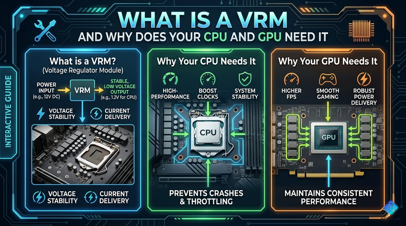
A VRM (Voltage Regulator Module) is a critical power delivery circuit found on every motherboard and graphics card that converts high-voltage power from your PSU (typically 12V) into the precise, stable, low-voltage power required by modern CPUs and GPUs (often 0.6V-1.5V). Without a properly functioning VRM, your processor cannot operate—it would either receive too much voltage (causing damage) or insufficient power (causing crashes and instability). This comprehensive guide explains what VRMs are, how they work, why they're essential for CPU and GPU operation, how VRM quality affects system performance and overclocking potential, and what to look for when choosing motherboards and graphics cards.
VRM Definition & Function
What is a VRM?
VRM (Voltage Regulator Module) = Specialized power supply circuit that:
- Converts voltage from PSU (12V) to CPU/GPU requirements (typically 0.6V-1.5V)
- Regulates voltage precisely to maintain stability under varying loads
- Delivers high current (100A+ for modern CPUs/GPUs)
- Responds rapidly to power demand changes (microsecond response time)
Simple Analogy: Think of a VRM as a smart water pressure regulator in your home—it takes high-pressure water from the main supply and converts it to safe, consistent pressure for your faucets, automatically adjusting when you turn taps on/off.
VRM Location
On Motherboards:
[PSU 12V] → [24-pin ATX connector] → [Motherboard VRM] → [CPU socket]

Physical location: Near CPU socket (clustered components with heatsinks)
Typical appearance: Multiple inductors (coils), MOSFETs, capacitors
On Graphics Cards:
[PSU 12V] → [PCIe power connector] → [GPU VRM] → [GPU chip]

Physical location: Around GPU die perimeter
Often covered by: VRM heatsinks or backplate
Basic VRM Function
Primary Job: Voltage Conversion
Example:
Input: 12V from PSU
Output: 1.2V for CPU core
Current: 150A under full load

Power delivery:
12V × 12.5A (input) ≈ 1.2V × 150A (output) = 180W
(accounting for ~85-95% efficiency)
Key Features:
- Dynamic voltage adjustment: Changes voltage based on CPU P-states (power states)
- Load-line calibration: Compensates for voltage droop under load
- Current sensing: Monitors power delivery to prevent overcurrent
- Temperature protection: Thermal shutdown if VRM overheats
How VRM Works
VRM Components
1. MOSFETs (Metal-Oxide-Semiconductor Field-Effect Transistors)
Function: Electronic switches that rapidly turn on/off to chop incoming 12V into pulses
Types:
- High-side MOSFET: Connects to 12V input
- Low-side MOSFET: Connects to ground
- Switching frequency: 300 kHz - 1 MHz typical
2. Inductors (Chokes)
Function: Smooth pulsed voltage from MOSFETs into steady DC voltage
Appearance: Toroidal or cylindrical coils (often largest VRM components)
Rating: Measured in microhenries (µH), typically 0.5-1.0 µH
3. Capacitors
Function: Filter voltage ripple, store energy for rapid load changes
Types:
- Input capacitors: Large electrolytics near 12V input
- Output capacitors: Polymer/ceramic near CPU socket (low ESR critical)
4. PWM Controller (Pulse Width Modulation)
Function: Brain of VRM—monitors output voltage, controls MOSFET switching
Key tasks:
- Compares actual vs target voltage
- Adjusts MOSFET duty cycle to maintain regulation
- Coordinates multi-phase operation
VRM Operation Cycle
Step-by-Step Process:
Step 1: PWM Controller Reads Target Voltage
CPU requests: 1.2V via VID (Voltage Identification)
VRM controller receives: Target = 1.2V
Step 2: MOSFETs Switch Rapidly
High-side ON (12V flows) → Low-side OFF
Duty cycle: ~10% (1.2V / 12V)
Frequency: 500 kHz (switching every 2 microseconds)
Step 3: Inductor Smooths Voltage
Pulsed 12V (10% duty) → Inductor → ~1.2V average
Inductor resists current changes, creating smooth output
Step 4: Capacitors Filter Ripple
Output voltage: 1.2V ± 10mV ripple
Capacitors absorb high-frequency noise
Step 5: Feedback Loop Adjusts
Actual voltage: 1.18V (below target)
PWM controller: Increase duty cycle to 10.5%
New output: 1.2V (target achieved)
Multi-Phase VRM
Why Multiple Phases?
Single-Phase Limitations:
- High current stress on components
- Large voltage ripple
- Poor transient response
- Component overheating
Multi-Phase Advantages:
Example: 8-Phase VRM
Total current: 160A
Per-phase current: 160A / 8 = 20A (manageable)

Ripple reduction:
1-phase: ±100mV ripple
8-phase: ±12mV ripple (8× better)

Thermal distribution:
1-phase: Single inductor handles 160A (very hot)
8-phase: Each inductor handles 20A (cool operation)
Phase Interleaving:
Phase 1: ON─OFF────ON─OFF────
Phase 2: ──ON─OFF────ON─OFF──
Phase 3: ────ON─OFF────ON─OFF
...

Result: Effective switching frequency × number of phases
8 phases @ 500 kHz = 4 MHz effective frequency (smoother output)
Why CPU and GPU Need VRM
Reason 1: Voltage Requirements
Modern Processors Require Low Voltage:
| Component | Voltage Range | Reason |
|---|---|---|
| CPU Core | 0.6V - 1.5V | Smaller transistors (7nm, 5nm) need lower voltage |
| GPU Core | 0.8V - 1.2V | Similar transistor scaling |
| PSU Output | 12V, 5V, 3.3V | Standard ATX specification |
Why Not Use 12V Directly?
- Modern CPUs/GPUs would instantly burn out at 12V
- Transistors designed for 1V operation would suffer gate oxide breakdown
Why Not Lower PSU Voltage?
- Power transmission efficiency: P = V × I
- 12V @ 10A = 120W (manageable cable size)
- 1.2V @ 100A = 120W (requires massive cables, high resistance losses)
Reason 2: Precise Voltage Regulation
CPUs/GPUs Need Tight Voltage Tolerance:
Example:
CPU specification: 1.20V ± 50mV (1.15V - 1.25V acceptable)

Too low (<1.15V): System crashes, computation errors
Too high (>1.25V): Reduced lifespan, potential damage
Optimal (1.20V ± 10mV): Stable operation, maximum performance
VRM Provides:
- Voltage accuracy: ±1-2% typical (±12-24mV at 1.2V)
- Fast response: Adjusts voltage in microseconds when load changes
- Load regulation: Maintains voltage despite current swings (0A → 150A)
Reason 3: Dynamic Power Management
CPUs/GPUs Constantly Change Power Draw:
Example Scenario (Gaming):
Time 0s: Desktop idle → 20W → VRM delivers 1.0V @ 20A
Time 1s: Game launches → 150W → VRM ramps to 1.3V @ 115A
Time 2s: Loading screen → 50W → VRM reduces to 1.1V @ 45A
Time 3s: Intense combat → 200W → VRM delivers 1.35V @ 148A
VRM Must:
- Respond to load changes in <10 microseconds
- Prevent voltage droop (output sagging under heavy load)
- Avoid voltage overshoot when load decreases
Without VRM:
- Voltage would fluctuate wildly (0.5V - 3V swings)
- CPU/GPU would crash or suffer permanent damage
Reason 4: High Current Delivery
Modern CPUs/GPUs Draw Massive Current:
| Processor | Power Draw | Voltage | Current Required |
|---|---|---|---|
| Intel Core i9-14900K | 253W (turbo) | ~1.3V | ~195A |
| AMD Ryzen 9 7950X | 230W (boost) | ~1.25V | ~184A |
| NVIDIA RTX 4090 | 450W | ~1.0V | ~450A |
VRM Challenge:
- Deliver 100-450A continuously
- Handle transients (instant power spikes)
- Minimize voltage droop (<50mV at full load)
Solution: Multi-Phase VRM
- 16-phase CPU VRM: 195A / 16 = ~12A per phase (manageable)
- 24-phase GPU VRM: 450A / 24 = ~19A per phase
VRM Quality & Performance Impact
VRM Phase Count
Common Configurations:
| Phase Count | Target Use | Example |
|---|---|---|
| 4-6 phase | Budget CPUs (65W TDP) | Office PCs, entry gaming |
| 8-10 phase | Mainstream (125W TDP) | Mid-range gaming, productivity |
| 12-16 phase | High-end (150-200W) | Enthusiast gaming, overclocking |
| 18+ phase | Extreme (250W+) | Flagship CPUs, LN2 overclocking |
Note: Marketing often lists "doubled" phases (e.g., "16-phase" may be 8 real phases with doublers)
VRM Component Quality
Budget VRM (Low Quality):
- MOSFETs: High RDS(on) (resistance) → More heat, lower efficiency
- Inductors: Lower current rating → Saturation at high load
- Capacitors: High ESR → More ripple, shorter lifespan
- PWM Controller: Basic, no advanced features
Premium VRM (High Quality):
- MOSFETs: Low RDS(on) DrMOS → Cooler, 90%+ efficiency
- Inductors: High saturation current → Stable at peak load
- Capacitors: Solid polymer, low ESR → Minimal ripple, 10+ year lifespan
- PWM Controller: Advanced (e.g., IR35201) → Better regulation, OCP/OTP
Performance Impact
Scenario: CPU Overclocking
Poor VRM (4-phase budget):
Stock (3.8 GHz): Stable, VRM warm (70°C)
Overclocked (4.5 GHz):
- VRM temperature: 110°C (thermal throttling)
- Voltage droop: 1.35V → 1.28V under load (unstable)
- Result: Crashes, cannot maintain overclock
Good VRM (12-phase premium):
Stock (3.8 GHz): Stable, VRM cool (50°C)
Overclocked (4.5 GHz):
- VRM temperature: 65°C (plenty of headroom)
- Voltage droop: 1.35V → 1.33V under load (stable)
- Result: Stable 24/7 overclock
VRM Cooling Importance
VRM Heat Sources:
- MOSFET switching losses: ~2-5W per phase
- Inductor core losses: ~1-2W per phase
- Total VRM heat: 40-80W (12-phase VRM at full load)
Cooling Methods:
1. Passive (Heatsinks):
- Aluminum heatsinks on MOSFETs/inductors
- Effective for ≤150W CPUs
- Requires case airflow
2. Active (Fans):
- Small fan blowing on VRM heatsink
- Necessary for 200W+ CPUs or overclocking
- Common on high-end motherboards
3. Thermal Pads/Paste:
- Connect MOSFET to heatsink
- Critical for heat transfer
- Dried-out pads cause VRM overheating
VRM Failures & Symptoms
Common VRM Issues
1. Overheating:
- Symptoms: System crashes under load, throttling
- Causes: Inadequate cooling, poor airflow, high ambient temperature
- Solution: Add case fans, VRM heatsink upgrade
2. Capacitor Failure:
- Symptoms: Bulging/leaking capacitors, unstable voltage, random reboots
- Causes: Age, heat, cheap components
- Solution: Capacitor replacement (skilled repair) or motherboard replacement
3. MOSFET Failure:
- Symptoms: No boot, burning smell, visible physical damage
- Causes: Overvoltage, overcurrent, manufacturing defect
- Solution: Motherboard/GPU replacement (usually not repairable)
Conclusion
A VRM (Voltage Regulator Module) is essential power delivery circuitry that converts high-voltage PSU output (12V) into the precise, stable, low-voltage power (0.6-1.5V) required by modern CPUs and GPUs while delivering massive current (100-450A) and responding instantly to dynamic load changes. Without properly functioning VRM, processors cannot operate safely—making VRM quality a critical factor when selecting motherboards and graphics cards, especially for high-performance systems and overclocking.
Key Takeaways:
✅ VRM function: Converts 12V → 0.6-1.5V for CPU/GPU
✅ Why needed: Modern processors require low, precise voltage
✅ Components: MOSFETs, inductors, capacitors, PWM controller
✅ Multi-phase: More phases = cooler, more stable operation
✅ Quality matters: Better VRM = stable overclocking, longevity
✅ Phase count guide: 4-6 (65W), 8-10 (125W), 12-16 (200W), 18+ (250W+)
✅ Cooling critical: VRM heatsinks, airflow prevent overheating
Building or upgrading PC? Visit AiChipLink.com for motherboard VRM analysis, component selection, and system design consultation.

Written by Jack Elliott from AIChipLink.
AIChipLink, one of the fastest-growing global independent electronic components distributors in the world, offers millions of products from thousands of manufacturers, and many of our in-stock parts is available to ship same day.
We mainly source and distribute integrated circuit (IC) products of brands such as Broadcom, Microchip, Texas Instruments, Infineon, NXP, Analog Devices, Qualcomm, Intel, etc., which are widely used in communication & network, telecom, industrial control, new energy and automotive electronics.
Empowered by AI, Linked to the Future. Get started on AIChipLink.com and submit your RFQ online today!
Frequently Asked Questions
What does VRM stand for?
VRM stands for Voltage Regulator Module, a power circuit on motherboards and GPUs that converts 12V from the PSU into the precise low voltages (typically 0.6V–1.5V) required by CPUs and GPUs. It uses switching regulators (MOSFETs, inductors, capacitors) to deliver stable, high-current power efficiently. Although originally a removable module, modern VRMs are integrated into the PCB, and they are essential because processors cannot operate—or would be instantly damaged—without tightly regulated low-voltage power.
Why do CPUs and GPUs need a VRM?
CPUs and GPUs require VRMs to convert, stabilize, and dynamically supply power—stepping down 12V to sub-1.5V levels, maintaining tight voltage tolerances (±10–20mV), delivering very high current (100–450A), and responding instantly to rapid load changes. Without a VRM, processors would receive incorrect or unstable voltage, leading to immediate failure, crashes, or long-term damage.
How many VRM phases do I need?
The required VRM phase count depends on CPU power consumption and usage level, with 4–6 phases sufficient for 65W CPUs, 8–10 for 125W CPUs, 12–16 for high-end 150–200W processors, and 18+ for extreme overclocking. More phases improve efficiency, reduce heat, and enhance voltage stability, but advertised counts can be misleading due to phase doublers, so real design quality matters more than marketing numbers.
Can a bad VRM damage my CPU or GPU?
Yes, a faulty VRM can damage processors, especially in cases of overvoltage or catastrophic component failure, though modern CPUs/GPUs include protections like overvoltage (OVP), overcurrent (OCP), and thermal shutdown. In most cases, VRM issues cause crashes, throttling, or instability rather than permanent damage, but severe failures (e.g., shorted MOSFETs) can bypass protections and harm the chip.
How do I know if my VRM is failing?
Common VRM failure signs include system crashes under load, thermal throttling despite normal CPU temperatures, boot instability, visible motherboard damage, or excessive VRM temperatures (>100°C). Diagnosis involves monitoring temps (e.g., with HWiNFO), stress testing, checking physical components, and ruling out PSU issues. Prevent issues by ensuring good airflow and using a motherboard with adequate VRM design for your CPU.