You use the raspberry pi 4 pinout to hook up sensors, motors, and other electronics to your raspberry pi 4. Knowing the raspberry pi 4 pinout helps you not make mistakes and keeps your board safe. The raspberry pi GPIO pins use 3.3V, so you must pick the right voltage and wires. You start with raspberry pi 4 pins by learning about BCM and physical pin numbers. Using breadboards and jumper wires lets you try out your raspberry pi pinout projects safely. Picking the right pins and using extra parts like resistors or diodes keeps your raspberry pi safe and makes your projects work well. You start with raspberry pi 4 pins by checking every connection before you turn on your pi.
-
The raspberry pi 4 pinout shows which pins give power, ground, and communication.
-
You use the raspberry pi pinout to plan safe and good projects with your raspberry pi 4.
Key Takeaways
-
The Raspberry Pi 4 has a 40-pin GPIO header. It has power, ground, and communication pins. These let you connect sensors, motors, and LEDs safely.
-
Always look at the pinout diagram before wiring. Find pin 1 first to avoid mistakes. This helps protect your Raspberry Pi and other devices.
-
Use the right voltage for your project. GPIO pins use 3.3V logic. Never connect 5V straight to GPIO pins. This can cause damage.
-
Follow safety tips like using resistors with LEDs. Do not connect motors directly. Always check your wiring before turning it on.
-
Try simple projects like blinking an LED to learn GPIO control. Use the official datasheet to help with connections and power limits.
Raspberry Pi 4 Pinout
Pinout Overview
The raspberry pi 4 pinout has a 40-pin gpio header. You can use this header to connect sensors, motors, and LEDs. It also works with many other electronic parts. The header has power pins, ground pins, and gpio pins. The gpio pins can send signals or get signals. This lets you control things or get data from them. The raspberry pi 4 pins use 3.3V logic. You must use the right voltage so nothing gets damaged.
The 40-pin gpio header is the same as older raspberry pi models. You can use old accessories and the same pinout diagram. The pins are grouped by what they do. SPI, I2C, and UART pins are close together. This makes it easier to wire your projects. It also helps you keep things neat. There are power pins for 5V and 3.3V. There are also many ground pins to finish your circuits.
Here is a table that shows how the raspberry pi 4 pinout compares to older models:
| Feature/Aspect | Raspberry Pi 4 Details | Comparison to Previous Models |
|---|---|---|
| GPIO Header | Standard 40-pin GPIO header | Compatible with previous Raspberry Pi models |
| Number of GPIO Pins | 28 GPIO pins capable of UART, SPI, I2C, PWM, SDIO | Similar functionality and pin count |
| Power Input | USB-C port with 3A minimum current requirement; 5V pins directly connected to USB-C adapter | Previous models used micro-USB ports with lower current limits |
| Power Output Pins | 3.3V (regulated) and 5V (direct from USB) pins | Same power output pins |
| Ground Pins | Multiple ground pins internally connected (e.g., Pin6, Pin9, Pin14, etc.) | Same multiple ground pins |
| Serial Communication | Multiple UART, SPI, and I2C pins with detailed pin assignments | Maintains similar serial communication protocols |
| Additional Features | Dual mini HDMI ports supporting two 4K displays; USB 3.0 ports; PoE support via external PoE HAT | Previous models had single HDMI, USB 2.0 only, limited or no PoE |
| Wireless Communication | Bluetooth 5.0, dual-band WiFi (2.4 GHz and 5 GHz) | Earlier models had older Bluetooth versions and single-band WiFi |
| Power Delivery Improvement | USB-C power input allowing higher and more stable current delivery | Older micro-USB limited power delivery |
The raspberry pi 4 keeps the same gpio header as older models. This makes it easy to upgrade your projects or use old parts. The biggest changes are in power and new features. The pinout stays the same, so it feels familiar.
Tip: Always look for pin 1 on your raspberry pi 4 before you connect anything. Pin 1 has a small square or a corner that looks different. This helps you not make wiring mistakes.
Why the Pinout Matters
You need to know the raspberry pi 4 pinout before you start a project. The pinout diagram shows which pins give power, which are ground, and which are gpio pins. If you use the wrong pin, you could break your raspberry pi 4 or your parts.
Knowing the pinout helps you:
-
Find the right gpio pins for your project.
-
Use power pins safely, since 5V and 3.3V pins have limits.
-
Connect to devices with I2C, SPI, or UART without getting mixed up.
-
Stop short circuits by using ground pins the right way.
-
Follow guides that use the same pinout diagram and numbers.
The raspberry pi 4 pins let you make many kinds of projects. You can turn on LEDs, read sensors, or run motors. The gpio header gives you lots of choices, but you must use the right pinout diagram every time. The raspberry pi pinout uses different numbering systems, like physical pin numbers and BCM numbers. Always check which system your code or guide uses.
Note: The raspberry pi 4 needs a 5V/3A power supply with USB-C. If your power supply is too weak, your pi may not work right. This is extra true if you plug in lots of devices to the gpio header.
The raspberry pi 4 pinout works for many projects because it is like older models. You can find lots of diagrams and guides online that match your board. The gpio pins let you try home automation, robotics, and more. The pinout diagram is your guide for safe and fun raspberry pi projects.
Raspberry Pi 4 Pins Layout
Pinout Table
You need to know the layout of the raspberry pi 4 pins before you start any project. The 40-pin GPIO header on the raspberry pi 4 gives you many ways to connect electronics. Each pin has a special job. Some pins give power, some connect to ground, and others let you send or receive signals. The pinout table below shows you what each pin does. You can use this table as a quick guide when you build your projects.
| Physical Pin | GPIO Number | Function(s) |
|---|---|---|
| 1 | N/A | 3.3V Power |
| 2 | N/A | 5V Power |
| 3 | GPIO 2 | I2C SDA |
| 4 | N/A | 5V Power |
| 5 | GPIO 3 | I2C SCL |
| 6 | N/A | Ground |
| 7 | GPIO 4 | General Purpose, GPCLK0 |
| 8 | GPIO 14 | UART TXD0 |
| 9 | N/A | Ground |
| 10 | GPIO 15 | UART RXD0 |
| 11 | GPIO 17 | General Purpose |
| 12 | GPIO 18 | PCM CLK (I2S), PWM0 |
| 13 | GPIO 27 | General Purpose |
| 14 | N/A | Ground |
| 15 | GPIO 22 | General Purpose |
| 16 | GPIO 23 | General Purpose |
| 17 | N/A | 3.3V Power |
| 18 | GPIO 24 | General Purpose |
| 19 | GPIO 10 | SPI MOSI |
| 20 | N/A | Ground |
| 21 | GPIO 9 | SPI MISO |
| 22 | GPIO 25 | General Purpose |
| 23 | GPIO 11 | SPI CLK |
| 24 | GPIO 8 | SPI CE0 |
| 25 | N/A | Ground |
| 26 | GPIO 7 | SPI CE1 |
| 27 | GPIO 0 | I2C EEPROM SDA |
| 28 | GPIO 1 | I2C EEPROM SCL |
| 29 | GPIO 5 | General Purpose |
| 30 | N/A | Ground |
| 31 | GPIO 6 | General Purpose |
| 32 | GPIO 12 | PWM0 |
| 33 | GPIO 13 | PWM1 |
| 34 | N/A | Ground |
| 35 | GPIO 19 | PCM FS (I2S) |
| 36 | GPIO 16 | General Purpose |
| 37 | GPIO 26 | General Purpose |
| 38 | GPIO 20 | PCM DIN (I2S) |
| 39 | N/A | Ground |
| 40 | GPIO 21 | PCM DOUT (I2S) |
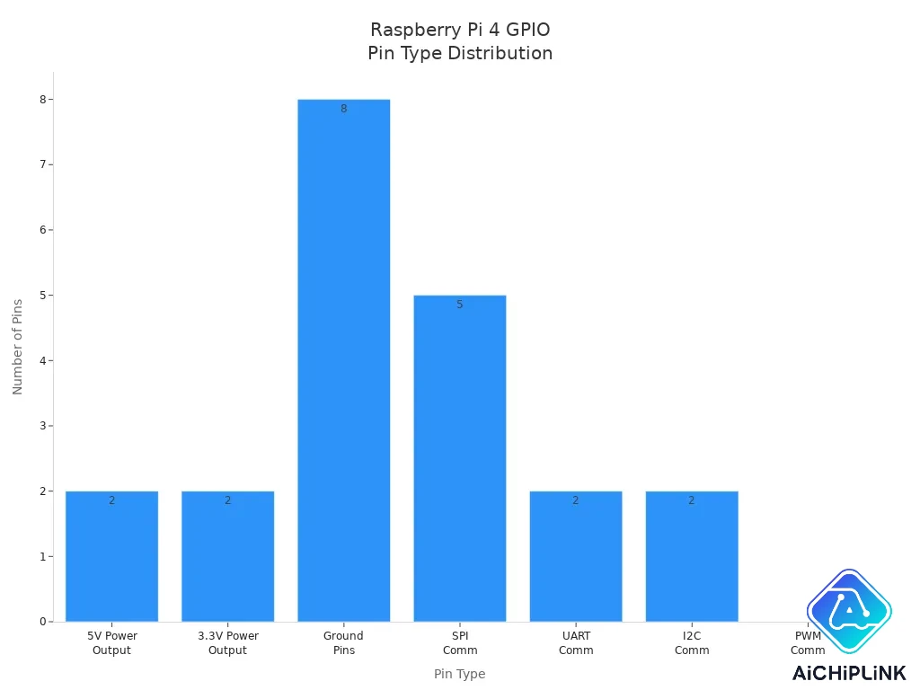
You can see that the raspberry pi 4 pins include many types. The table shows which pins give 3.3V or 5V power, which ones connect to ground, and which ones are for communication like I2C, SPI, and UART. The GPIO pins let you control LEDs, motors, and sensors.
Tip: Always double-check the pinout diagram before you connect anything. This helps you avoid mistakes and keeps your raspberry pi safe.
Key Pin Functions
The raspberry pi 4 pins have different jobs. You use power pins to give energy to your circuits. The 3.3V pins (1 and 17) and 5V pins (2 and 4) supply power to your devices. The ground pins (6, 9, 14, 20, 25, 30, 34, 39) complete the circuit and keep everything safe.
The GPIO pins are the heart of your raspberry projects. You can set these pins to send out signals or read signals from sensors. Some GPIO pins have special uses. For example, pins 3 and 5 work with I2C, pins 8 and 10 work with UART, and pins 19, 21, 23, 24, and 26 work with SPI. You can use PWM pins (like 12, 32, and 33) to control the brightness of LEDs or the speed of motors.
You can see from the chart that the raspberry pi 4 gives you many options for connecting devices. The GPIO header has enough pins for most projects. You can use the same pinout diagram for older raspberry pi models. The raspberry pi 4 keeps the same layout, so your old HATs and accessories will still work.
Note: The raspberry pi 4 pins follow a standard layout. This means you can use guides and diagrams made for older raspberry pi boards. You do not need to change your wiring or code when you upgrade your pi.
You can use the raspberry pi 4 pins for many projects. You can blink LEDs, read sensors, or talk to other devices. The GPIO pins let you control almost anything. The power and ground pins keep your circuits running safely. The pinout diagram is your best friend when you build with raspberry pi.
Raspberry Pi 4 Specs
Hardware Overview
The raspberry pi 4 is a strong and flexible board. It uses a Broadcom BCM2711 chip. This chip has four Cortex-A72 CPU cores at 1.5 GHz. You can buy a raspberry pi 4 with 2GB, 4GB, or 8GB of LPDDR4 memory. The board has a 40-pin GPIO header for connecting things like sensors and switches. There are also dual micro-HDMI ports. You can plug in two monitors and watch clear 4K video. The USB-C port gives power to the raspberry pi 4. It can also send power to your projects through the GPIO pins.
Here is a table that lists the main hardware features:
| Specification Category | Details |
|---|---|
| GPIO Interface | 40-pin GPIO for switches, sensors, ADCs, displays, relays, RTCs, timers, and more |
| Processor | Broadcom BCM2711 SoC, Quad-core 1.5 GHz 64-bit Cortex-A72 CPU |
| Memory | LPDDR4 SDRAM: 2GB, 4GB, or 8GB |
| Video Interfaces | Dual micro-HDMI ports, supports 4K video |
| Power Input | USB-C and GPIO pins |
| Connectivity | USB 3.0, Gigabit Ethernet, WiFi (2.4GHz & 5GHz), Bluetooth 5.0 & BLE |
| DSI Connector | 15-pin display interface |
| CSI Connector | 15-pin camera interface |
| Additional I/O | 3.5mm audio/composite video port |
Tip: The raspberry pi 4 has more memory and a faster processor than older models. This means you can work with more data and try bigger projects.
Connectivity Features
You can hook up many devices to the raspberry pi 4. The GPIO pins let you send and get data from sensors, motors, and screens. The raspberry pi 4 works with I2C, SPI, and UART protocols. These help your pi talk to other boards and modules. You can use Python to program the GPIO pins and control what your raspberry pi 4 does with data.
The GPIO pins use 3.3V logic. You need to use the right voltage to keep your raspberry pi 4 safe. The board also has hardware PWM pins. These pins help you control how fast motors spin or how bright LEDs shine. The table below shows how the raspberry pi 4 connects to different devices:
| Connectivity Feature | GPIO Pins Involved | Description |
|---|---|---|
| PWM (Hardware) | GPIO12, GPIO13, GPIO18, GPIO19 | Makes pulse-width signals for motors and LEDs |
| SPI0 | GPIO7, GPIO8, GPIO9, GPIO10, GPIO11 | Fast data exchange with sensors and displays |
| SPI1 | GPIO16, GPIO17, GPIO18, GPIO19, GPIO20, GPIO21 | Connects more SPI devices for more data options |
| I2C | GPIO0, GPIO1, GPIO2, GPIO3 | Two-wire protocol for sensors and EEPROMs |
| UART | GPIO14, GPIO15 | Serial data communication with other boards |
You can use these features to gather data, control things, and make smart projects. The raspberry pi 4 makes it simple to connect and share data with many electronics.
GPIO and Pin Categories
Power Pins
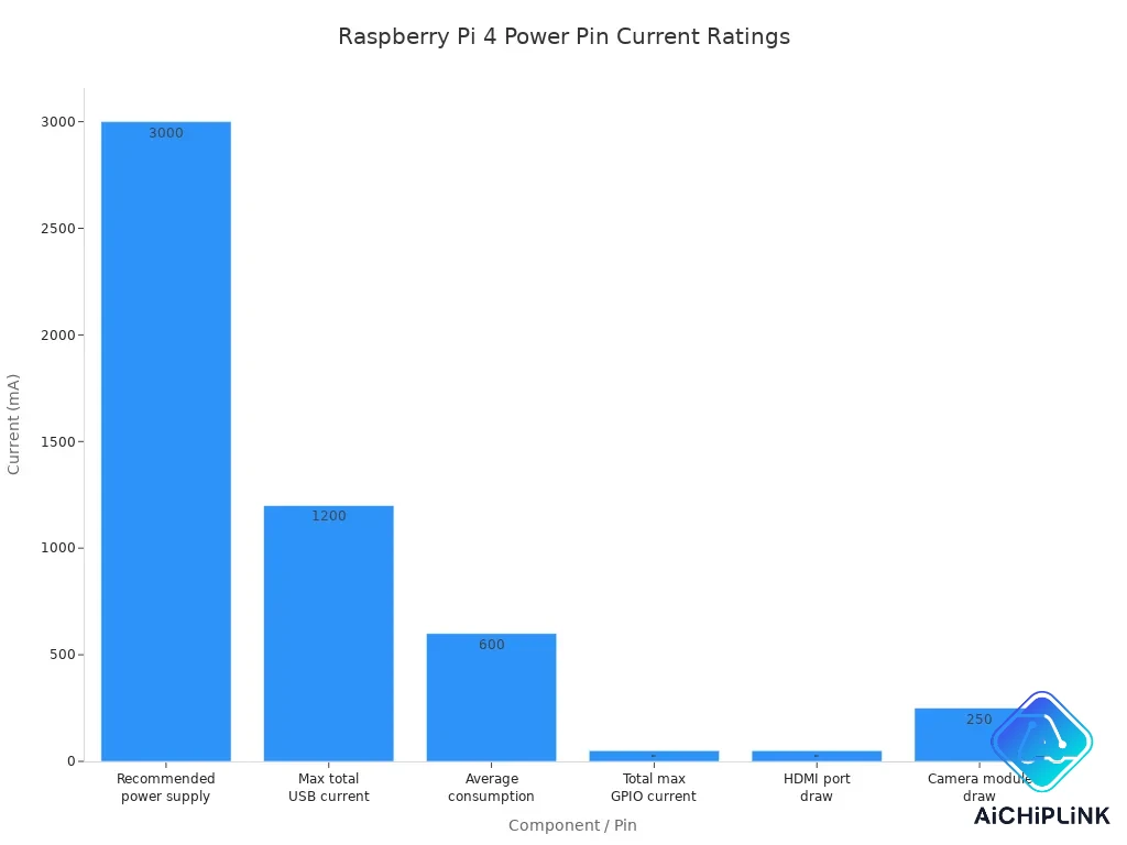
You use the power pins on your Raspberry Pi 4 to supply energy to your circuits. The 5V and 3.3V pins give you two voltage options for different devices. The 5V pins connect directly to your USB-C power supply, so you must never draw more current than your adapter can handle. The 3.3V pins use a regulator that can provide up to 1.5A, but you should keep your current draw lower to avoid overheating. Always check the current needs of your sensors or motors before connecting them to the power pins.
| Parameter | Value |
|---|---|
| Official power supply voltage | 5.1 V |
| Recommended power supply current | 3 A |
| Minimum power supply power | 15.3 W |
| GPIO pin max current per pin | 16 mA (up to 30 mA) |
| Total recommended max GPIO current | 50 mA |
Always use the correct power pins for your devices. Never try to power your Raspberry Pi through the GPIO pins.
Ground Pins
Ground pins complete your circuits and keep your Raspberry Pi safe. You connect the ground pins to the negative side of your components. This helps prevent short circuits and electrical noise. You find several ground pins on the GPIO header, so you can connect multiple devices at once. Always double-check your ground connections before you power up your board.
GPIO Pins
The GPIO pins are the main way you control and read signals from your projects. You can set each gpio pin as an input or output. When you want to turn on an LED or read a button, you use these pins. The gpio pins work at 3.3V logic levels. Never connect them to 5V, or you may damage your board. Each gpio pin can handle up to 16mA, but the total current for all gpio pins should not go over 50mA. If you want to know how to use gpios, start by setting them as outputs for LEDs or as inputs for buttons.
-
Digital I/O: Send or receive digital signals.
-
PWM: Control brightness or motor speed.
-
I2C, SPI, UART: Communicate with other devices.
On boot, all gpio pins start as inputs. Set them as outputs in your code if you want to control devices.
Communication (I2C, SPI, UART, PWM)
You use special pins for communication protocols. The i2c pins (SDA and SCL pins) let you connect sensors and displays using i2c communication. The spi pins help you talk to fast devices like screens or memory chips. The uart pins let you send and receive serial data, which is useful for talking to other computers or microcontrollers. PWM pins let you control things like LED brightness or servo position by changing the signal’s duty cycle.
| Communication Protocol | Supported on Raspberry Pi 4 GPIO | General Pin Functionality |
|---|---|---|
| I2C | Yes | Connects to i2c devices using sda and scl pins. |
| SPI | Yes | Connects to spi devices for fast data transfer. |
| UART | Yes | Sends and receives serial data. |
| PWM | Yes | Controls devices by changing signal duty cycle. |
If you want to learn how to use gpios for these protocols, you can use Python libraries like RPi.GPIO or GPIO Zero. These make it easy to set up i2c, spi, uart, and pwm on the right pins.
Safety Tips
You must follow safety rules when working with gpio pins. Never connect more than 3.3V to any gpio pin. Always use resistors with LEDs and buttons to limit current. Do not connect motors or high-current devices directly to gpio pins. Use a motor driver or relay for these loads. Double-check all wiring before you power on your Raspberry Pi. Avoid making changes while the board is powered. Use a breadboard to test your circuits first.
-
Never exceed 3.3V on gpio pins.
-
Use resistors to protect gpio pins.
-
Avoid direct connections to motors; use drivers.
-
Always check your wiring before turning on the power.
-
Use pull-up or pull-down resistors for stable inputs.
If you follow these tips, you will keep your Raspberry Pi safe and your projects working well.
Raspberry Pi Pinout Projects
LED Blink Example
You can start your raspberry pi gpio projects by blinking an LED. This project helps you learn how to use gpio pins safely. First, gather your parts: a raspberry pi, a breadboard, an LED, a resistor (220Ω–1kΩ), and jumper wires. Make sure your pi is unplugged before you connect anything.
-
Place the LED on the breadboard. Connect the longer leg (anode) to a gpio pin, such as pin 7, through the resistor.
-
Connect the shorter leg (cathode) to a ground pin.
-
Plug in your pi and open a Python IDE.
-
Write a script to set the gpio mode, set the pin as output, and turn the LED on and off with a delay.
import RPi.GPIO as GPIO
import time

GPIO.setmode(GPIO.BOARD)
GPIO.setup(7, GPIO.OUT)

for i in range(5):
    GPIO.output(7, GPIO.HIGH)
    time.sleep(2)
    GPIO.output(7, GPIO.LOW)
    time.sleep(2)
GPIO.cleanup()
Run your script. The LED will blink, showing you how to control gpio pins. This project uses basic gpio, but you can try other pins or add pwm for dimming.
Always use a resistor to protect your LED and gpio pins.
Sensor Reading
You can connect many sensors to your raspberry pi gpio pins. Digital sensors like DHT11 for temperature and humidity work well for beginner projects. You connect these sensors to gpio pins and read data using Python. For analog sensors, you need an ADC chip, because the pi does not have built-in analog input. Many i2c devices, such as displays or environmental sensors, connect to the i2c pins. You can also use spi devices for fast data transfer or uart devices for serial communication. Most beginner projects use digital sensors, which connect directly to gpio pins.
Device Control
You can use your raspberry pi to control external devices like relays or motors. Set gpio pins as outputs to switch relays on or off. For example, connect a relay module to gpio pin 11 and ground. Use Python to control gpio pins and activate the relay. You can use two relays to control a motor’s direction. The table below shows how relay states affect motor action:
| Relay 1 State | Relay 2 State | Motor Action |
|---|---|---|
| OFF | OFF | STOP |
| ON | OFF | Clockwise (CW) |
| OFF | ON | Counter-Clockwise (CCW) |
| ON | ON | STOP |
You can also use pwm pins to control motor speed or LED brightness. Many projects use i2c devices or spi devices for more advanced control. Always check the voltage and current limits of your gpio pins before connecting devices.
Troubleshooting
If your raspberry pi gpio projects do not work, follow these steps:
-
Run a gpio test program with
sudo pigpiodto check for hardware problems. -
Disconnect all external devices from the gpio pins during testing.
-
Check your wiring and make sure each component is in the right place.
-
Confirm LED polarity and resistor placement.
-
Run your Python scripts with
sudoto get gpio access. -
Check your code for errors in syntax or indentation.
-
Use a multimeter to test components and breadboard connections.
-
Review example scripts and adjust input handling if needed.
-
Always double-check your gpio pin numbers and connections.
-
Use pull-up or pull-down resistors for stable inputs.
-
If a gpio pin fails with nothing connected, it may be damaged.
Careful setup and testing help you build safe and reliable raspberry pi projects.
Raspberry Pi 4 Datasheet
Where to Find It
You can get the official Raspberry Pi 4 datasheet from trusted sites. The datasheet has all the technical info you need for your projects. Here are some places where you can find it:
-
The Raspberry Pi official docs site has a datasheets section at https://datasheets.raspberrypi.com.
-
The Raspberry Pi 4 Model B product page lists datasheets and technical info. You can go to https://www.raspberrypi.org/products/raspberry-pi-4-model-b/.
-
The main docs portal at https://www.raspberrypi.com/documentation/ has hardware guides and links to datasheets.
You should always use the official datasheet to get the best info about your Raspberry Pi 4. This helps you not make mistakes when you connect new parts or plan your circuits.
Tip: Save the datasheet page as a bookmark. This way, you can check info fast when you build or fix your projects.
How to Use It
The Raspberry Pi 4 datasheet helps you learn about the board’s hardware and pinout. You can use it to check each pin’s info, see power limits, and learn how to connect things safely. The datasheet lists the 40-pin GPIO header. It shows each pin’s number, name, and job. This makes it simple to match your wires to the right pins.
Here is a table with some important info you will find in the datasheet:
| Component | Details |
|---|---|
| SoC | Broadcom BCM2711, Quad core Cortex-A72 64-bit SoC @ 1.5GHz |
| Memory | Up to 4GB LPDDR4-2400 SDRAM (model dependent) |
| Connectivity | Gigabit Ethernet; 2 USB 3.0 ports; 2 USB 2.0 ports |
| Power Interface | USB-C connector |
| CPU Improvements | Larger L1/L2 caches, out-of-order pipeline, higher clock speed |
| USB 3.0 Details | Full duplex, shares PCIe Gen2 bandwidth among all USB ports |
| Performance Notes | USB 3.0 bandwidth shared across ports, affects device throughput |
You can also use the datasheet to:
-
Check the boot modes and boot order.
-
Find info about the power supply and power button.
-
Learn about the SPI, I2C, and UART pins.
-
Review the electrical info for each GPIO pin.
-
See how data moves for USB and Ethernet ports.
When you build a project, always check the datasheet for the right voltage and current info. This keeps your Raspberry Pi 4 safe and helps your data move well between devices.
Always use a good 5V/3A power supply and handle the board with care. The datasheet will show you the safe limits for each pin and help you stop damage.
The Raspberry Pi 4 pinout has many pins for lots of projects. You can use pwm, power, and ground pins to work with LEDs, motors, and sensors. The pi lets you start with Python and use the pinout map. You can build easy circuits, use the PiCockpit app, or check out pwm and power features.
Always check your raspberry pi pins before you turn it on. This helps stop damage and keeps your raspberry pi working well.
-
Next steps:
-
Get the official datasheet.
-
Try a simple project with pwm or power pins.
-
Look at community guides and raspberry pi forums for more ideas.
-
FAQ
What is the difference between physical pin numbers and BCM numbers?
Physical pin numbers count the pins from 1 to 40 on the board. BCM numbers match the Broadcom chip’s GPIO names. Always check which numbering system your code uses. Using the wrong system can cause wiring mistakes.
Can you connect 5V devices directly to GPIO pins?
No, you cannot connect 5V devices directly to GPIO pins.
GPIO pins use 3.3V logic. Connecting 5V can damage your Raspberry Pi. Use a level shifter or voltage divider for safe connections.
How much current can you draw from a single GPIO pin?
Each GPIO pin can safely provide up to 16mA.
You should keep the total current for all GPIO pins under 50mA. Drawing too much current can overheat or damage your board.
What should you do if your Raspberry Pi does not detect a connected device?
-
Check your wiring for loose or wrong connections.
-
Make sure you use the correct pin numbers.
-
Test your code for errors.
-
Try a different sensor or cable if possible.
Careful troubleshooting helps you find the problem quickly.

Written by Jack Elliott from AIChipLink.
AIChipLink, one of the fastest-growing global independent electronic components distributors in the world, offers millions of products from thousands of manufacturers, and many of our in-stock parts is available to ship same day.
We mainly source and distribute integrated circuit (IC) products of brands such as Broadcom, Microchip, Texas Instruments, Infineon, NXP, Analog Devices, Qualcomm, Intel, etc., which are widely used in communication & network, telecom, industrial control, new energy and automotive electronics.
Empowered by AI, Linked to the Future. Get started on AIChipLink.com and submit your RFQ online today!
Frequently Asked Questions
What is the difference between physical pin numbers and BCM numbers?
Physical pin numbers count the pins from 1 to 40 on the board. BCM numbers match the Broadcom chipâs GPIO names. Always check which numbering system your code uses. Using the wrong system can cause wiring mistakes.
Can you connect 5V devices directly to GPIO pins?
No, you cannot connect 5V devices directly to GPIO pins. GPIO pins use 3.3V logic. Connecting 5V can damage your Raspberry Pi. Use a level shifter or voltage divider for safe connections.
How much current can you draw from a single GPIO pin?
Each GPIO pin can safely provide up to 16mA. You should keep the total current for all GPIO pins under 50mA. Drawing too much current can overheat or damage your board.
What should you do if your Raspberry Pi does not detect a connected device?
Check your wiring for loose or wrong connections. Make sure you use the correct pin numbers. Test your code for errors. Try a different sensor or cable if possible. Careful troubleshooting helps you find the problem quickly.