XOR Logic Gate: Truth Table, Properties, Applications, and Popular ICs

The XOR Logic Gate outputs true only when an odd number of its inputs are true. The two-input truth table shows all combinations:
-
0 XOR 0 = 0
-
0 XOR 1 = 1
-
1 XOR 0 = 1
-
1 XOR 1 = 0
This operation is called exclusive OR. It performs modulo-2 addition. The Boolean expression is Y = A ⊕ B. XOR gates enable parity checking, binary addition, and encryption. They work as controlled inverters and comparators. Multi-input XOR gates produce true when the number of true inputs is odd. This post covers the Boolean expression, multi-input behavior, key properties, practical applications, and popular ICs.
Key Takeaways
-
XOR gives a true output only when its inputs are different. This makes it useful for parity checking and for the sum bit in a half-adder.
-
XOR works the same way no matter how you group or order the gates, so you can move them around and still get the same result.
-
XOR with 0 lets the signal through; XOR with 1 flips it; XOR with itself gives 0.
-
Use ICs like 74HC86 or CD4070 to get four XOR gates; always connect unused inputs to ground.
XOR Logic Gate Symbol and Expression
Standard and IEC Symbols
Engineers draw the XOR Logic Gate in two main notation families. The distinctive-shape style follows ANSI/IEEE practice. It looks like an OR gate with one extra curved arc across the input side. That doubled line tells the reader the output is true for exactly one high input, not for both.
The rectangular style follows IEC practice. It uses a plain rectangle with a qualifier inside, usually the text =1. Both graphics describe the same Boolean relationship, Y = A ⊕ B. The table below compares the two symbol families side by side.
| Gate | ANSI/IEEE Distinctive Shape | IEC Qualifying Symbol | Boolean Expression |
|---|---|---|---|
| XOR | OR shape with a doubled/extra curved line on the input side | Rectangle with =1 qualifier | Y = A ⊕ B |
Boolean Equation Forms
The standard Boolean expression is Y = A ⊕ B = A'B + AB'. This form shows the exclusive OR idea directly. The output is true when exactly one input is true. Two other forms reach the same result using AND, OR, and NOT:
-
p XOR q = (p AND NOT q) OR (NOT p AND q)
A NAND-only version also exists. It follows a short derivation:
-
Start with the standard XOR expression: A'B + AB'.
-
Apply double complement: [(A'B + AB')']'.
-
Apply De Morgan's Law to the inner complement: [(A'B)' · (AB')']'.
-
This yields the NAND-only expression: ((A'B)' · (AB')')' = A'B + AB'.
-
Implementation uses five NAND gates: first NAND gives A', second NAND gives (A'B)', third NAND gives B', fourth NAND gives (AB')', and the fifth NAND combines them to produce ((A'B)'(AB')')'.
Each form suits a different design job. The AND-OR-NOT version reads well in textbooks. The NAND-only version matters when a board already uses NAND packages.
Truth Table for 2-Input and Multi-Input XOR

Two-Input Truth Table
A truth table lists every possible input combination and the matching output. Building one follows a fixed method. First, count the input variables. A two-input gate has two variables, so the total number of combinations is 2 raised to the power of 2, which equals 4. Next, list those combinations in binary order: (0,0), (0,1), (1,0), (1,1). Then apply the gate's logic function to each row.
For the XOR Logic Gate, the rule is simple. The output is 1 only when the inputs differ. The table below shows the full result.
| A | B | Y = A ⊕ B |
|---|---|---|
| 0 | 0 | 0 |
| 0 | 1 | 1 |
| 1 | 0 | 1 |
| 1 | 1 | 0 |
Row one gives 0 because both inputs are low. Rows two and three give 1 because the inputs are different. Row four gives 0 because both inputs are high. This pattern matches the Boolean expression Y = A'B + AB'.
Multi-Input and Odd Parity
A gate with more than two inputs follows a different rule. The output is true when the number of true inputs is odd. A three-input XOR with inputs A, B, and C outputs 1 for the combinations (0,0,1), (0,1,0), (1,0,0), and (1,1,1). Each of those rows has one or three high inputs. Rows with zero or two high inputs produce 0.
This behavior makes the gate a natural odd parity checker. In a simulation tool such as Logisim, a multi-input XOR block can be set to odd parity mode. The gate then outputs 1 whenever an odd number of its inputs are high. Error detection systems use this trait to flag a corrupted bit stream.
XOR also performs modulo-2 addition, which is binary addition without carry. The sum bit and the XOR output match for every input pair, as the chart below confirms.
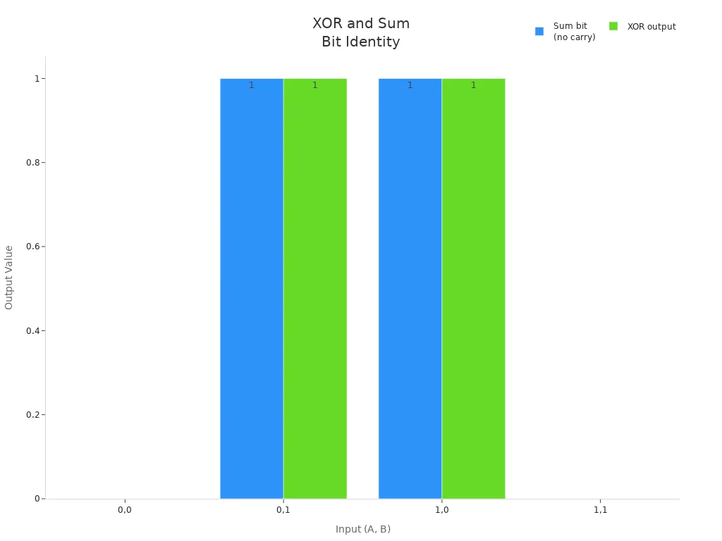
Modulo-2 addition of two bits has the same truth table as XOR.
This link explains why XOR supplies the sum output of a half adder. The AND gate supplies the carry output in that same circuit. A full adder extends the idea by adding a carry-in. Multi-bit adders then connect or predict carries across bit positions. The relationship between XOR and sum-without-carry holds exactly, even when a physical arithmetic logic unit uses different cells or transistor networks to build it.
XOR Logic Gate Properties
Associativity and Commutativity
With XOR, you can rearrange the inputs and still get the same answer. That property is commutativity. A ⊕ B always gives the same result as B ⊕ A. You can also group them in different ways. That property is associativity. (A ⊕ B) ⊕ C always gives the same result as A ⊕ (B ⊕ C).
These two properties help when building a parity tree. A parity tree checks if a data stream has an odd or even number of 1s. Designers can put the gates in any order and still get the right result. The structure stays flexible during design and optimization.
XOR is associative and commutative, so the order of XOR operations does not change the final result. This property helps when building a branching program for the parity function. By applying XOR one by one to the inputs, you can track parity efficiently. That leads to a solution with only O(n) nodes.
Identity, Complement, and Odd Function
Three simple rules tell how the XOR gate works with constants and with itself. The table below shows each case.
| Expression | Meaning | Output behavior |
|---|---|---|
| A ⊕ 0 | XOR with constant 0 | Pass-through: output equals A |
| A ⊕ A | XOR with itself | Forced zero: output is always 0 |
| A ⊕ 1 | XOR with constant 1 | Conditional inverter: output equals NOT A |
These rules are used in real circuits. XOR with 0 works as a pass-through in adder/subtractor circuits. A control bit can turn the same XOR into an inverter. XOR with itself gives 0, which helps in parity and error detection. XOR with 1 works as a conditional NOT, a pattern used in ciphers like AES and DES.
The odd function property works for any number of inputs. The output is 1 when an odd number of inputs are 1. This "odd detector" nature is true for two inputs, three inputs, or more. Inverting an odd number of inputs turns XOR into XNOR. Inverting an even number does nothing.
XOR Logic Gate Applications
Parity, Addition, and Comparators
Parity checking is one of the most common uses of the XOR gate. A parity checker lines up XOR gates across the data bits. The gate gives 0 when its two inputs are the same and 1 when they are different. This action shows whether a pair holds an even or odd number of 1s. For an 8-bit word plus one parity bit, all data bits are XORed together to find the overall parity. That result is then XORed with the received parity bit. To make an even parity bit, all data bits are XORed together. The resulting bit makes the total count of 1s even. To check even parity at the receiver, all received bits are XORed together. A result of 0 means the parity check passes. A result of 1 marks an error. For example, sending data 1 0 1 1 (three 1s, odd) needs a parity bit of 1 to make the total even. The sent word becomes 1 0 1 1 1. XORing all five bits gives 0, which shows no error. If the second bit flips, the received word becomes 1 1 1 1 1, and XORing all bits gives 1, which marks an error. This method finds single-bit errors. It cannot tell which bit flipped, and it fails to find any even number of flipped bits.
Binary addition also depends on XOR. The simplest half-adder design uses an XOR gate for the sum and an AND gate for the carry. The sum is 1 when the two inputs differ and 0 when they match. An XOR gate makes the Sum (S) output, while an AND gate makes the carry. A half adder adds two single-bit inputs, A and B, with no carry-in from a earlier stage. The sum follows Sum = A XOR B. A full adder builds on this idea by adding a carry-in.
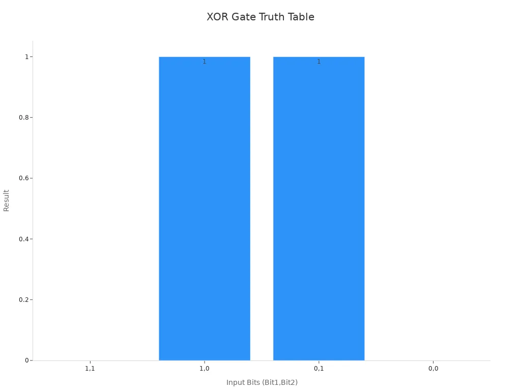
Comparators use XOR to test whether two binary numbers are equal. Same bits give 0, so XORing two equal numbers gives 0. The table below shows this bitwise comparison.
| Bit in Number 1 | Bit in Number 2 | XOR Result |
|---|---|---|
| 1 | 1 | 0 |
| 1 | 0 | 1 |
| 0 | 1 | 1 |
| 0 | 0 | 0 |
Inside a microprocessor, the arithmetic logic unit uses XOR in two ways. It works as a selectable bitwise logic operation, and it acts as a controlled inversion mechanism inside the adder/subtractor. For subtraction, the ALU changes B using an XOR control bit. When SUB = 0, the adder computes A + B. When SUB = 1, it computes A + B̄ + 1, which equals A − B.
A Boolean Unit is dedicated to boolean operations such as XOR, bit masking, and similar tasks.
Encryption and Controlled Inverter
XOR is a key part in stream ciphers. A keystream comes from a pseudo-random number generator, and the resulting cipher is a stream cipher. The one-time pad also relies on XOR. With a truly random key, the result is theoretically unbreakable. The XOR cipher uses XOR as its main operation. A constant repeating key can be broken through frequency analysis. More complex ciphers use XOR as a common building block.
XOR Encryption is an extremely common component used in more complex encryption algorithms used nowadays, due to its effectiveness and simplicity.
The XOR gate also works as a controlled inverter. This behavior comes from the property A ⊕ 1 = A'. When one input is held at logic 1, the output becomes the inverse of the other input. Setting the control input to 1 inverts the signal on the data input. A real example is staircase wiring, where a lamp turns on or off from two different switches. Microcontroller-based signal processing also uses XOR. One early hardware circuit used an RC timing value, a flip-flop, and an XOR gate for Manchester decoding.
Popular XOR ICs and Usage Tips
74LS86, 74HC86, CD4070, and 74HCT86
Four chips cover most hobby and production needs. The 74HC86 is a high-speed CMOS quad 2-input XOR gate. The 74LS86 is a low-power Schottky quad 2-input XOR gate. The CD4070 is a quad 2-input XOR gate from the 4000-series CMOS family. The 74HCT86 is a high-speed CMOS part with TTL-compatible inputs. Each package holds four independent gates, so one chip handles a full 4-bit parity task.
The CD4070 pinout shows the standard 14-pin layout. Power sits on pin 14, and ground sits on pin 7.
| Pin Name | Pin # | Type | Description |
|---|---|---|---|
| VDD | 14 | Power | Supply Voltage (+3 to +15V) |
| GND | 7 | Power | Ground (0V) |
| A1 to A4 | 1, 5, 8, 12 | Input | Inputs A of the four XOR gates |
| B1 to B4 | 2, 6, 9, 13 | Input | Inputs B of the four XOR gates |
| Q1 to Q4 | 3, 4, 10, 11 | Output | Outputs from the four XOR gates |
A designer can also build an XOR Logic Gate from three NAND gates and two inverters. That trick helps when a board already stocks NAND packages.
Wiring and Troubleshooting Tips
Breadboard builds fail for predictable reasons. A DIP switch that stops making contact leaves an input floating, and the output then reads wrong. A jumper wire can look fine yet fail to conduct inside. Messy wiring hides these faults, so color-coding helps: green for inputs, yellow for XOR outputs, blue for carry-outs, red and black for power.
Test each gate against its expected levels before trusting the circuit.
| Input A | Input B | Expected Output |
|---|---|---|
| LOW (0 V) | LOW (0 V) | LOW (0 V) |
| LOW (0 V) | HIGH (Vcc) | HIGH (Vcc) |
| HIGH (Vcc) | LOW (0 V) | HIGH (Vcc) |
| HIGH (Vcc) | HIGH (Vcc) | LOW (0 V) |
Keep these limits in mind:
-
Input pins draw very little current, especially in CMOS gates.
-
Output pins source or sink only limited current, so they suit logic inputs or LEDs with current-limiting resistors.
-
These gates should not directly drive motors or relays.
-
Exceeding voltage or current limits can damage the gate.
If an input is floating, the XOR output may behave unpredictably. Inputs should always be connected to a defined HIGH or LOW level to avoid noise and errors.
Always check the datasheet for pinouts and voltage levels before powering up.
The XOR Logic Gate is special because of how it handles odd parity. Its truth table is easy to follow: two inputs that are the same give 0, and two inputs that are different give 1. This unusual action makes real circuits work. Parity checkers use it to find single-bit errors. Half adders use it to create sum bits. Comparators use it to check if values are equal. Encryption systems depend on it as a basic building block. The properties of XOR make all these uses possible.
You can try these ideas out on a breadboard. Common ICs include the 74HC86 and CD4070. Both have four separate 2-input gates. Connect the power pins the right way, then check each output using the truth table. Always look at the datasheet for the exact pinout and suggested voltage levels before you power up.

Written by Jack Elliott from AIChipLink.
AIChipLink, one of the fastest-growing global independent electronic components distributors in the world, offers millions of products from thousands of manufacturers, and many of our in-stock parts is available to ship same day.
We mainly source and distribute integrated circuit (IC) products of brands such as Broadcom, Microchip, Texas Instruments, Infineon, NXP, Analog Devices, Qualcomm, Intel, etc., which are widely used in communication & network, telecom, industrial control, new energy and automotive electronics.
Empowered by AI, Linked to the Future. Get started on AIChipLink and submit your RFQ online today!
Frequently Asked Questions
What does XOR stand for and how is it different from OR?
XOR stands for exclusive OR. It outputs 1 only when inputs differ. Standard OR outputs 1 when any input is 1. XOR outputs 0 when both inputs are 1.
Can I build an XOR gate from other logic gates?
Yes. You can build XOR from three NAND gates and two inverters. The NAND-only version helps when a board already uses NAND packages. Other constructions use AND, OR, and NOT gates.
Why does XOR work for binary addition?
XOR performs modulo-2 addition without carry. The sum bit of a half adder equals A XOR B. AND handles the carry output. This relationship extends to full adders and multi-bit addition.
What happens if an XOR gate input is left unconnected?
A floating input creates unpredictable output. Noise causes the gate to switch randomly. Always connect every input to a defined HIGH or LOW level. This rule applies to all CMOS logic gates.
How does XOR detect errors in data transmission?
XOR compares data bits against the parity bit. The final output tells if the total count of 1s matches expectations. A result of 0 means no single-bit error. A result of 1 flags an error.