The ic 7490 decade counter operates as a digital device that performs counting in decimal form. Engineers use the 7490 for counting from 0 to 9, as it functions as a 4-bit BCD asynchronous counter. The 7490 combines a ripple-type architecture with mod-2 and mod-5 counters to achieve reliable decade counter performance. Its design includes reset pins, which allow users to control the counter’s state. The ic 7490 enables accurate counting in digital systems, making it a preferred choice for applications that require decade counter circuits.
Key Takeaways
-
The IC 7490 is a 4-bit decade counter that counts from 0 to 9 in binary-coded decimal format, making it ideal for digital counting tasks.
-
It uses a ripple counter design with mod-2 and mod-5 sections to achieve accurate and reliable counting with flexible reset and set controls.
-
The IC 7490 operates at 5 volts and can handle counting speeds up to 42 MHz, suitable for high-speed digital applications.
-
Its simple 14-pin layout and clear pin functions make it easy to integrate into circuits like timers, clocks, and frequency dividers.
-
Users can cascade multiple IC 7490 chips to create higher count ranges, enabling versatile use in complex digital systems.
IC 7490 Overview
What is IC 7490
The ic 7490 stands as a classic digital integrated circuit designed for counting applications. Engineers classify it as a 4-bit asynchronous decade counter, often called a ripple counter. The internal structure of the ic 7490 features four master-slave JK flip-flops. These flip-flops connect in series to form two main sections: a divide-by-two and a divide-by-five counter. This arrangement allows the 7490 to perform counting in binary-coded decimal format, making it a reliable bcd counter for digital systems.
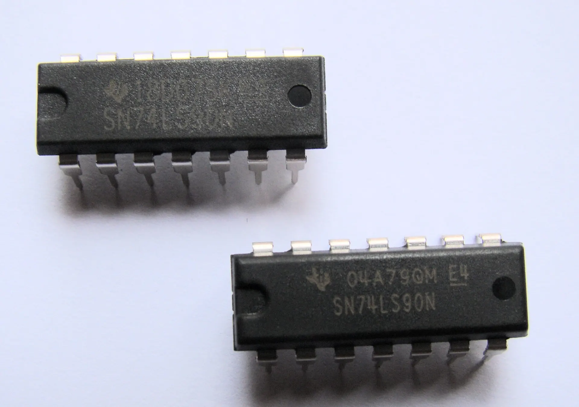
The ic 7490 comes in a 14-pin Dual Inline Package (DIP). It operates at a standard supply voltage of 5 volts and can handle frequencies up to 42 MHz. The device includes dedicated clock inputs (CLKA and CLKB), reset pins (R1-R4), and four outputs (Qa-Qd). These features enable flexible control and easy integration into various counting circuits. Since its introduction, the ic 7490 has played a vital role in digital electronics, supporting applications such as timers, frequency dividers, and digital clocks.
Note: The asynchronous design of the ic 7490 means each flip-flop receives its clock signal from the previous stage, not from a common clock. This ripple architecture simplifies the design but introduces a small propagation delay during counting.
IC 7490 Decade Counter Function
The ic 7490 functions as a decade counter by combining its divide-by-two and divide-by-five sections. This configuration enables the 7490 to count from 0 to 9, then reset to zero, following the binary-coded decimal sequence. The counter advances its state with each clock pulse, producing a unique output for every count. The outputs (Qa, Qb, Qc, Qd) represent the current count in binary form, which can be decoded for display or further processing.
| Feature/Specification | Description |
|---|---|
| Counting Modes | Divide-by-two and divide-by-five (BCD/decade) |
| Counting Range | 0 to 9 in BCD mode |
| Number of Flip-Flops | 4 master-slave JK flip-flops |
| Gated Inputs | Gated zero reset and set-to-nine inputs |
| Count Frequency | Up to 42 MHz |
| Supply Voltage | 5 volts |
| Applications | Digital counters, timers, clocks, frequency dividers |
The ic 7490 supports gated reset and set inputs, allowing users to clear the counter or preset it to a specific value. This flexibility makes the 7490 suitable for a wide range of digital counting tasks. Its monolithic integration ensures reliability and reduces circuit complexity. The ic 7490 remains a preferred choice for building bcd counter circuits, frequency dividers, and digital display drivers.
7490 Datasheet
Electrical Specs
The ic 7490 stands out as a reliable digital counter for many electronic projects. This device operates with a standard supply voltage of 5V, which matches TTL logic levels. The 7490 can handle a maximum count frequency of up to 42 MHz, making it suitable for high-speed applications. Power dissipation remains low, which helps prevent overheating during continuous operation. The ic 7490 features input clamp diodes that protect the internal circuitry from voltage spikes. Its ripple counter architecture uses four JK flip-flops to deliver accurate binary-coded decimal counting.
The table below summarizes the main datasheet parameters for the ic 7490:
| Parameter | Description |
|---|---|
| Supply Voltage | 5V (TTL standard) |
| Count Frequency | Up to 42 MHz |
| Power Dissipation | Low, suitable for continuous operation |
| Counting Modes | Mod-2 and Mod-5 (BCD/decade) |
| Input Clamp Diodes | Yes, for input protection |
| Ambient Temperature | 0°C to 70°C (typical operating range) |
| Internal Circuit | Ripple counter with 4-bit output |
| Operational Details | Asynchronous operation, frequency division, BCD counting |
The ic 7490 supports both mod-2 and mod-5 counting modes. This flexibility allows the 7490 to function as a decade counter or as a frequency divider. The ic 7490 truth table shows how the outputs change with each clock pulse, providing a clear view of its operation.
Package and Pinout
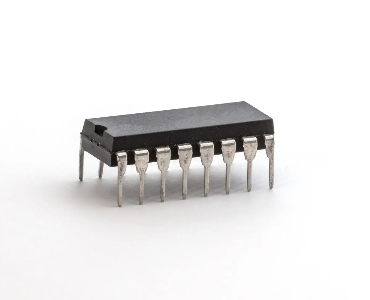
Manufacturers typically offer the ic 7490 in a 14-pin Dual Inline Package (DIP). This package makes it easy to use the 7490 on breadboards and printed circuit boards. The pin configuration includes dedicated inputs for clock and reset, as well as four output pins for the binary count.
The following table lists the pinout for the ic 7490:
| Pin Number | Pin Label | Function Description |
|---|---|---|
| 1 | Reset 2 | Reset input for counter stage 2 |
| 2 | Reset 1 | Reset input for counter stage 1 |
| 3 | Clock B | Clock input for divide-by-two counter |
| 4 | Clock A | Clock input for divide-by-five counter |
| 5 | QA | Output flip-flop A (Least Significant Bit) |
| 6 | QB | Output flip-flop B |
| 7 | GND | Ground connection |
| 8 | QC | Output flip-flop C |
| 9 | QD | Output flip-flop D (Most Significant Bit) |
| 10 | Vcc | Positive power supply |
Tip: Always connect the GND and Vcc pins correctly to ensure proper operation of the ic 7490. The reset pins allow users to clear the counter or set it to a specific value as needed.
The clear labeling of pins on the ic 7490 helps users design circuits quickly. The 7490’s straightforward pinout supports easy integration into digital systems, making it a popular choice for students and engineers.
IC 7490 Working
Ripple Counter Operation
The IC 7490 operates as an asynchronous, or ripple, counter. Its internal structure uses four master-slave JK flip-flops connected in series. The first flip-flop receives the clock pulse through the CLKA input. The output from this flip-flop then triggers the next flip-flop, and so on. This arrangement creates a ripple effect, where each stage changes state based on the output of the previous stage rather than a shared clock.
This ripple architecture means the IC 7490 does not update all outputs simultaneously. Instead, each flip-flop toggles after a small delay, known as propagation delay. This delay is typical in asynchronous counters and can affect the accuracy at very high frequencies. However, for most digital applications, the delay remains negligible.
The IC 7490’s asynchronous design allows it to count quickly and efficiently. The block diagram and truth tables in technical documentation show how each clock pulse advances the counter by one step. The outputs (QA, QB, QC, QD) represent the current count in binary-coded decimal form. The IC 7490 working principle relies on this ripple effect to achieve reliable decade counting.
Note: The ripple counter operation makes the IC 7490 ideal for applications where simple, robust counting is needed, such as event counters and frequency dividers.
Mod-2 and Mod-5 Counters
The IC 7490 contains two main sections: a divide-by-two (mod-2) counter and a divide-by-five (mod-5) counter. The mod-2 section uses one flip-flop, while the mod-5 section uses three flip-flops. The CLKA input drives the mod-2 section, and the CLKB input drives the mod-5 section.
When a clock pulse enters the CLKA pin, the mod-2 section toggles its state. The output from this section then feeds into the mod-5 section through the CLKB pin. The mod-5 section advances its count with each pulse from the mod-2 output. This combination allows the IC 7490 to count from 0 to 9, completing one full cycle for every ten input pulses.
The decade counter function results from this dual-section design. The IC 7490 can also be configured for other counting modes by changing the connections of the clock and reset pins. For example, users can cascade multiple 7490 counters to create higher-order counters, such as mod-100 or mod-1000, by connecting the output of one IC to the clock input of the next.
-
The IC 7490 achieves mod-10 counting by combining its mod-2 and mod-5 sections.
-
The counter advances with each clock pulse, producing a unique binary output for every count.
-
The IC 7490 can drive display circuits, such as 7-segment displays, using decoder/driver ICs.
This flexible design makes the IC 7490 a popular choice for digital clocks, timers, and other applications that require accurate decade counting.
Reset and Set Functions
The IC 7490 includes reset and set pins that provide control over the counter’s state. The reset pins (R0, R1) and set pins (S0, S1) allow users to clear the counter or preset it to a specific value. Applying a high signal to the reset pins resets the counter to 0000. This action clears all outputs, preparing the counter for a new counting sequence. Applying a low signal to the set pins presets the counter to 1001, which represents the decimal value 9.
The reset and set functions operate asynchronously. This means the counter responds to these signals immediately, regardless of the clock pulse. The technical documentation describes these functions in detail, showing how they help control the counting process. Designers use these features to synchronize multiple counters or to start counting from a specific value.
The IC 7490’s reset and set capabilities make it easy to integrate into complex digital systems. Users can quickly clear the counter or set it to a desired value, ensuring reliable operation in a wide range of applications.
Tip: Always use the reset and set pins to initialize the IC 7490 before starting a new counting operation. This practice ensures accurate and predictable results.
The IC 7490 working mechanism, with its ripple counter operation, mod-2 and mod-5 sections, and flexible reset/set functions, provides a robust solution for decade counting in digital electronics. The combination of these features allows the 7490 to serve as a reliable counter in many practical circuits, from simple event counters to advanced digital clocks.
BCD Counter Circuits
Basic Counter Circuit
Engineers often use the ic 7490 to build a basic bcd counter for digital projects. The 7490 operates as a decade counter by combining its internal MOD-2 and MOD-5 sections. When a clock pulse enters the CLKA input, the counter advances its state. The outputs (Qa, Qb, Qc, Qd) display the current count in binary-coded decimal form. Designers can connect LEDs or a seven-segment display to these outputs to visualize the counting process.
The following table shows the pinout for a typical 7490 setup:
| Pin Number | Pin Name | Function Description |
|---|---|---|
| 1 | CLKB | Clock Input 2 |
| 2 | R1 | Reset 1 |
| 3 | R2 | Reset 2 |
| 4 | NC | Not Connected |
| 5 | Vcc | Positive Supply Input |
| 6 | R3 | Reset 3 |
| 7 | R4 | Reset 4 |
| 8 | Qc | Output Pin 3 |
| 9 | Qb | Output Pin 2 |
| 10 | Gnd | Ground |
| 11 | Qd | Output Pin 4 |
| 12 | Qa | Output Pin 1 |
| 13 | NC | Not Connected |
| 14 | CLKA | Clock Input 1 |
The ic 7490 supports high-speed counting up to 42MHz and operates at 5V. Its low power dissipation and flexible reset pins make it ideal for many counting applications.
Frequency Divider Example
The 7490 also serves as a reliable frequency divider in digital circuits. By wiring the ic 7490 in a specific configuration, users can divide an input frequency by 5 or 10. For example, in a phase-locked loop frequency multiplier circuit, the 7490 divides the frequency of an incoming signal, ensuring stable operation. Engineers often use a transistor to drive the ic 7490 when handling higher frequencies. The 7490’s internal ripple counter structure allows it to maintain accuracy and speed, making it suitable for frequency division tasks in clocks and timing circuits.
The 7490’s versatility as a frequency divider supports its use in both simple and advanced digital designs. Its ability to handle high-speed signals and provide consistent output makes it a preferred choice for frequency-related counting applications.
Common Applications
The ic 7490 finds use in a wide range of counting applications. Designers use the 7490 in digital clocks, where it counts seconds, minutes, and hours. Timers and event counters also rely on the 7490’s decade counter function to track occurrences or measure time intervals. In laboratory instruments, the bcd counter helps display measured values in a readable format. The 7490’s robust design and flexible configuration options make it a staple in educational kits and prototyping boards.
Tip: The ic 7490’s straightforward operation and reliable performance make it an excellent choice for anyone learning about digital counting circuits.
The ic 7490 stands as a trusted choice for digital electronics projects. Engineers and students rely on the 7490 for accurate counting in clocks, timers, and display systems. This counter offers dependable performance and simple integration. Many use the 7490 to learn about digital logic and circuit design. Key benefits include:
-
Reliable decade counter operation
-
Flexible use in both learning and real-world applications
-
Easy setup for various counting needs
Experimenting with the ic 7490 helps users gain practical skills in digital electronics.
FAQ
What is the main function of the IC 7490?
The IC 7490 acts as a decade counter. It counts from 0 to 9 in binary-coded decimal (BCD) format. Engineers use it in digital clocks, timers, and frequency dividers.
Can the IC 7490 be cascaded for higher counts?
Yes. Designers can connect multiple IC 7490 chips in series. This setup allows counting beyond 9, such as in mod-100 or mod-1000 counters for advanced applications.
How do the reset pins work on the IC 7490?
The reset pins clear the counter outputs to zero. When activated, these pins immediately set all outputs (Qa, Qb, Qc, Qd) to 0, regardless of the clock input.
What voltage does the IC 7490 require?
The IC 7490 operates at a standard 5V supply voltage. This value matches TTL logic levels, making it compatible with most digital circuits.
Written by Jack from AIChipLink.
AIChipLink, one of the fastest-growing global independent electronic components distributors in the world, offers millions of products from thousands of manufacturers, and many of our in-stock parts is available to ship same day.
We mainly source and distribute integrated circuit (IC) products of brands such as Broadcom, Microchip, Texas Instruments, Infineon, NXP, Analog Devices, Qualcomm, Intel, etc., which are widely used in communication & network, telecom, industrial control, new energy and automotive electronics.
Empowered by AI, Linked to the Future. Get started on AIChipLink.com and submit your RFQ online today!