Why Pull-up and Pull-down Resistors Are Crucial for Microcontroller Inputs
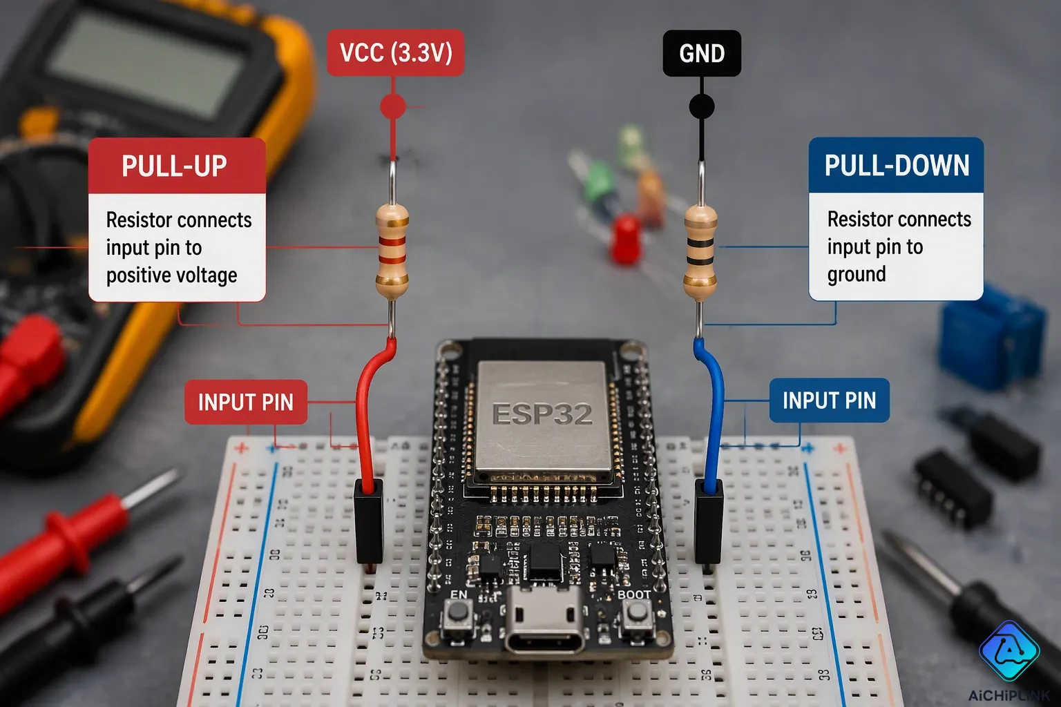
Imagine you connect a push button to a microcontroller input pin. The button works fine sometimes, but other times it registers a press when you haven't touched it. This erratic behavior is frustrating. The root cause is a floating input state. Without pull up and pull down resistors, the pin's voltage is undefined. Electromagnetic noise can push the logic level to high or low randomly. A pull-up resistor connects the input to VCC, ensuring a high default. A pull-down resistor connects to ground for a low default. These components provide a stable logic level. This simple fix is foundational for reliable digital logic circuits. Understanding pull-up and pull-down configurations is essential for any microcontroller project.
Key Takeaways
-
Pull-up and pull-down resistors stop floating inputs. They set a clear high or low state. This stops random readings from noise.
-
A pull-up resistor links to VCC. It sets the starting state as high. A pull-down resistor links to ground. It sets the starting state as low.
-
For most digital inputs, use a 10kΩ resistor. This value balances power use and noise protection. Adjust it for your needs.
-
Internal resistors are handy. They save space and money. External resistors offer more control. They handle noise better.
-
These resistors are key for switches and sensors. They also keep communication lines steady. They make sure your projects work reliably.
The Problem of Floating Inputs
What Is a Floating State?
A floating state happens when a microcontroller input pin isn't connected to anything solid. The pin goes into a high-impedance mode where no circuit actively sets its voltage. Think of this pin like a tiny antenna. It picks up random electromagnetic noise from nearby wires, motors, or power lines. A LinkedIn post by Abhijith Electronic Solution says a floating CMOS input pin can have its voltage drift toward mid-supply, around Vcc/2. This occurs because the pin gathers ambient energy.
For TTL logic circuits, a floating input often reads as a logic high. But this reading isn't dependable. Noise-induced shifts of just a few millivolts can flip the state. For CMOS logic, the problem is worse. A floating input causes unclear states and extra power use. The NI article defines the floating state as a high-impedance state where the output disconnects from the line. This state is neither a logic high nor a logic low. Voltages in the undefined zone between valid high and low ranges are invalid under normal operation.
Without a defined path for current flow, Kirchhoff's laws can't specify the voltage at the node. The voltage becomes open to unpredictable changes from ambient electrical noise, leakage currents, and parasitic capacitance. This leads to unreliable logic level readings.
A floating input also causes a hidden issue: increased current draw. A CMOS digital input has very high impedance. When left unconnected, it floats and its logic level becomes undetermined. The floating input tends to build up charge and drift toward the voltage point where the logic level changes. When the input reaches this point, both the high-side and low-side MOSFETs in the input buffer partially turn on. This creates a direct current path from VDD to VSS, known as shoot-through current. The floating input may lose charge after switching, causing it to hover around the change-over point. This repeatedly triggers shoot-through current, leading to higher-than-expected power draw.
Why Pull-up Resistors Are Needed
Without a pull-up resistor, a microcontroller input pin connected to a switch enters a floating state when the switch opens. This leaves the pin open to electrical noise and unpredictable readings. The fix is simple: connect the input to Vdd through a pull-up resistor. The pull-up forces the pin to a defined high logic level when the switch opens. This removes the undefined state and ensures stable, predictable operation.
The electrical principle is straightforward. Digital logic inputs need a defined voltage level to work correctly. When an input is left unconnected, it can self-bias or pick up noise. A pull-up resistor connects the input to Vcc through a high resistance, typically 4.7kΩ to 200kΩ. When the switch is open, the input reads a stable HIGH because the high-impedance input draws negligible current, so almost all Vcc appears at the pin. When the switch closes, the input pulls to ground, and the resistor limits current flow to prevent a short circuit. The pull-up setup guarantees a defined default state and stops false triggering.
A pull-down resistor works similarly. It connects the input to ground, ensuring a low default state. The pull-down resistor ensures a known low logic level when the switch opens. This pull-down setup gives you a stable default low state. Both pull up and pull down resistors provide a stable reference voltage. They stop floating inputs from causing erratic behavior, false triggering, and extra power use. For any microcontroller input connected to a switch or sensor, these resistors are essential parts.
How Pull-up and Pull-down Resistors Fix the Issue
Setting a Known Logic Level
A pull-up resistor sets a clear high state by linking the input pin to VCC through a large resistance. When no outside signal controls the pin, the resistor slowly pulls the voltage up. The input pin uses almost no current, so nearly all of VCC shows up at the pin. This gives a steady high logic level that noise has a hard time changing.
The math behind this comes from a simple voltage divider. An ideal voltage divider formula shows the output voltage as V_out = V_in times R2 divided by (R1 + R2). Here, R1 is the pull-up resistor and R2 is the input pin's internal resistance. Since the input resistance is very large, the output voltage stays close to VCC. A loaded voltage divider formula adds extra outside loads in parallel with R2. This real-world case matters when the pull-up resistor must set a logic level for a device that uses current. The loaded formula shows that as long as R1 stays much smaller than the load resistance, the voltage stays within valid high limits.
A pull-down resistor works the other way. It connects the input pin to ground, making sure the default state is low. When the switch is open, the gate input voltage drops to ground level. The pull-down resistor keeps the logic signal near zero volts as it pulls the input voltage down to ground. This stops an unclear state at the input.
When the switch is open, the gate input voltage drops to ground level. The pull-down resistor keeps the logic signal near zero volts (0 V) as it pulls the input voltage down to ground to stop an unclear state at the input.
Both setups give you a known logic level before any outside signal arrives. This known state is the base of reliable digital logic circuits. Without this clear state, your microcontroller cannot tell a real signal from random electrical noise.
Internal vs External Resistors
Many modern microcontrollers have built-in resistors you can turn on with software. These internal choices save you from adding extra parts to your circuit board. The table below shows how these setups work.
| GPIO Input Configuration | Function |
|---|---|
| Pull-up | Connects an internal resistor to VCC, which sets a default HIGH logic level on the pin when it is not being actively driven by an outside signal. |
Instead of a physical resistor, microcontrollers often use a PMOS transistor between the pin and VDD. This transistor turns on weakly to act like a high-value resistor, gently pulling the pin's voltage HIGH to set the default state and stop it from floating.
The resistance values for these internal choices vary by maker. STM32 microcontrollers give internal pull-up resistors in the 30–50 kΩ range, with a typical value of 40 kΩ. Arduino boards based on AVR chips, like the Uno or Nano, offer internal pull-ups around 20 kΩ. These values are not exact. They can change between individual chips and shift with temperature or supply voltage.
Internal resistors work fine for many uses, but they have limits. The weak pull strength means they cannot beat strong noise sources or drive long cable runs reliably. External pull-up and pull-down resistors give you exact control over resistance values. You can pick a stronger pull for noisy places or high-speed communication lines. You can also choose a weaker pull for battery-powered projects where saving current matters.
External resistors also give you flexibility that internal choices lack. Some microcontrollers only offer internal pull-ups without matching pull-downs. Adding an external pull-down resistor gives you the opposite default state when your design needs it. For communication protocols like I2C, external pull-up resistors are required because the bus spec needs specific resistance values that internal choices cannot match.
The choice between internal and external resistors depends on your project needs. Start with internal options for simple switch inputs. Move to external resistors when you need exact values, stronger drive, or pull-down function that your microcontroller does not have inside.
Practical Applications of Pull-up and Pull-down Resistors
Using with Switches and Buttons
You hook up a push button to a GPIO pin using a pull-up resistor. When the button is not pressed, the input reads HIGH. When you press the button, it connects the pin to ground, so the input reads LOW. This easy setup gives you a clean, steady signal every time.
Mechanical switches have a hidden problem called contact bounce. When you press a button, the metal contacts shake for a brief period, causing quick ON/OFF changes that the microcontroller reads as many presses. You can fix this with an RC network, such as a pull-up resistor and a capacitor, which creates a time constant that smooths out the bounce. Your microcontroller gets one clean change from HIGH to LOW instead of many false triggers.
Default States for Sensors and Communication Lines
Sensors with open-collector outputs need pull-up resistors to work right. Think about a hall-effect switch used in flow sensing. When the sensor detects a magnetic field, its output transistor turns ON and pulls the signal line to ground. When not active, the transistor turns OFF, leaving the line in a high-impedance state. Without a pull-up resistor, this line floats and picks up electromagnetic noise. The pull-up resistor sets a clear HIGH state when the sensor is idle. Your microcontroller always sees a correct logic level: HIGH when inactive, LOW when active. This stops erratic behavior and wrong pulse counts.
Industrial automation systems have similar problems. A pull-down resistor connects an input pin to ground, setting a clear LOW state when the input is idle. This stops floating states that cause unstable readings and false triggers in noisy factory settings.
The I2C communication bus also needs pull-up resistors. I2C devices use open-drain outputs that can only pull the line LOW. When no device pulls the line down, the bus would float without a clear HIGH state. Pull-up resistors give that HIGH level when the bus is idle. Internal pull-ups often do not work well here. At higher speeds, the rise time can become significant, potentially affecting the signal integrity. External resistors with appropriate values make signal quality much better, allowing reliable communication at standard speeds. These resistors also stop short circuits when many devices drive the line at the same time.
Reset lines on microcontrollers also use pull-up resistors. This makes sure the reset pin stays HIGH during power-up, stopping accidental resets. Pull-up and pull-down resistors protect your whole system from undefined states during power-up or when sensors disconnect.
Selecting Pull-up and Pull-down Resistor Values
Power vs Noise Trade-offs
Picking the right resistor value means balancing two needs. A lower resistance makes a strong pull that fights noise well. This strength costs more current through the resistor, wasting power. A higher resistance saves energy but leaves your input more open to noise. You must decide which factor matters more for your project.
The table below shows the key factors that guide your choice.
| Factor | Description | Effect on Resistor Value |
|---|---|---|
| Input Impedance | Pull-up should be 1/10th of input impedance to ensure a high logic level. | Use a value within the typical range of 4.7kΩ to 200kΩ for typical MCU inputs. |
| Current Limitation | When button is pressed, resistor limits current; lower value increases current and power. (Ohm's law: R = V/I). | Adjust based on acceptable current and power. |
| Switching Speed | Pull-up resistor and pin capacitance form an RC filter; higher resistance slows response. | Fast signals need lower values, such as 4.7kΩ or lower. |
| Practical Rule | A typical value within the range 4.7kΩ to 200kΩ is a good starting point for most applications. | Adjust based on speed and power needs. |
Common Values and Calculation Examples
You will see that some resistor values show up often in circuit designs. A 10kΩ pull-up resistor works well for general digital inputs. For I2C communication lines, you usually pick a value within the typical range, often 4.7kΩ or lower. Noisy or high-speed places need stronger pulls, so you might choose a lower value. Battery-powered devices often use higher values to save current.
You can find the maximum pull-up resistor value by considering the required rise time and bus capacitance, ensuring the input voltage reaches the high threshold within the specified time. Always check your microcontroller's datasheet for voltage thresholds and rise time requirements.
Your pull-down resistor value follows similar logic. You want a strong enough pull to keep a stable low state without wasting current. Start with 10kΩ for most pull-down uses. Lower it if noise becomes a problem or raise it if power matters more. Always check your microcontroller's datasheet for input leakage current before finalizing your choice.
Pull-up and pull-down resistors stop floating states and make sure logic level readings are dependable. You now know how they set default states, help switches and sensors, and keep communication lines safe. Choosing values means balancing power use and noise protection. Industry advice often recommends a value within the typical range of 4.7kΩ to 200kΩ as a starting point. Use lower values for long cables to combat noise, and higher values for low-power designs. Always check your datasheet for input current details. You can check your pull-up resistor connection with a multimeter in resistance mode. Measure between the input pin and Vcc to make sure the reading matches the resistor's expected value. Start with a typical value for most digital inputs, then change based on your circuit's needs.

Written by Jack Elliott from AIChipLink.
AIChipLink, one of the fastest-growing global independent electronic components distributors in the world, offers millions of products from thousands of manufacturers, and many of our in-stock parts is available to ship same day.
We mainly source and distribute integrated circuit (IC) products of brands such as Broadcom, Microchip, Texas Instruments, Infineon, NXP, Analog Devices, Qualcomm, Intel, etc., which are widely used in communication & network, telecom, industrial control, new energy and automotive electronics.
Empowered by AI, Linked to the Future. Get started on AIChipLink and submit your RFQ online today!
Frequently Asked Questions
What happens if I forget to use a pull-up resistor on a switch input?
Your input pin floats. It reads random HIGH or LOW signals. Noise from nearby electronics triggers false readings. A pull-up resistor fixes this problem. It sets a stable HIGH default for your circuit.
How do I choose between an internal and an external pull-up resistor?
Use the internal resistor for simple, low-noise circuits. It saves space and cost. Choose an external resistor for noisy environments. I2C communication also needs a precise external value. Internal resistors are too weak for long wires.
Does a pull-down resistor work the same way as a pull-up resistor?
Yes, but it connects to ground. A pull-down resistor keeps the input LOW by default. You press the button to make it HIGH. It prevents floating states. A pull-up resistor does the same thing for a HIGH default.
Why does my button press sometimes register twice?
Mechanical switches bounce. The metal contacts vibrate for a brief period, creating multiple quick ON/OFF signals. A pull-up resistor cannot fix this alone. You need a capacitor or software debounce to smooth the signal.
What resistor value should I start with for a general input?
Start with a value within the typical range for general inputs. It balances power use and noise protection. Check your microcontroller datasheet for input current specifications. Adjust the value if your circuit operates in a noisy or high-speed environment.