SPI vs I2C Interface: Selecting the Right Communication Protocol
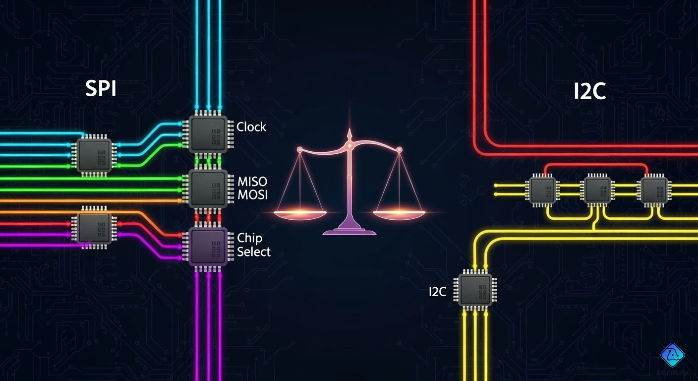
| Metric / Parameter | I2C Protocol | SPI Protocol |
|---|---|---|
| Interface Speeds | 100 kHz, 400 kHz, 1 MHz, 3.4 MHz, up to 5 MHz | 10–50 MHz (no fixed upper limit) |
| Pin Count / Wiring | Fixed 2 shared pins (SDA, SCL) | 4 core lines + 1 CS line per slave |
| Protocol Overhead | High (address bytes, ACK/NACK) | Minimal (no addressing) |
| Data Transfer Mode | Half-duplex | Full-duplex |
Pick between i2c vs spi. Balance speed with pin count. SPI gives high speed. It has easy hardware. I2C uses fewer pins. It works on two wires. Your serial choice depends on limits. Trade-off spi vs i2c carefully. Pick the best communication protocol. Check spi vs i2c often. Select your ideal interface. These main communication protocols power new designs.
Key Takeaways
-
SPI moves data fast for screens and big tasks.
-
I2C uses two shared wires for many tools.
-
SPI sends and gets data at once.
-
I2C checks each sent byte for errors automatically.
-
Pick SPI for speed, or pick I2C for space.
Architectural Differences in I2C vs SPI
Learn physical wires when choosing i2c vs spi. Board setups guide how communication protocols move data. Serial peripheral interface uses set lines. Inter-integrated circuit relies on a shared serial bus.
Key Takeaway: SPI uses physical chip wires. I2C uses smart soft codes on two lines.
| Hardware Feature | 4-Wire SPI Architecture | 2-Wire I2C Architecture |
|---|---|---|
| Bus Line Count & Pins | 4+ wires (MOSI, MISO, SCLK, extra CS lines) | 2 wires (SDA for data, SCL clock) |
| Signal Driver Type | Strong push-pull parts | Open-drain parts with top pull resistors |
| Device Addressing Mechanism | Real hardware wires with Chip Select (CS) | Soft 7-bit math ID paths |
SPI Bus Topology and Chip Selects
This spi protocol builds fast paths using four wires. They are MOSI, MISO, SCLK, and CS. Strong drivers push lines up and down fast. This solid build blocks bad signal noise well.
When comparing spi vs i2c, check these wire plans:
-
Standard Configuration: More chips need individual CS wires. Extra chips take up many main board pins quickly.
-
Daisy-Chain Configuration: Parts link end to end in one line. This shared setup makes wire paths simple.
Standard SPI Topology:
[ Master ] ---> MOSI/MISO/SCLK (Shared) ---> [ Slave 1 ] [ Slave 2 ]
           ---> CS1 -----------------------> [ Slave 1 ]
           ---> CS2 -----------------------------------> [ Slave 2 ]
This active spi interface sends data fast. Board paths get messy with many chip parts.
I2C Open-Drain Bus and Addressing
The i2c protocol uses two simple wires. They are Serial Data and Serial Clock lines. Open-drain parts control lines using top pull resistors. Official rules say total line load stays under 400pF.
I2C saves board space when looking at i2c vs spi:
-
Software Addressing: Talk to many chips using two simple wires.
-
7-Bit Scheme: First byte holds 7 ID bits plus read/write. This setup fits up to 128 distinct chips.
-
10-Bit Scheme: First byte holds prefix
11110and two bits. Next byte holds eight bits. It connects 1,024 chips.
This neat i2c protocol bus cuts wire clutter. Choosing spi vs i2c trades space for speed. Checking i2c vs spi helps your overall build.
Key Technical Metrics and Performance
Compare spi vs i2c to pick the best interface. Both handles communication protocols for serial peripheral interface chips.
Data Speed and Bandwidth: SPI vs I2C
When testing spi vs i2c, check clock speed. The spi protocol delivers fast responses. Drivers push signals hard. You get speed without address bytes. Inter-integrated circuit uses resistors. This limits clock speed.
The i2c vs spi metrics show big performance gaps. The table shows top speeds:
| Protocol Mode | Maximum Achievable Speed |
|---|---|
| SPI (Master Mode) | No set limit (over 100 MHz works; adapters do 80 MHz) |
| I2C (High-Speed Mode) | 3.4 MHz |
Note: Use spi for fast data tasks like screens.
Pin Usage and PCB Routing Complexity
Notice routing paths in spi vs i2c tests. The i2c protocol bus links parts with two wires. But spi needs extra chip select lines.
Evaluate i2c vs spi before board design. Four devices show pin counts:
| Protocol | Shared Lines | Device-Specific Lines | Calculation for 4 Devices | Total Pins Required |
|---|---|---|---|---|
| SPI | 3 (SCLK, MOSI, MISO) | 1 Chip Select (CS) per device | 3 shared + (1 CS × 4 devices) | 7 Pins |
| I2C | 2 (SDA, SCL) | 0 (Software addressing) | 2 shared lines fixed | 2 Pins |
Power Consumption and Pull-Up Resistors
Power needs differ in spi vs i2c comparisons. Open-drain i2c protocol lines drain energy when low. Power flows through pull-up resistors constantly.
I2C Bus Line:  VCC ---> [ Pull-Up Resistor ] ---> Bus Line ---> GND (Active Draw)
SPI Bus Line:  Push-Pull Drivers Switch Directly Between VCC and GND
The spi protocol uses push-pull paths. Switches flip high or low directly. This saves power during transfers. Inter-integrated circuit trades energy efficiency for fewer wires.
Protocol Features and Capabilities
Full-Duplex vs Half-Duplex Operation
Check how tools work when picking communication protocols. The spi protocol sends and receives at once. This is full-duplex speed. The i2c protocol uses a half-duplex serial bus. Devices take turns to send data.
Full-duplex mode changes your total system speed. Compare latency impacts below:
| Mode | Impact on System Latency | Primary Underlying Cause |
|---|---|---|
| Half-Duplex | Increases system latency | It adds delays when switching send and receive modes. |
| Full-Duplex | Minimizes/Reduces system latency | It lets data move both ways simultaneously without waits. |
Multi-Master Support and Clock Stretching
Connect many parts to one I2C setup easily. The i2c protocol stops bus clashes using smart hardware:
-
Concurrent Operations: Main chips send data together and watch the line.
-
Bit-by-Bit Verification: Each chip checks the line against its output.
-
Conflict Detection: A chip drops out if another pulls low.
-
Immediate Withdrawal: The losing main chip stops outputting data instantly.
-
Uninterrupted Transfer: The winning chip keeps full control without stops.
Slow parts stretch the clock to pause data. Conversely, the spi protocol needs extra wires for masters.
Bus Acknowledgment and Error Handling
Choosing communication protocols changes how you catch errors. The i2c protocol sends auto replies for solid serial communication. The spi protocol lacks built-in check bits.
-
I2C Protocol: It adds hardware check steps to catch data errors.
-
SPI Protocol: It lacks check signals. Unseen errors can happen easily.
You get safer hardware using I2C paths. Meanwhile, SPI sends raw data faster without checks. New communication protocols balance speed and safety well.
Selecting the Right Communication Protocol
High-Speed Applications for SPI
Fast communication handles heavy data tasks easily. The spi protocol runs fast displays, memory, and sensors. SPI transfers data up to 60 Mbps rapidly. Its full-duplex feature speeds up data transfers. You save pins over big parallel ports. Fast tasks need SPI for smooth lag-free screens.
Low-Pin-Count Uses for I2C
Save extra microcontroller pins using the i2c protocol. Comparing spi vs i2c shows clear hardware wins. Two lines link many chips on one bus.
| Feature | I2C Characteristics | SPI Characteristics | Microcontroller Impact |
|---|---|---|---|
| Physical Pins | Fixed at 2 shared lines | 4 lines minimum + 1 per slave | Saves GPIO pins |
| Addressing | Software 7-bit addressing | Chip Select hardware lines | Removes extra trace wiring |
| Target Speeds | Standard (100 kHz) to 3.4 MHz | Fast speed (1-50+ MHz) | Ideal for low-speed sensors |
I2C runs basic sensors, clocks, chips, and memory. A board runs two sensors on two wires. This setup links chips and saves pin space. Comparing i2c vs spi guides smart board designs.
Dual-Bus Microcontroller Configurations
New microcontrollers run both protocols together easily. Stream graphics on SPI while reading I2C sensors. Designers balance speeds and pins using both setups. Hardware limits may need bridge chips between protocols. Master serial paths to choose spi vs i2c. Match each bus correctly for best total performance.
Pick your interface early during board design.
Balance speed needs with free chip pins.
Use spi for fast parts needing high speed.
Pick i2c to save pins and simplify wires.
Check chip hardware limits before starting your design.
Quick Selection Rule:
SPI: Needs fast speed and extra pins.
I2C: Needs few pins and shared wires.
Comparing spi vs i2c helps you pick communication protocols.
Matching these communication protocols builds a strong system.

Written by Jack Elliott from AIChipLink.
AIChipLink, one of the fastest-growing global independent electronic components distributors in the world, offers millions of products from thousands of manufacturers, and many of our in-stock parts is available to ship same day.
We mainly source and distribute integrated circuit (IC) products of brands such as Broadcom, Microchip, Texas Instruments, Infineon, NXP, Analog Devices, Qualcomm, Intel, etc., which are widely used in communication & network, telecom, industrial control, new energy and automotive electronics.
Empowered by AI, Linked to the Future. Get started on AIChipLink and submit your RFQ online today!
Frequently Asked Questions
Which protocol offers faster data transfer speeds?
The spi protocol works much faster. Strong drivers send signals past 50 MHz. But the i2c protocol tops out near 3.4 MHz. Use SPI to move big files fast.
How do you choose between i2c vs spi for a PCB project?
Check your total pins and speed needs. Pick I2C to link small sensors using two pins. Select SPI when a screen needs fast data. Balance board space with total speed to pick well.
Can you use I2C and SPI together on the same microcontroller?
You can run both setups at once easily. Read temperature chips over i2c. Send screen graphics over spi. This setup improves your communication protocols use with no loss.
Why does SPI require more pins than I2C?
The spi protocol uses dedicated hardware wires per chip. Each extra chip takes another pin. I2C uses soft addresses on two wires instead. So SPI swaps board space for simpler hardware.