What Is Electronic Test and Measurement?
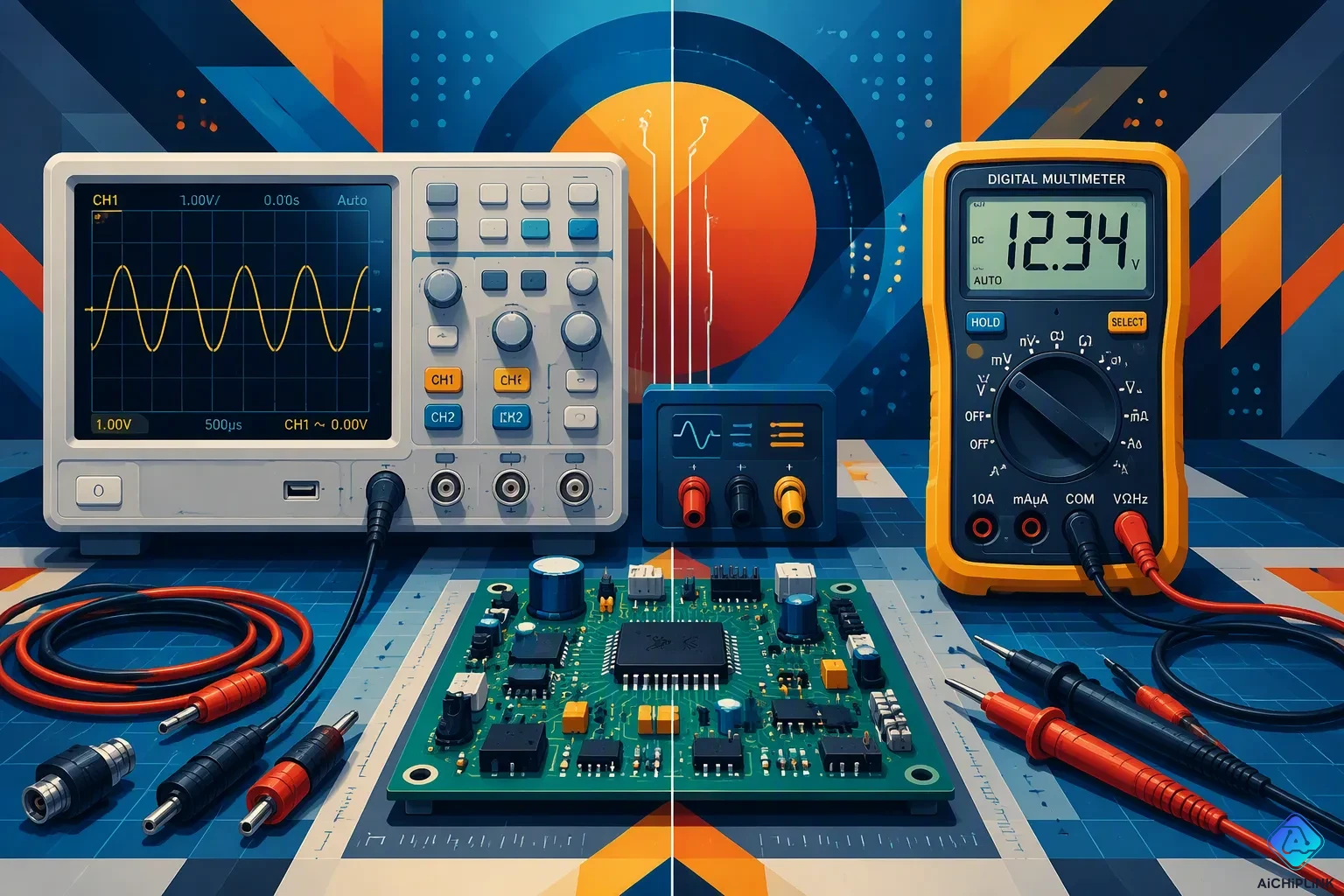
Electronic test and measurement is the process of using special tools to send signals to a device and record the responses. This practice checks performance, reliability, and quality. It forms the basis to verify correct operation and find faults in electronics.
Engineers use this practice in many industries. According to MarketsandMarkets, the world market for these tools was worth $48.65 billion in 2025. This number shows how big electronic testing and measurement is around the world. One test can show if a circuit works as planned or breaks under pressure. Each measurement helps with quality control at every step.
Key Takeaways
-
Electronic test and measurement checks how well a device works, finds problems, and makes sure it is reliable.
-
A digital multimeter checks voltage, current, and resistance for quick, basic tests.
-
An oscilloscope shows the shape of a signal over time. It reveals noise and glitches.
-
A spectrum analyzer shows signal strength at different frequencies to find interference.
-
Testing often saves money. It finds problems early and makes sure you follow the rules.
Fundamentals of Electronic Test and Measurement
Defining Electronic Test and Measurement
Electronic testing and measurement is a step-by-step process. An engineer sends a known signal into a device under test (DUT) and then reads the response. The DUT could be a single resistor, a circuit board, or a whole automotive control unit. The instrument checks if the response matches what it should be. If it matches, the device works correctly. If it doesn't, there is a problem.
This definition covers more than just one action. The process includes making a signal, capturing it, analyzing it, and reporting the results. Each step follows the one before it. A signal generator might create a sine wave. An oscilloscope then records the waveform that comes back. Software then compares the recorded shape to a reference. The full chain makes up one measurement cycle.
Engineers repeat this cycle under many different conditions. They change voltage, temperature, and timing. They look for changes in how the DUT responds. This repetition changes one reading into a trustworthy view of how the device acts.
Why It Matters for Quality
The main goal of this field is three things: check performance, find faults, and make sure the device is reliable. Checking performance shows that a device meets its design goals. Finding faults discovers the main cause when a device fails. Checking reliability makes sure the device continues to work over time.
Finding faults covers many types of part failures. A simple test can show the most common issues.
| Component | Common fault detected |
|---|---|
| Resistor | Open circuit or resistance drift |
| Capacitor | Short circuit, open circuit, or significant capacitance change |
| Diode | Short circuit or open circuit failure |
| Transistor | Burnt out or stuck in conducting/non-conducting state |
| IC | Internal circuitry failure, often causing no function |
| Fuse | Open circuit due to overload |
| Relay | Contacts failing to open or close properly |
| Connector | Loose, corroded, or broken connections |
Several main causes lead to these failures. Overheating causes heat stress that hurts semiconductors, resistors, and capacitors. Electrical overload forces too much current through a part and damages fuses, resistors, and integrated circuits. Aging and wear break down capacitors, connectors, and switches over time. Moisture and corrosion rust the traces on circuit boards and part pins. Physical damage from mechanical stress hurts fragile parts like SMD diodes, transistors, and ICs. Bad solder joints cause faults that come and go or total failures.
Quality relies on finding these problems early. A maker that skips this step sends out bad parts. A repair team that skips it puts broken equipment back into use. Both results hurt trust and increase costs.
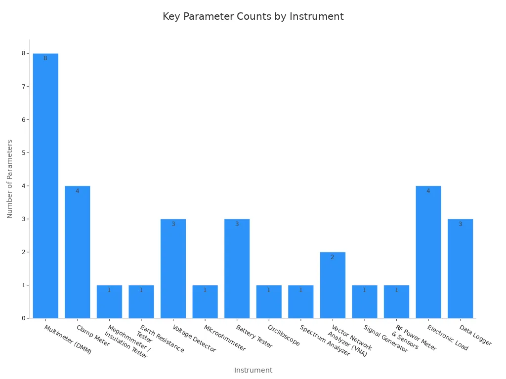
The chart above shows how many measurements each common tool can make. A digital multimeter measures voltage, current, resistance, and more. An oscilloscope records voltage changes over time. A spectrum analyzer shows signal strength across different frequencies. Each tool helps a test program do more.
A strong quality program uses several tools together. One tool by itself cannot find every type of failure. Together, they give engineers the complete view they need.
Key Electronic Test Equipment Explained
Core Instruments: Multimeters and Oscilloscopes
A digital multimeter is the basic tool in any electronics lab. It measures voltage, current, and resistance using a simple pair of probes. Technicians grab a digital multimeter first because it answers basic questions quickly. Is this outlet live? Does this resistor match its label? A digital multimeter gives a direct reading without complex setup.
Buyers see a wide price range when picking a digital multimeter. The table below shows typical costs for professional-grade units.
| Meter Category | Average Price | High-End Price | Notes |
|---|---|---|---|
| True RMS / specialty meters | $100–$250 | $350 | AC analysis, capacitance, frequency, logging |
| Fluke-grade / high-end meters | $200–$500 | $1,000 | Professional safety ratings, rugged builds, premium features |
| Standard multimeter unit | $40–$60 | $200–$300 | Basic to advanced; true RMS and autoranging affect price |
A digital multimeter works well for quick checks. An oscilloscope goes further by drawing a picture of a signal over time. The oscilloscope shows shape, amplitude, and timing on a screen. Engineers use an oscilloscope to find noise, distortion, or glitches that a meter cannot reveal. A digital multimeter reports one number. An oscilloscope shows the full waveform. Both tools belong on the same bench. An oscilloscope turns an invisible electrical signal into a visible trace. That trace tells a story about circuit behavior.
Advanced Tools: Spectrum Analyzers and More
A spectrum analyzer goes beyond the time domain. It displays signal strength across a range of frequencies. This view reveals harmonics, interference, and unwanted emissions. Handheld spectrum analyzers bring this power into the field. The SignalHawk SH-60S covers 9 kHz to 6 GHz. The SignalHawk SH-75S extends that coverage to 9 kHz to 7.5 GHz. The RF Explorer 6G, a handheld digital spectrum analyzer, specifies a frequency band of 4850–6100 MHz. These ranges let engineers check wireless devices, broadcast gear, and radar systems on site.
Parametric measurement solutions handle precise characterization. These instruments measure resistance, voltage, and current with high accuracy. They support semiconductor testing and component qualification. A parametric analyzer verifies that a transistor meets its datasheet limits. This level of precision matters for research and production.
The right electronic test equipment depends on the job. A digital multimeter covers basic electrical checks. An oscilloscope reveals signal behavior over time. A spectrum analyzer exposes the frequency domain. A parametric solution delivers exact component data. Each tool answers a different question. Together, they form a complete measurement toolkit. No single instrument handles every task. A skilled engineer selects the right tool for each test. That choice determines the quality of the result.
Measurement Types in Electronic Testing and Measurement
DC and AC vs. Analog and Digital
Engineers group signals by how they act over time. A DC signal stays at one steady value, like the 5 volts from a phone charger. An AC signal moves back and forth, like the 60 Hz power from a wall outlet. A digital multimeter measures both types. It gives one number for DC voltage or an RMS value for AC. This basic split shapes every test plan.
Analog and digital signals add another layer. An analog signal changes smoothly and can take any value within a range. A digital signal jumps between two levels, usually called high and low. A digital multimeter handles both, but the right mode matters. A technician who picks the wrong setting gets a reading that misleads. The signal type decides the tool and the setup.
Time-Domain Versus Frequency-Domain Analysis
Time-domain analysis shows how a signal changes from moment to moment. An oscilloscope works best here. It draws voltage on the vertical axis and time on the horizontal axis. This view shows rise time, overshoot, and glitches. A digital multimeter cannot show these details because it reports only one value. An oscilloscope turns an invisible event into a visible trace.
Frequency-domain analysis shows how much energy a signal carries at each frequency. A spectrum analyzer handles this task. It reveals harmonics, noise, and interference that a time-domain view hides. A clean sine wave in the time domain may show unwanted spikes in the frequency domain. Each domain answers a different question.
Different tests need different approaches. A power supply check may need only a DC measurement. A wireless transmitter requires frequency-domain analysis. An audio circuit often needs both. The signal characteristics guide the engineer's choice. No single method covers every case. A skilled technician matches the approach to the problem at hand.
Real-World Applications of Electronic Testing and Measurement
Design Verification and Production Testing
Engineers depend on electronic testing and measurement when they verify a design. They build a prototype and send signals through it. The instruments catch the response and compare it to the design goals. A spectrum analyzer checks a wireless radio for unwanted emissions. An oscilloscope confirms that a timing circuit hits its target. This step finds problems before mass production starts. A flaw caught at this stage costs much less to fix than one found in the field.
Production testing takes over once a design passes verification. Every unit on the line has to meet the same standard. Automated systems run the same test sequence on each board. The role of automation grows here because speed and repeatability matter. Manual probing cannot keep up with a high-volume line. Automated fixtures apply signals, read responses, and sort good units from bad ones. This approach takes human error out of the process.
Some organizations can even cut the time spent testing by 80 percent.
That gain frees engineers to focus on harder problems. Electronics manufacturing, telecommunications, and automotive plants all depend on this flow. A single faulty control unit in a car can threaten safety. A weak transceiver in a cell tower can drop calls. Production tests guard against both outcomes.
Maintenance, Troubleshooting, and Compliance
Field technicians use the same tools for maintenance and troubleshooting. A digital multimeter checks a power supply for the correct voltage. An oscilloscope traces a signal through a faulty circuit board. The technician compares the measurement to a known good value. This comparison points to the failed component. Repair teams then replace the part and verify the fix. Regular tests extend equipment life and reduce downtime.
Compliance testing proves that a product meets legal and safety standards. Governments require limits on electromagnetic emissions and electrical safety. A spectrum analyzer measures radiated energy against those limits. A parametric analyzer confirms that components stay within their rated values. Automotive suppliers must meet strict rules for electronic control units. Telecommunications gear must avoid interfering with other signals. Each phase of a product lifecycle relies on electronic testing and measurement. Design, production, maintenance, and compliance all rest on the same foundation.
Electronic test and measurement gives engineers a step-by-step way to check device behavior. An oscilloscope shows time-domain waveforms. A digital multimeter gives exact voltage or current readings. The oscilloscope also shows signal quality during production tests. These tools support all major measurement types, from simple DC checks to complex frequency analysis. Analysts say the global market for this equipment will grow 5.7% to 6% each year until 2030. This field covers design checks, factory testing, and field repairs. Each measurement method answers a question about circuit health. Engineers can learn about these tools to work better and fix problems confidently.

Written by Jack Elliott from AIChipLink.
AIChipLink, one of the fastest-growing global independent electronic components distributors in the world, offers millions of products from thousands of manufacturers, and many of our in-stock parts is available to ship same day.
We mainly source and distribute integrated circuit (IC) products of brands such as Broadcom, Microchip, Texas Instruments, Infineon, NXP, Analog Devices, Qualcomm, Intel, etc., which are widely used in communication & network, telecom, industrial control, new energy and automotive electronics.
Empowered by AI, Linked to the Future. Get started on AIChipLink and submit your RFQ online today!
Frequently Asked Questions
What does electronic test and measurement actually do?
An engineer sends a known signal into a device under test and reads the response. The instrument checks if that response matches the expected value. This cycle checks performance, finds faults, and confirms reliability. This process covers a single resistor, a circuit board, or a full automotive control unit.
Which instrument should a technician reach for first?
A digital multimeter answers basic questions about voltage, current, and resistance with a pair of probes. An oscilloscope goes further and draws the signal shape over time. A spectrum analyzer reveals signal strength across frequencies. The job decides the tool, and no single instrument handles every task.
Why do engineers separate time-domain and frequency-domain analysis?
Time-domain analysis shows how voltage changes moment to moment, and an oscilloscope gives this view. Frequency-domain analysis shows energy at each frequency, and a spectrum analyzer covers that ground. A clean sine wave in one domain may hide unwanted spikes in the other. Each domain answers a different question.
How fast is the market for this equipment growing?
Analysts expect the global market for this equipment to grow 5.7% to 6% each year until 2030. The market was worth $48.65 billion in 2025. That growth shows steady demand across electronics manufacturing, telecommunications, and automotive production. Each industry uses the same measurement foundation.