RF Mixer Fundamentals: Types, Uses, and Selection
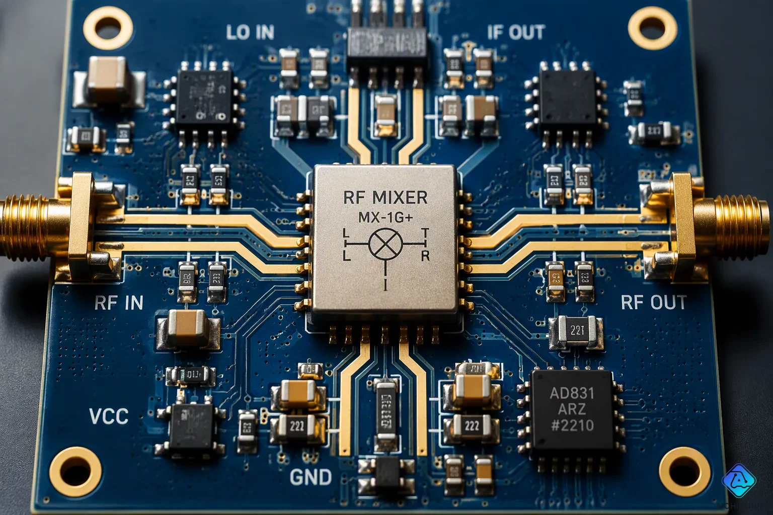
What is an RF mixer, and why is it so important in modern wireless communication? An RF mixer is a nonlinear circuit that changes frequencies. It takes two input signals and creates both their sum and their difference. This device has three ports: local oscillator (LO), RF, and IF. You use mixers for two main jobs. Up-conversion moves baseband signals up for transmitters. Down-conversion moves RF signals down to a lower IF for receivers. This guide explains the different types of RF mixers. You will learn key performance metrics. You will also get a practical way to pick the right mixer for your needs. Knowing these basics helps you make smarter design choices for your specific uses.
Key Takeaways
-
RF mixers alter signal frequencies by making sum and difference outputs.
-
Pick the mixer type based on what you need: unbalanced for low cost, balanced for better isolation.
-
Active mixers boost the signal, while passive mixers keep noise lower.
-
Key specs to compare include conversion loss, noise figure, and linearity.
-
Pick a mixer that fits your system's frequency, impedance, and power levels.
RF Mixer Basics: Frequency Conversion
Every rf mixer changes one frequency to another. You send the LO signal into one port. The rf signal goes into another port. The mixer makes new frequencies at its output. That output port is the intermediate frequency (if) port. This works because the mixer acts in a nonlinear way. It multiplies the two input signals together.
The Three-Port Device and Nonlinear Operation
A mixer has three ports. You connect the LO to one port. The rf goes to another port. The if port gives you the result. The device uses a part that is not linear. This part can be a diode or a transistor. When you put in two sine waves, the output has more than just the original frequencies.
When you multiply two input signals, v1 = sin(2πf1t) and v2 = sin(2πf2t), you can expand it using this identity: v1v2 = ½cos[2π(f1−f2)t] − ½cos[2π(f1+f2)t]. This shows that multiplication makes only two new parts. One is at the difference frequency (f1−f2). The other is at the sum frequency (f1+f2).
A diode’s nonlinear current-voltage link creates these new frequencies. The squared term in its power series gives the sum and difference terms. This is how frequency conversion works.
Nonlinearity also makes unwanted parts. The cubic term in the power series creates intermodulation frequencies. These include 2×f2−f1 and 2×f1−f2. When the two input frequencies are close, these new frequencies land near the original ones. They become hard to filter out. This is a key problem.
-
First-order products hold only the original frequencies.
-
Second-order products contain the sum and difference frequencies.
-
Third-order products cause the most trouble from intermodulation.
Up-Conversion vs. Down-Conversion in Systems
You use a mixer for two main jobs. In a transmitter, you do upconversion. You take a baseband signal and move it up to a higher rf. This shift lets the signal travel through the air. The LO gives the carrier. The mixer outputs the sum frequency.
In a receiver, you do downconversion. You take the incoming rf and move it down to a lower if. This shift makes the process easier. The mixer outputs the difference frequency. Both upconversion and downconversion use the same nonlinear mixing process. They just pick different output ports.
These two operations are basic to modern communication systems. You find them in radios, cell phones, and radar. Knowing the difference helps you pick the right mixer for your tasks. Mastering frequency conversion is key for any engineer.
Common Types of RF Mixers
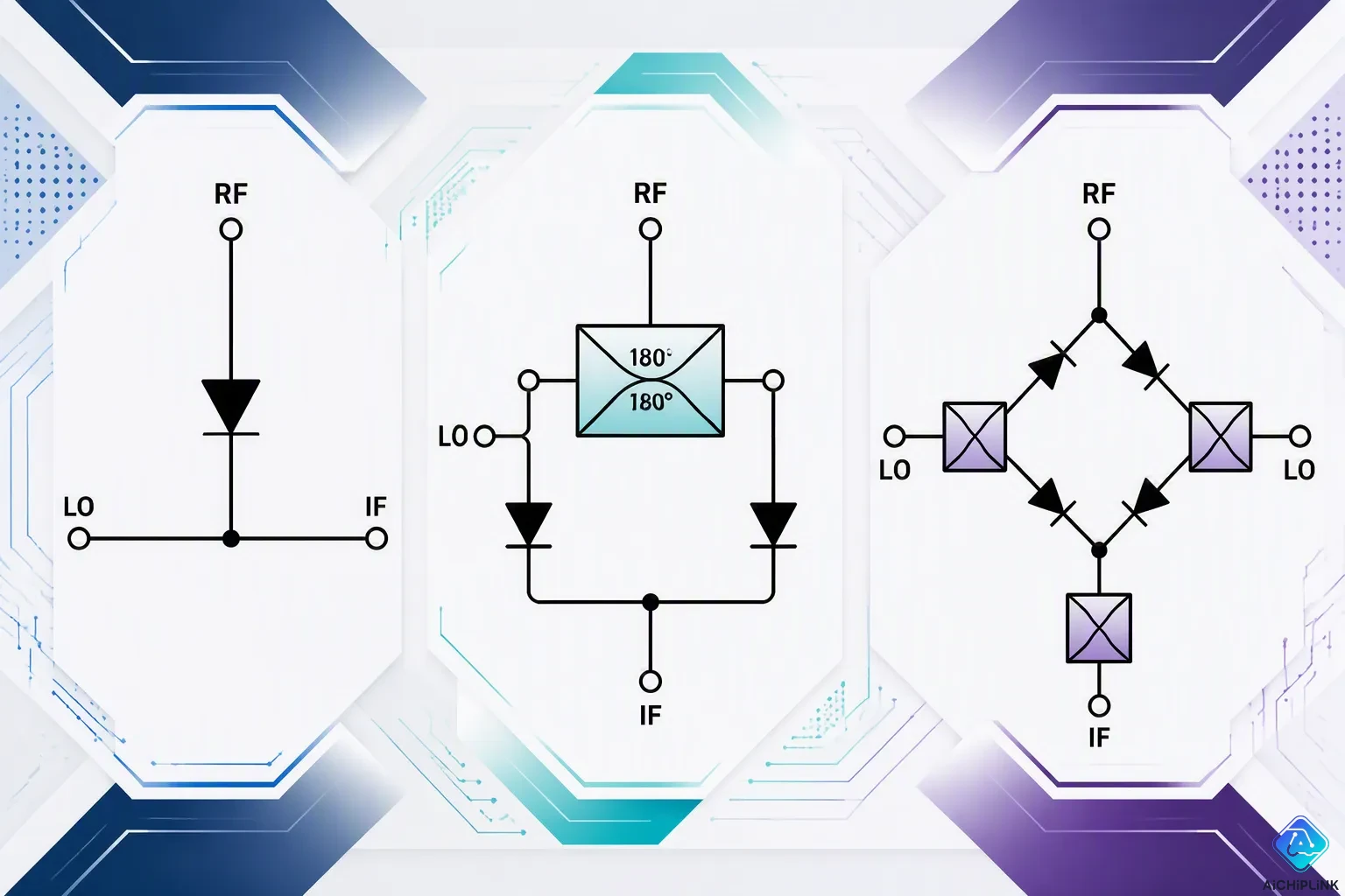
You have many options when picking a mixer for your circuit. Each design trades off complexity against performance. Knowing the main types of rf mixers helps you choose the right part for your system. The three basic groups are unbalanced, single-balanced, and double-balanced designs. Each one deals with port isolation and unwanted signals in its own way.
Unbalanced, Single-Balanced, and Double-Balanced Topologies
The easiest design uses one diode. This unbalanced mixer has no isolation between ports. The RF, LO, and IF signals all show up at the output together. You need a narrowband filter to get rid of the extra content. This method works for low-cost uses where performance needs stay low.
A single-balanced mixer adds a 180° hybrid coupler, also called a balun, with two diodes. This setup isolates either the RF or the LO port, but not both. You still need filtering for the port that is not isolated. The balanced structure cuts AM noise from the LO, which makes your signal better.
A double balanced mixer goes further. It uses four diodes in a ring plus two baluns. This design gives natural isolation of both RF and LO ports. The IF port sends out only the mixing products you want. You need no extra filtering at the IF output. The diode ring switches based on the LO polarity. On positive half-cycles, diodes D1 and D2 conduct. On negative half-cycles, D3 and D4 take over. The LO signal switches the RF signal at the LO frequency, making the sum and difference frequencies at the IF port.
| Feature | Unbalanced (Single Diode) | Single Balanced | Double Balanced |
|---|---|---|---|
| Circuit parts | 1 diode | 2 diodes + 180° hybrid coupler | 4 diodes in ring + 2 baluns |
| Port isolation | No isolation | Isolates either RF or LO | Isolates both RF and LO |
| Output filtering | Needs narrowband IF filter | Needs filtering for non-isolated port | No filtering needed at IF port |
| LO power need | Lowest | Least among balanced types | Higher than single-balanced |
| Linearity | Not given | Less linear | More linear |
| Spurious outputs | No rejection | Reduced intermodulation products | Less spurs than single-balanced |
| Bandwidth | Narrow | Narrow | Broadband |
The double balanced mixer gives the best performance among these types. It blocks both input signals at the IF port. This happens because equal LO voltages appear at the center taps of both transformers. A balanced RF null also exists at the IF port. You get better rejection of spurious products and higher linearity. The trade-off is higher LO drive levels and the cost of two baluns. Taking the IF from the RF balun can give you about 20 dB more LO rejection than normal setups.
Active vs. Passive Mixers and IQ Mixers
You also pick between active mixers and passive mixers. Passive mixers use diodes as the nonlinear switching part. They need no DC bias. These parts have low noise figures but need higher LO power to work right. Active mixers use transistors instead. They give conversion gain, which means the output signal is stronger than the input. This gain comes with a higher noise figure.
| Mixer Type | Parameter | Typical Value |
|---|---|---|
| Passive | Conversion Loss | 5–8 dB |
| Passive | Noise Figure | 5–10 dB |
| Active | Conversion Gain | 5–15 dB |
| Active | Noise Figure | 10–15 dB |
The table shows the main difference. Passive mixers lose signal strength through conversion loss. Active mixers boost the signal through conversion gain. Your choice depends on whether your system needs gain or low noise. A receiver front-end might pick a passive mixer for its low noise. A transmitter chain might use an active mixer to raise signal levels.
An IQ mixer solves a different issue. This type of rf mixer handles image rejection through phase cancellation. The design splits the RF signal into two equal in-phase paths. The LO splits with a 90° phase difference. Two separate mixers process these paths. The resulting IF outputs sit 90° apart in phase. An external 90° hybrid combines them.
The image rejection process works through careful phase relationships:
-
The desired RF signal path makes two IF outputs that are 90° out of phase. The external hybrid combines these constructively at Port 2, giving you the full IF output.
-
The image signal path makes IF signals with a -90° phase difference. This opposite phase causes cancellation at Port 2.
-
The image signal combines at Port 1 instead. You end Port 1 with a 50Ω load, which absorbs the unwanted image.
Real-world flaws affect the performance of an iq mixer. Phase unbalance of 10° plus amplitude unbalance of 1 dB gives 20 dB of image rejection. These values are easy to reach in real designs. The SMIQ-65H-D+ mixer gets about 20 dB of image rejection across most of its band. It does better than 25 dB over the 40 to 52 GHz range. This shows that real designs give good image rejection even with part imbalances.
Each mixer type has a purpose. Unbalanced mixers fit simple, low-cost designs. Balanced mixers give better isolation and spurious rejection. Active mixers give you gain. Passive mixers keep noise low. IQ mixers reject images. Your application decides which type works best. Think about your frequency plan, available LO power, and system noise budget when you choose.
RF Mixer Performance Metrics
You need clear numbers to check any RF mixer's quality. These numbers show how well the part changes frequencies and how much extra noise it adds. Four key things matter most: conversion loss, noise figure, linearity, and port isolation. Each one affects your system's overall performance. Learning these performance factors helps you compare parts in a smart way.
Conversion Loss, Noise Figure, and Gain
Conversion loss measures the power drop from the RF input to the IF output. You write this value in dB. A lower number means better performance. Passive mixers usually have 5–8 dB of conversion loss. Active mixers give you conversion gain instead. They boost the signal by 5–15 dB. This gain performance changes how you design your system.
You can measure conversion loss with a vector network analyzer using Scalar Mixer Calibration. This method needs frequency-offset mode. You can run a full SOLT calibration on both frequency ranges for better accuracy. Or you can use a single cycle with interpolation for speed. A spectrum analyzer with a tracking generator gives another option. The tracking source sweeps across the LO frequency. The analyzer then measures the lower sideband at the output. Both methods give reliable results.
Noise figure tells you how much extra noise the mixer adds. Passive mixers show noise figures of 5–10 dB. Active mixers usually range from 10–15 dB. Your choice depends on your receiver's noise budget. A low-noise front end might pick passive mixers even with their conversion loss. This noise performance directly affects your receiver's sensitivity.
Linearity Metrics (IP3, P1dB) and Port Isolation
Linearity shows how well a mixer handles strong signals without making distortion. The 1 dB compression point (P1dB) is where the output power drops 1 dB below the perfect linear response. The third-order intercept point (IP3) predicts how intermodulation will behave. You can estimate IIP3 from P1dB using this formula: IIP3 ≈ IP1dB + 9.6 dB. Typical mixer IP1dB values range from -5 to +15 dBm. That gives IIP3 values from +4.6 to +24.6 dBm. High-performance base station mixers sit at the upper end of this range. Their linearity handles strong cell signals well.
Port isolation stops signal from leaking between ports. LO-to-RF isolation is the most important type. You measure it by ending the IF port with a 50-ohm load. Then you apply LO drive power and measure the LO power at the RF port. The difference gives you the isolation value. A double balanced mixer naturally gives good isolation. Mini-Circuits double-balanced mixers get 30 dB of isolation at their highest working frequency. This mixer performance makes the design useful for tough tasks in communication systems. The overall quality of your mixer choice depends on all these factors working together.
How to Select an RF Mixer: A Practical Guide
Picking the right rf mixer for your system takes a clear plan. You can't just grab the cheapest part or the one with the best numbers on paper. You need a step-by-step method that fits what your system really needs. This guide shows you that process. You will learn how to check each choice against your own needs.
Matching Frequency, Impedance, and Power Levels
Start by setting your frequency range. Your mixer must cover the bands you will use. Write down the exact frequencies for your LO, RF, and IF ports. Then make sure the mixer supports all three ranges at the same time. Many parts claim wide bandwidths, but you must check the overlap across every port.
Next, look at impedance matching. Most mixers expect 50-ohm systems. You need to make sure your source and load impedances match this value. A mismatch causes reflections. Those reflections lower the signal power and create standing waves. You can add matching networks, but they take up board space and add loss.
Now think about LO drive power. Passive mixers need higher LO levels, often around +7 to +13 dBm. Active mixers need less drive but require DC bias. Check what your local oscillator can provide. If your LO output is weak, you may need an amplifier or a different mixer type.
For a satellite communication receiver, the selection criteria follow a clear order of importance. The table below shows what matters most.
| Selection Criterion | Reason for Satellite Communication Receiver |
|---|---|
| Low Noise Figure | Key for picking up weak signals from satellites |
| Good Linearity | Cuts intermodulation distortion that can ruin received signals |
| Moderate Power Handling | Needed to support uplink transmission paths |
| Broadband Operation | Allows support for multiple satellite frequency bands |
The full selection checklist for this use includes nine steps. First, confirm the frequency range covers your satellite bands. Second, reduce conversion loss to keep signal strength. Third, check linearity for intermodulation protection. Fourth, treat noise figure as a top priority for weak signal reception. Fifth, verify port-to-port isolation stops LO leakage into RF or IF paths. Sixth, match LO power needs to your available oscillator output. Seventh, confirm impedance matching for maximum power transfer. Eighth, ensure moderate power handling for uplink paths. Ninth, pick packaging that fits your physical limits.
Balancing Cost, Size, and Performance Trade-Offs
Once you set the technical needs, you must weigh practical factors. The mixer topology you choose affects cost and size directly. A simple unbalanced design uses one diode and costs little. A double balanced mixer uses four diodes plus two baluns. It costs more but gives better isolation and spurious rejection. An iq mixer adds another layer of complexity for image rejection.
Your choice between active mixers and passive mixers also depends on your system budget. Active mixers provide conversion gain, which can save you an amplifier stage downstream. However, they add higher noise figure. Passive mixers lose signal through conversion loss but keep noise low. For a receiver front end, passive mixers often win because sensitivity matters most. For a transmitter chain, active mixers help boost signal levels.
Think about the application environment too. High-volume commercial designs demand low cost and small packages. You might accept moderate performance to hit a price target. Military and space applications prioritize reliability and performance over cost. They can justify larger packages and higher prices. The same mixer types appear in both worlds, but the selection criteria shift.
Every performance metric you learned earlier feeds into this decision. Conversion loss affects your gain budget. Noise figure affects your receiver sensitivity. Linearity determines how well you handle strong nearby signals. Port isolation prevents unwanted leakage. You must balance all these factors against cost and size limits. No single mixer excels in every category. Your job is to find the best trade-off for your specific use case.
The selection process becomes easier when you follow a structured method. Define your frequencies first. Choose active or passive based on gain needs. Evaluate linearity and noise figure for your application. Then compare cost and size across viable options. This approach works for any communications system, from simple radios to complex satellite links.
RF mixers do a key job in every wireless communication system. They change signal frequencies. The type you pick depends on what you need it for. You have to weigh important specs like conversion loss, noise figure, and linearity. Knowing each design—unbalanced, balanced mixer, active mixers, passive mixers, and iq mixer—helps you use this selection guide well. Each type handles the if signal in its own way for its job.
New trends point toward built-in mixers inside MMICs for 5G and radar. These improvements make rf designs simpler while working better. Use what you have learned on your next rf communications project. Learn these basics well to make sure your choices are solid.

Written by Jack Elliott from AIChipLink.
AIChipLink, one of the fastest-growing global independent electronic components distributors in the world, offers millions of products from thousands of manufacturers, and many of our in-stock parts is available to ship same day.
We mainly source and distribute integrated circuit (IC) products of brands such as Broadcom, Microchip, Texas Instruments, Infineon, NXP, Analog Devices, Qualcomm, Intel, etc., which are widely used in communication & network, telecom, industrial control, new energy and automotive electronics.
Empowered by AI, Linked to the Future. Get started on AIChipLink and submit your RFQ online today!
Frequently Asked Questions
What is the difference between active mixers and passive mixers?
Active mixers use transistors to provide conversion gain. They make the signal stronger but also add more noise. Passive mixers use diodes and cause conversion loss. They need more LO power but keep the noise figure lower.
How does conversion loss affect your system performance?
Conversion loss lowers the signal power from the RF input to the IF output. A passive mixer with 5–8 dB of loss will need more gain later in the receiver chain. This changes your overall noise budget and design.
What types of rf mixers work best for communications applications?
For communications systems, a double balanced mixer is the best choice. It gives good isolation between ports and blocks unwanted signals. This makes filtering easier and improves signal quality.
Why do you need a balanced mixer in your design?
A balanced mixer provides better port isolation than an unbalanced design. It stops LO leakage into the RF path. This guide says double balanced mixers give about 30 dB of isolation for cleaner signal handling.