What is an Inductive Sensor?
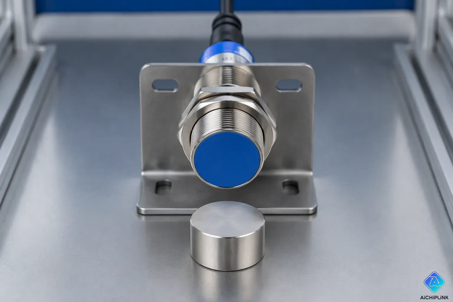
An inductive sensor is a non-contact electronic device that detects ferrous metal targets. You mainly use it in factory automation for position, presence, and speed sensing. The technology works by using an electromagnetic field, which we will explain in detail soon.
The market for inductive sensors keeps growing at a steady rate. Industry projections show a compound annual growth rate of about 5.5% from 2024 to 2030. This growth happens because factories are investing more in automated systems.
You will learn how an inductive sensor works, its main types, and how to pick the right one for your job. Knowing these basics helps you choose reliable sensing solutions for your automation projects.
Key Takeaways
-
Inductive sensors detect metal without touching it, using electromagnetic fields.
-
The distance a sensor can detect changes based on the material it's sensing. To get accurate results, you must use correction factors.
-
Use shielded sensors when you need to mount them flush. Pick unshielded sensors when you want a longer range.
-
Match NPN or PNP output to your PLC input for correct wiring.
-
Inductive sensors can handle dust, oil, and shaking, so they work great in tough places.
How Inductive Sensors Work
To understand inductive sensors, start with the oscillator circuit inside the device. This circuit powers a coil that creates a high-frequency electromagnetic field at the sensor face. That field spreads outward into the space around it, forming an invisible detection zone. When no metal target enters this zone, the oscillator runs at full strength. The sensor's monitoring circuitry keeps watching this signal level.
The Electromagnetic Field and Target Interaction
When a ferrous metal object enters the electromagnetic field, a fast chain of events begins. The changing magnetic flux goes into the target material and creates circulating electrical currents inside it. Engineers call these eddy currents. These currents make their own opposing magnetic field that pushes back against the sensor's original field. This push pulls energy from the oscillator circuit and releases it as heat inside the target material.
That energy loss directly lowers the amplitude of the oscillator's signal. The sensor's monitoring circuitry notices this drop and triggers the output when it goes below a set point. This set point usually sits at 50–70% of the normal amplitude. The whole process happens in milliseconds, so it allows for high-speed detection in industrial settings.
The link between target material properties and sensing performance follows a clear pattern. The depth that eddy currents reach depends on the material's resistivity and the frequency of the alternating field. Higher conductivity creates stronger eddy currents, which gives a longer sensing range. This link forms the base of inductive sensor operation.
Sensing Range and Correction Factors
Every inductive sensor has a rated sensing range, called Sn. Manufacturers set this rating using a standard target made of mild steel, specifically Fe 37 steel. This standard gives you a steady baseline for comparing different sensors. But real-world targets rarely match this standard material exactly.
Non-ferromagnetic metals with lower conductivity give only 30–70% of the sensing distance you get with Fe 37 steel. Low-conductivity metals like lead or tin may drop sensing distance to below 30% of the rated value. For example, the standard correction factor for aluminum when using an inductive sensor made for steel is 0.4 Sn. That means the effective sensing distance falls to 40% of the rated distance on steel. Brass follows a similar pattern with a correction factor of 0.5 Sn.
A bigger metal target does not increase the sensing range, but a smaller object greatly reduces the sensing range. The same applies to the thickness of the metal target – objects thicker than 1 mm do not affect the sensing range, but thinner objects do.
You must consider these correction factors when picking an inductive sensor for your job. If you need to detect aluminum parts at a distance of 10 mm, you would need a sensor rated for 25 mm on steel. This calculation ensures reliable detection without false triggers or missed targets. The correction factor method gives you a practical way to use inductive sensors with different materials. Understanding how inductive sensors work with target materials helps you make smart choices for your automation projects. Inductive sensors give predictable performance when you apply these correction factors correctly. Each inductive sensor type reacts differently to various metals, so you should always check the correction factor for your specific target material. Inductive sensors stay reliable choices for metal detection when you understand these basic principles.
Inductive Sensor Types and Components
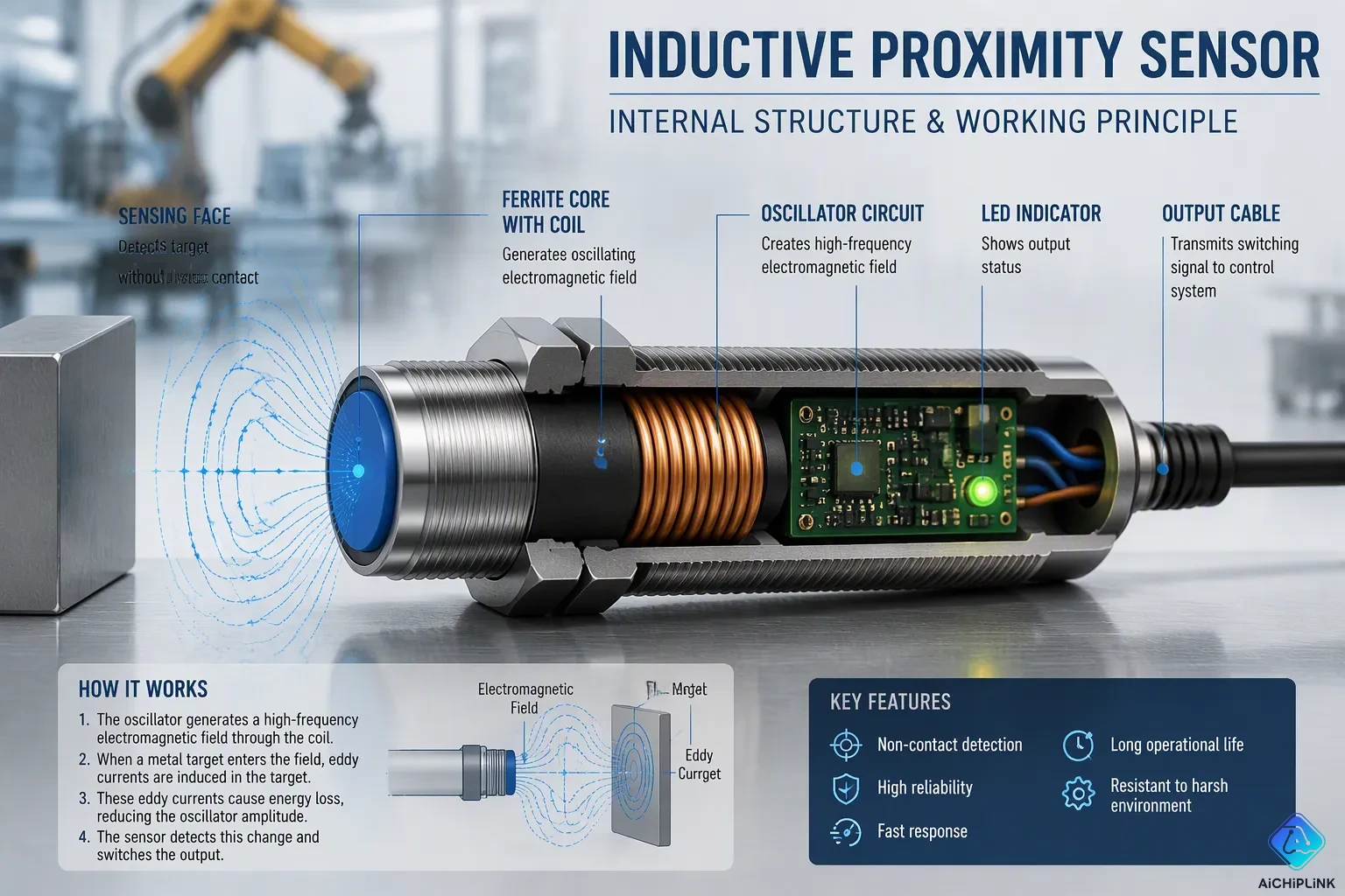
You will see that inductive sensors look similar in design, even from different brands. The body is usually round or rectangular. You mount this body in a machine or fixture where you need detection. The sensing face is at one end, and you point it toward the metal target. An LED on the body shows you status. The output cable or connector sends the signal to your control system.
Core Components of an Inductive Proximity Sensor
Inside the housing, you will find the key parts that make detection possible. The oscillator circuit creates the high-frequency signal. The coil, wrapped around a ferrite core, makes the electromagnetic field. The ferrite core helps the coil by holding a magnetic material that boosts the field. This boost improves the sensor's efficiency and sensitivity because the core focuses and guides the field lines. That focusing improves detection accuracy and extends the detection range.
The housing material matters for durability in tough conditions. You have several choices based on your use:
| Body Material | Application Context | Key Property |
|---|---|---|
| 303 or 316 Stainless Steel | General harsh environments, high-pressure washdown, high-temperature, impact-prone areas | Single-piece gun-drilled housing; provides physical protection; withstands high-pressure water (IP69K) and high temperatures |
| PTFE (Teflon®) | Welding environments, high-temperature applications | Slag-resistant body coating; high-temperature-rated face material; chemical resistance at high temperatures |
| Ceramic-based coatings | Welding environments (sensor face) | Protects and extends the life of the sensor face against weld slag and impact |
The indicator LED gives you quick status updates. You can check the sensor's condition from a distance without extra tools:
| LED Function | Visual Feedback Method | Operator Benefit |
|---|---|---|
| Power status indication | Steady illumination when powered | Immediate confirmation that the sensor is energized |
| Detection event indication | Illumination change upon object detection | Real-time awareness of sensing activity |
| Fault condition indication | Distinct color or blinking pattern | Quick identification of anomalies for faster troubleshooting |
Shielded vs. Unshielded and Output Configurations
You will see two main mounting styles when picking an inductive proximity sensor. Shielded sensors have a metal ring around the sensing face. This ring keeps the electromagnetic field from spreading sideways. You can place a shielded sensor flush into a metal surface without losing sensing range. Unshielded sensors have no such ring. Their field spreads further out and to the sides. You cannot embed them in metal without a clearance zone.
| Feature | Shielded (Flush) | Unshielded (Non-Flush) |
|---|---|---|
| Embedding in metal | Can be embedded flush with metal surface without reducing sensing range | Cannot be embedded; requires a metal-free zone (typically ≥ 3x sensor diameter) |
| Sensing range | Shorter | Longer (1.5–2x shielded) |
| Lateral field radiation | Suppressed | Significant, causes false triggers near metal |
| Mounting requirement | Minimal/no metal-free zone | Must retain metal-free area in all directions |
Shielded sensors can be placed into a metal mounting fixture up to the point where the sensor's face is level with the surface, without reducing sensing range. However, unshielded sensors cannot be fully embedded because their longer sensing distance makes them sensitive to nearby metals. For unshielded sensors, you must keep a metal-free area around the sensor, equal to its diameter in every direction, with a depth clearance of two times the standard sensing distance. Not meeting these clearance needs leads to false detection or shorter sensing distances.
You also need to pick between AC and DC power types. AC sensors work with standard industrial power supplies. DC sensors run on low-voltage DC, usually 10–30V. The response time differs a lot between these types:
AC proximity sensors typically have 10-20ms response times, while DC sensors offer 0.1-1ms response.
For DC sensors, you will choose between NPN and PNP output setups. These terms describe how the output transistor switches. A PNP sensor sends positive voltage when triggered. An NPN sensor connects to ground when triggered. The wiring follows a standard 3-wire color code: Brown wire = +24V DC (positive supply), Blue wire = 0V DC (negative/ground), Black wire = output signal line.
For a PNP sensor, when triggered, the black wire sends +24V. You connect brown to positive, blue to negative, and black to a sinking PLC input. For an NPN sensor, when triggered, the black wire sends 0V. You connect brown to positive, blue to negative, and black to a sourcing PLC input. The load wiring also differs. For PNP, the load connects permanently between the output and 0V (negative supply). For NPN, the load connects between +24V (positive supply) and the output.
| Wiring Aspect | PNP Sensor (Sourcing) | NPN Sensor (Sinking) |
|---|---|---|
| Current flow direction | Sensor output → load → ground | Positive pole → load → sensor output |
| Voltage output when triggered | High-side switching (+24V) | Low-side switching (0V) |
| PLC input compatibility | Matches sinking PLC inputs | Matches sourcing PLC inputs |
| Load connection requirement | Load connected between sensor output and 0V | Load connected between +24V and sensor output |
Knowing these types of inductive sensors helps you pick the right device for your control system. The choice between shielded and unshielded affects your mounting design. The output type decides how you wire the sensor to your PLC. Each inductive sensor type serves a specific purpose, so you should check your electrical needs before buying. The different types of inductive sensors give you flexibility in designing your automation system. An inductive sensor with the correct output setup works smoothly with your existing controls. You will find that inductive sensors give reliable performance when you choose the right variant for your application.
Inductive Sensors: Key Advantages and Selection
Solid-State Reliability and Contaminant Resistance
An inductive sensor gives you great reliability because it has no moving parts. The solid-state design means nothing wears out. You can count on a long service life even in tough production settings. This durability makes inductive sensors a smart buy for nonstop operations.
The sealed build keeps the internal electronics safe from harsh conditions. You can put these devices in places with dust, dirt, oil, and coolant. The sensing face stays unaffected by non-metal contaminants that would stop other sensor types from working.
Inductive sensors are the workhorse of industrial automation. They are inexpensive, rugged, sealed, and largely immune to dust, oil, and coolant contamination.
You will see that inductive sensors beat photoelectric sensors in dirty environments. The table below shows the key differences:
| Condition | Inductive Sensor | Photoelectric Sensor |
|---|---|---|
| Dust | Immune; performance unaffected | Sensitive; can obstruct light beam and cause false readings |
| Oil/Grease | Immune; no performance degradation | Requires cleaning |
| Ambient Light | Unaffected | Can be interfered with by high ambient light |
| Vibration | Resistant | Through-beam types vulnerable to misalignment |
You also get strong resistance to mechanical stress. A stainless steel housing offers solid strength. These sensors handle shock up to 100g continuous and vibration up to 20g. They work reliably in temperatures from -40°C to 85°C without losing performance. For washdown jobs, you can pick models with IP68 and IP69K ratings. These sensors manage high-pressure cleaning with strong chemicals.
How to Choose the Right Sensor
You must look at several factors when picking an inductive sensor. Start with your target material. Steel gives you the full rated sensing range. Aluminum and brass cut that range down a lot. You need to use the correction factors we talked about earlier to find the real distance.
Next, figure out your required sensing distance. Measure the gap between the sensor face and the target in your setup. Add a safety margin of 20% to cover temperature drift and target changes. Then check your mounting space. A shielded sensor fits flush into metal. An unshielded sensor needs open space around its face.
Your environmental conditions matter as well. For food processing plants, choose a sensor with IP69K protection. For welding areas, pick a model with a PTFE or ceramic face coating. Think about the ambient temperature range. Standard inductive sensors work up to 70°C to 85°C. Specialized high-temperature versions handle 120°C or more.
Finally, match the electrical specs to your control system. You need the correct voltage, either AC or DC. You also need the right output type, either NPN or PNP. Check your PLC input setup before ordering. An inductive sensor with the wrong output will not talk to your controller.
Common Applications in Industrial Automation
You will find inductive sensors in many factory jobs. They can detect metal without touching it. This makes them very useful for reliable production lines. Let us look at the most common uses.
Detecting Part Presence and Cylinder Position
On a conveyor belt, an inductive sensor tells you when a metal part arrives at a certain spot. The sensor's coil makes a magnetic field. When a metal object enters this field, eddy currents form on its surface. These currents change the coil's impedance and alter the sensor's oscillation circuit. This triggers an electrical signal. Non-metal objects do not cause eddy currents, so they cause no impedance change. The sensor ignores them. This ability to tell metal from non-metal makes it perfect for part presence detection.
You also use an inductive sensor to confirm piston position on a pneumatic cylinder. The mounting process has three steps:
-
Put a split collar on the piston rod at the spot you want to sense.
-
Mount the sensor near the cylinder entrance so it can detect the collar.
-
Make sure the sensor's sensing field covers the collar's path. Use a shielded inductive prox with 8-10mm sensing range.
For PLC integration, a Mean Well DR-75-24 powers both the PLC and the sensor. The PNP inductive sensor outputs a positive signal when it detects a metal target. The PLC input is set up as a sinking (NPN) input. The sensor's positive signal completes the circuit. This lets the PLC read the metal target presence as position feedback. This setup turns the sensor into an inductive position sensor. You can use this inductive position sensor for any linear motion application.
Speed Monitoring and Motion System Feedback
You can measure rotational speed with an inductive sensor. Place it near a gear or a rotating shaft with a metal tooth. Each time the tooth passes the sensor face, it triggers a pulse. Count these pulses over time to calculate RPM. An inductive wheel sensor works well for this application. For tight spaces, an inductive slot sensor detects metal flags passing through a gap.
Inductive sensors also give feedback in motion control systems. They detect magnets, rotors, and stators without touching them. This non-contact operation stops wear and gives reliable feedback in servo and drive systems.
These inductive sensor applications show how useful these devices are. From simple part detection to complex motion feedback, inductive sensors give reliable performance. Inductive sensors form a basic part of modern factory automation.
You now understand why inductive sensors are essential tools in modern automation. These robust devices detect metal without touching it, using electromagnetic fields to deliver reliable performance in harsh environments. They withstand dust, oil, and vibration that would disable other sensor types.
Remember the correction factors. Aluminum reduces sensing range to 40% of rated distance, while brass gives you 50%. You must calculate these values before choosing your sensor.
Your selection depends on mounting space, target material, and electrical requirements. Choose shielded or unshielded based on your installation. Pick AC or DC, then match NPN or PNP outputs to your PLC.
Apply this knowledge to your next automation project. An inductive sensor will serve you reliably for years.

Written by Jack Elliott from AIChipLink.
AIChipLink, one of the fastest-growing global independent electronic components distributors in the world, offers millions of products from thousands of manufacturers, and many of our in-stock parts is available to ship same day.
We mainly source and distribute integrated circuit (IC) products of brands such as Broadcom, Microchip, Texas Instruments, Infineon, NXP, Analog Devices, Qualcomm, Intel, etc., which are widely used in communication & network, telecom, industrial control, new energy and automotive electronics.
Empowered by AI, Linked to the Future. Get started on AIChipLink and submit your RFQ online today!
Frequently Asked Questions
How do I verify the actual sensing range for my target material?
Take the rated sensing range (Sn) and multiply it by the correction factor for your metal. Steel has a factor of 1.0. Aluminum has 0.4. Brass has 0.5. If a sensor is rated at 10 mm on steel, it will only detect aluminum at 4 mm.
Can an inductive sensor detect non-metal objects?
No. Inductive sensors only pick up ferrous metals and other conductive materials. Plastic, wood, glass, and ceramics do not create eddy currents. When these materials enter the field, the oscillator keeps running at full strength. The sensor output never activates.
What happens if I mount an unshielded sensor too close to metal?
You will get false triggers or a shorter sensing distance. The metal mounting surface absorbs part of the electromagnetic field. You need a metal-free zone around the sensor face. Keep a gap equal to the sensor diameter in every direction. Also maintain a depth clearance of two times the standard sensing distance.
How do I choose between NPN and PNP output?
Check your PLC input type first. A PNP sensor sends +24V when triggered. It works with sinking PLC inputs. An NPN sensor sends 0V when triggered. It works with sourcing PLC inputs. Wiring the wrong output type means your controller never gets the signal. Verify your PLC specifications before ordering.