What is a SAW Sensor?
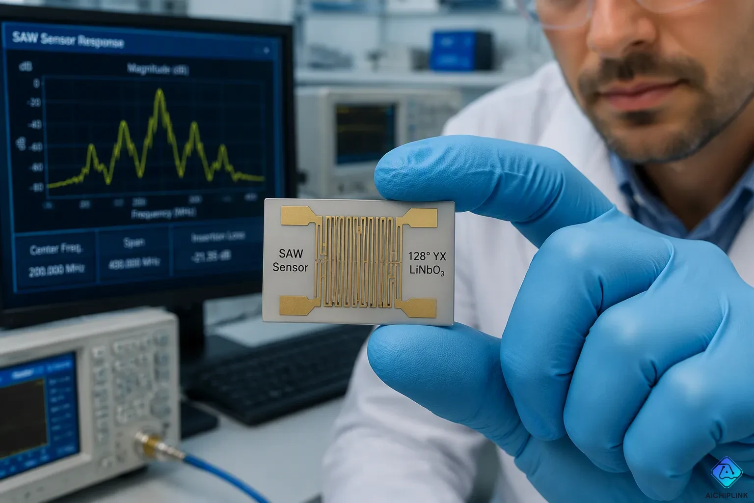
A SAW (Surface Acoustic Wave) sensor is a MEMS device that uses ultrasonic sound waves on a piezoelectric base. This surface wave sensor works without power or wires. The sound wave moves along the surface, and its speed changes with heat, pressure, or mass. Another surface wave gives a reference signal. This SAW sensor is very sensitive in a small size, and it can survive extreme places. These features make these sensors great for factory, car, airplane, and IoT uses. The SAW sensor then allows real-time tracking without a battery. It works in harsh places, and engineers often use it to measure torque.
Key Takeaways
-
SAW sensors don't need batteries or wires. A reader sends a signal. The sensor replies with data.
-
These sensors pick up very small changes in heat, pressure, or mass. They are very sensitive.
-
SAW sensors can handle very hot and very cold temperatures, as well as strong shaking. They work well in harsh places, such as engines and factories.
-
You can use many SAW sensors at the same time. They do not interfere with each other. This makes monitoring easy.
-
SAW sensors are small and bendable. They can fit on curved surfaces. They will grow along with the Internet of Things.
SAW Sensor Structure and Materials
Substrate and Interdigital Transducers
A surface acoustic wave sensor begins with a piezoelectric substrate. This base material turns electrical energy into mechanical motion. Engineers pick quartz because it keeps a steady frequency as temperature changes. Quartz works nonstop up to 300°C with the right crystal cuts. Lithium niobate (LiNbO3) is used in acoustic wave devices and optical modulators. Lithium tantalate (LiTaO3) shows up in SAW devices and RF filters. Other choices are aluminum nitride, zinc oxide, and langasite for high-temperature research.
Two metallic interdigital transducers rest on top of this piezoelectric substrate. Each interdigital transducer, or IDT, looks like interlocking comb fingers. The input interdigital transducer takes in an electrical signal and sends out a surface acoustic wave. A second IDT picks up that wave and turns it back into electricity. This interdigitated layout sets the device's operating frequency. The space between fingers sets the wavelength of the acoustic surface wave.
Delay Line and Resonator Configurations
Manufacturers build SAW sensors in two main layouts. A delay line puts two IDTs apart on the substrate. A sensing layer between them weakens the wave and shifts its speed. A resonator instead traps the wave between reflective gratings. The table below compares these designs.
| Aspect | Delay Line | Resonator |
|---|---|---|
| Design | Two IDTs separated by a gap | IDT between reflective gratings |
| Sensing response | Phase or time delay | Resonant frequency shift |
| Readout | Open-loop phase or closed-loop oscillator | Frequency change |
A surface acoustic wave moves about five orders of magnitude slower than an electromagnetic signal. Delay lines therefore make group delays from several hundred nanoseconds to several microseconds. Resonators form a standing wave when excitation matches the resonant frequency. Both types work for chemical sensing, magnetic field sensing, and wireless passive sensing. Noise from electrical components can limit detection in either design.
SAW Sensor Working Principle
The Piezoelectric Effect and Wave Generation
A surface acoustic wave sensor begins with the piezoelectric effect. A piezoelectric substrate changes shape when an electric field shows up. The input interdigitated transducer puts this field on the material. Fast expansion and contraction makes an acoustic surface wave along the surface. The transducer catches the wave and turns it back into electricity. This change between acoustic waves and electrical signals is the main transduction mechanism. The quality of the substrate material decides how well this change happens.
The interdigitated transducer design affects how well waves are made. Finger width and spacing set the operating frequency. The spacing between fingers determines the wavelength of the generated acoustic wave. Engineers use a chirped IDT array with electrode widths that change slowly. Finger widths that get wider make the generated frequencies depend on position. Lower-frequency acoustic waves turn on at the back of the array. Higher-frequency waves turn on at the front. Gradient electrode periodicity extends the bandwidth and improves focal depth control. This design allows custom frequency responses and multifrequency generation. Other changes include slanted fingers and focused IDT arrays. These methods make fabrication easier and improve energy conversion efficiency. The shape of the fingers directly affects how the finished device performs.
A typical surface acoustic wave device works between 100 and 500 MHz. Higher frequencies give better sensitivity to surface changes. The operating frequency sets the smallest change that can be detected in the measured quantity. One example works at about 146.3 MHz on an ST-cut quartz substrate. The magnetic sensitivity of this device reaches 7442.1 rad/T. This level of sensitivity makes the device useful for precision measurement in industrial settings.
Wave Propagation and Perturbation by Physical Quantities
After generation, the wave travels along the piezoelectric substrate. It moves about five orders of magnitude slower than an electromagnetic signal. This slow speed creates delays you can measure between input and output. A second set of electrodes turns mechanical energy back into electricity. The time delay gives information about the path length and the properties of the surface.
Physical quantities disturb propagation during operation. Temperature changes the elasticity of the substrate material. This change alters the wave velocity in a predictable way. Pressure squeezes the material and changes the space between atoms. Mass put on the surface slows the velocity by adding mechanical loading. A saw temperature sensor detects heat from the resulting frequency shift. A torque sensor detects strain from velocity changes during rotation. The disturbance shows up as a measurable shift in phase, frequency, or time delay. Engineers calibrate these shifts to get accurate readings of the physical quantity.
A Love mode surface acoustic wave at 100 MHz achieves 95 Hz·cm²·ng⁻¹ mass sensitivity. A high frequency QCM reaches 67 Hz·cm²·ng⁻¹. A standard 30 MHz QCM provides only 2 Hz·cm²·ng⁻¹. The theoretical mass resolution reaches picogram to sub-nanogram per cm². Optimized laboratory conditions achieve about 0.01 to 0.1 ng/cm².
An increase in sensitivity does not necessarily mean an increase in resolution; the reported limit of detection for a Love sensor was 400 ng·cm⁻², which depends on factors beyond the device itself.
The saw sensor working principle allows real-time wireless measurement. The device gives a frequency or phase change that relates directly to the physical quantity. Dual-delay-line configurations provide temperature compensation. This design feature helps stabilize mass-resolution performance. One configuration uses one delay line as a reference and the other as the sensing element. This saw device uses ST-cut quartz with a 150 nm thick magnetostrictive film. The surface wave sensor works without active electronics at the measurement point. This acoustic surface wave technology fits rotating parts and extreme environments. Engineers use these sensors for real-time wireless monitoring in harsh conditions. The mix of high sensitivity and passive operation makes this technology valuable for modern sensing networks.
Key Features of Surface Acoustic Wave Sensors
Passive and Wireless Operation
A saw sensor does not need a battery to work. A reader sends an interrogation signal that gives the device its energy. The interdigitated transducer on the piezoelectric substrate turns the incoming electromagnetic burst into an acoustic wave. This acoustic surface wave moves along the surface of the material. The wave bounces off patterned structures on the device. The reflections come back to the transducer. The interdigitated transducer turns the acoustic surface wave back into an electrical signal. The connected antenna sends this response signal to the reader. This wireless passive surface wave sensor needs no onboard power source. This approach works well where batteries are not practical.
The reader makes a short RF burst, usually a few tens of nanoseconds long. Fixed-frequency transmitters with fast RF switches create this pulse. The pulse travels through the air to the saw sensor. Individual reflectors along the path of the surface acoustic wave partly reflect the burst. The result is a train of delayed non-overlapping pulses. Each pulse carries information about the measured quantity. The change in surface wave velocity or propagation path length changes the round-trip delay. The reader measures these delays to find the sensed value.
Common interrogation frequencies fall within ISM bands. Engineers use 433 MHz and 2.45 GHz for readout. These bands are available worldwide for industrial and medical use. The required broadband excitation does not always match the strict ISM band limits. The limited 868 MHz band creates challenges for certain applications.
Modern reader systems use TDMA, CDMA, or OFC protocols. These methods let multiple sensors work without interference. The passive nature makes the saw temperature sensor ideal for rotating shafts and moving parts. A torque sensor on an engine shaft needs no slip rings. The interrogation antenna sits near the rotating component. The wireless link transfers both energy and data through the air gap.
High Sensitivity and Harsh Environment Tolerance
Surface acoustic wave sensors detect tiny changes in mass, temperature, or pressure. Love mode acoustic surface wave configurations achieve mass sensitivity around 95 Hz·cm²·ng⁻¹. This level allows detection of picogram amounts of material. The high operating frequency, typically between 100 and 500 MHz, adds directly to this resolution. A higher frequency wave samples a thinner surface layer. This thinner layer responds more strongly to small perturbations.
These sensors survive extreme conditions that destroy conventional electronics. Standard quartz substrates operate continuously up to 300°C. Specialty crystalline materials push far beyond this limit. Langasite substrates are used in high-temperature sensor research. Gallium orthophosphate is studied for elevated-temperature applications. These sensors demonstrate remarkable temperature tolerance.
A saw device withstands high vibration, mechanical shock, and elevated pressure. No active electronics exist at the measurement point. The piezoelectric substrate and metallic electrodes form the only components. This simple construction provides rugged reliability.
Flexible acoustic surface wave sensors represent an emerging category. Engineers fabricate devices on thin, bendable substrates. These sensors measure strain on curved surfaces. They detect ultraviolet light for environmental monitoring. They measure humidity in enclosed spaces. The flexible form factor extends saw sensor use to wearable devices and structural health monitoring. The combination of wireless passive operation and harsh environment tolerance makes the surface acoustic wave sensor a practical choice for industrial sensing networks.
SAW Sensor Applications
Industrial and Automotive Sensing
Surface acoustic wave sensors are important in factories and cars. Engineers use them to measure torque on engine crankshafts. Engineers measure torque without contact using passive SAW resonators in cars. This method removes slip rings and wires. The sensor sits right on the rotating shaft. An antenna near the part sends a signal to ask for data. The sensor sends back a frequency answer without any battery. The IDT on the base makes an acoustic wave. The IDT pattern sets the working frequency. The wave speed changes with heat or pressure.
Tire pressure monitoring systems (TPMS) are another key use for SAW sensors. Tire pressure monitoring systems (TPMS) use wireless passive SAW sensors. A one-port resonator connects to an antenna inside the tire. The reader sends signals at different frequencies. The resonator sends back a response that shows the pressure value. No battery is inside the tire. This design removes the need to change batteries often.
Real-time wireless monitoring in harsh places makes these devices useful. The piezoelectric substrate is the base material. No active electronics are near the heat or vibration. The SAW device survives temperatures that ruin normal circuits. Engineers measure pressure in engines this way. They also check strain on building parts. The device gives a frequency shift that matches the measured value.
Flexible and Wireless Passive Sensing
Flexible SAW devices offer new abilities. Engineers make these structures on thin, bendable bases. The flexible design lets them go on curved surfaces. This helps monitor the health of aircraft wings and pipelines. Workers attach the sensor to the structure. The device measures strain or temperature without wires. An antenna reads the sensor through the air gap.
The wireless passive feature is still the main benefit. The IDT turns an incoming RF burst into an acoustic wave. The acoustic wave moves along the surface and comes back with a delay. The delay holds information about the physical thing being measured. This response changes with mass, temperature, or strain. A SAW temperature sensor uses this idea to measure heat.
Many sensors work in the same place without messing each other up. Different time delays or frequency codes tell them apart. The reader gets data from many spots with one signal. This makes monitoring easier in complex factory systems.
Real-time measurement happens all the time. The reader sends out pulses at set times. Each pulse gives a new reading. Engineers get live data from rotating shafts, hot chambers, and sealed boxes. The acoustic wave gives info without batteries or wires.
Research keeps finding new uses for sensors. New base materials let them handle higher temperatures. Flexible designs allow wearable monitoring. The mix of passive wireless work and high sensitivity makes SAW sensors useful for modern sensing networks. Engineers think this tech will grow with the Internet of Things.
A SAW sensor is a passive, high-sensitivity MEMS device. It uses surface acoustic waves on a piezoelectric base to sense physical parameters. These sensors work without wires or batteries. They stay tough in harsh or rotating environments. Engineers value this surface acoustic wave sensor for its wireless operation and small size. The acoustic surface wave changes with heat, pressure, or mass. A reader then detects this shift. This surface wave sensor fits many industrial needs. Surface acoustic wave technology will grow with the Internet of Things. Smart sensing systems need reliable data from extreme places. Understanding what a SAW sensor does helps modern engineers and enthusiasts. This acoustic surface wave device offers a strong path forward.

Written by Jack Elliott from AIChipLink.
AIChipLink, one of the fastest-growing global independent electronic components distributors in the world, offers millions of products from thousands of manufacturers, and many of our in-stock parts is available to ship same day.
We mainly source and distribute integrated circuit (IC) products of brands such as Broadcom, Microchip, Texas Instruments, Infineon, NXP, Analog Devices, Qualcomm, Intel, etc., which are widely used in communication & network, telecom, industrial control, new energy and automotive electronics.
Empowered by AI, Linked to the Future. Get started on AIChipLink and submit your RFQ online today!
Frequently Asked Questions
How does a SAW sensor work without a battery?
A reader sends an RF burst through the air. The piezoelectric base turns this energy into an acoustic surface wave. The wave moves along the surface and sends back a delayed signal. The reader measures this response. No power source is needed at the measurement point.
What makes surface acoustic wave sensors suitable for harsh environments?
These devices have no active electronics at the measurement point. Quartz bases work nonstop up to 300°C. Special materials like langasite are used in high-temperature sensor research. The simple build of base and metal electrodes gives strong reliability under vibration, shock, and high pressure.
What is the difference between delay line and resonator configurations?
A delay line puts two interdigital transducers apart on the base. It measures phase or time delay. A resonator traps the wave between reflective gratings. It measures resonant frequency shift. Both designs support chemical sensing, magnetic field sensing, and wireless passive operation.
Can multiple SAW sensors operate in the same area?
Yes. Different time delays or frequency codes tell each device apart. The reader uses TDMA, CDMA, or OFC protocols to avoid interference. One signal can gather data from many spots. This approach makes monitoring simpler in complex factory systems.
What are flexible acoustic surface wave sensors used for?
Engineers make these devices on thin, bendable bases. They measure strain on curved surfaces like aircraft wings and pipelines. They also detect ultraviolet light and humidity. The flexible form factor extends use to wearable devices and structural health monitoring.