What Is a Memristor? Definition and Basic Principles
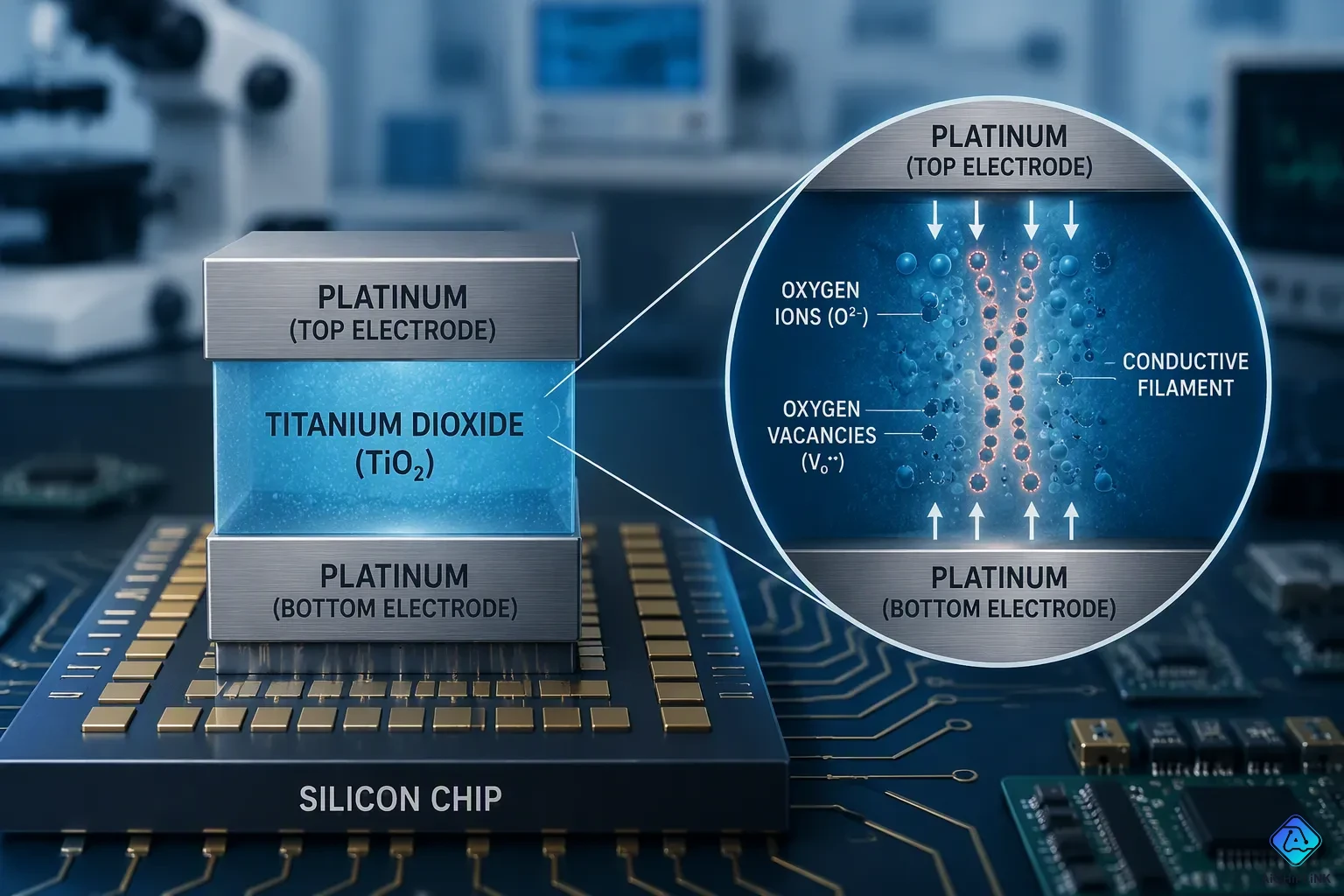
A memristor is a two-terminal electrical part that links magnetic flux and electric charge. This device remembers how much charge has flowed through it. It keeps its resistance state even after the power turns off. Engineers call this property non-volatility. The memristor holds a special place in circuit theory. It is the fourth fundamental circuit element, along with the resistor, the capacitor, and the inductor. Leon Chua predicted this component in 1971. HP Labs later built a working memristor in 2008. Its resistance changes with current direction and history. This behavior makes the memristor useful for memory and computing.
Key Takeaways
-
A memristor remembers the current that flowed through it before. It keeps its resistance state even without power, so it has non-volatile memory.
-
It completes the set of basic circuit parts by linking charge and magnetic flux, unlike the resistor, capacitor, or inductor.
-
Its simple metal-oxide-metal design uses ion movement to build conductive filaments, which allows resistance to switch back and forth.
-
Memristors can hold several levels of resistance and handle both storage and processing. This cuts down on energy use in tasks that involve a lot of data.
Basic Introduction to Memristor
Definition and Core Property
A memristor is a two-terminal electrical part that does not work in a straight line. It makes a connection between magnetic flux and electric charge. This connection means the device controls or limits the flow of current. It also recalls how much charge has passed through it before. The memristor has a size equal to magnetic flux divided by electric charge. That size is the same as resistance. So the device acts like a resistor whose value depends on its own past. Engineers use a differential equation to explain this behavior. The equation connects how fast flux changes to the current at any moment. The device keeps information as a resistance value, not as a charge on a plate.
This behavior shows up clearly in the lab. A memristor's current-voltage curve makes a pinched hysteresis loop. The loop crosses at the origin, which is a clear sign of memristive behavior. Some devices, such as Au/BiFeO3/Pt/Ti and Au/Nb_xO_y/Al2O3/Nb, show non-zero crossing because of capacitive and inertia effects. The hysteresis loop also moves as frequency goes up. The crossing points shift away from the origin. At high frequencies, the current-voltage curve turns into a straight line. Fourier analysis of the current response shows harmonic parts that change with frequency and amplitude. These harmonics prove the device is not linear.
Compared to Other Elements
The memristor is the fourth basic circuit element. The resistor, the capacitor, and the inductor are the other three. Each of those elements has a set job. A resistor links voltage and current. A capacitor links voltage and charge. An inductor links current and flux. The memristor completes the group by linking charge and flux. Unlike the others, it keeps a memory of past current. A capacitor stores energy in an electric field. An inductor stores energy in a magnetic field. The memristor stores information in its resistance. That memory is why the device is non-volatile. It keeps its resistance state after the power turns off.
That memory gives the memristor real benefits over transistors in memory uses. It allows high-density storage through multiple resistance states and crossbar architectures. It also gives better endurance and data retention. A memristor keeps its state without power, so it avoids the static power drain of transistor-based memory. It switches at lower voltages with femtojoule-scale energies. By joining computation and storage, it cuts the energy spent on moving data. These traits matter for data-heavy tasks.
Retention tests support this non-volatility. The table below sums up measured behavior.
| Condition | Observation |
|---|---|
| 358 K | Data retention lifetime passes the standard 10-year requirement |
| 358 K and 400 K annealing | Very small effect on resistance ratio for up to 10 years |
| 500 K over a decade | Resistance ratio drops by about 20% |
| 600 K | Resistance gets worse over days; switching ability is harmed |
A 2H-MoS2 device tested in a vacuum chamber showed a resistance ratio of 1.6. It needed no forming process. Its non-filamentary switching comes from defect migration under an electric field. The device was 29.4 μm wide. This basic introduction to memristor behavior shows why the component matters.
How a Memristor Works
Resistance Switching and Memory
A memristor changes its resistance when current flows through it. The direction of that current sets the new resistance level. Reverse the current, and the resistance moves the other way. This programmable resistance is the heart of the device. It acts as a function of memory charge, where past current shapes present behavior.
Scientists model this nonlinear dynamic behavior with differential equations. Several models capture how the internal state changes over time.
-
The Biolek window model uses a state variable and a window function. The window stops the state from reaching unphysical limits.
-
The Simmons tunnel barrier model describes conduction through tunneling. Its state variable tracks the barrier width.
-
The TEAM model only changes state when current crosses a set threshold. This makes it fast for digital circuits.
-
The VTEAM model extends TEAM to voltage control. It uses separate equations for each voltage range.
Researchers validate these models in several ways. They build emulator circuits with commercial ICs such as the AD844 and TL082. They run non-volatility tests to confirm the state survives power-off. Monte Carlo analysis checks robustness against component variations. Breadboard prototypes confirm real-world operation. Many emulators pass high-frequency testing up to 26.3 MHz and 30 MHz by showing pinched hysteresis loops. A chaotic Jerk circuit also demonstrates the emulator's function in complex systems.
Non-Volatility and Analog Behavior
The memristor keeps its resistance state after power shuts down. This non-volatile property separates it from volatile memory. Long-term retention tests support this claim. A TaOx-based OxRRAM stack and a reference HfO2-based stack both held their states across 30 days of device-to-device testing. The optimized TaOx stack showed improved retention in both the low-resistance state and the high-resistance state.
The table below shows retention results for a Ta/HfO2/Pt stack.
| Test condition | Retention result |
|---|---|
| Room temperature, over 1 month | Both LRS and HRS retained without noticeable degradation |
| 150 °C, 8 resistance states | Each state stable after more than 10^4 s |
| Arrhenius extrapolation at 85 °C | Extrapolated retention of 7 × 10^4 years |
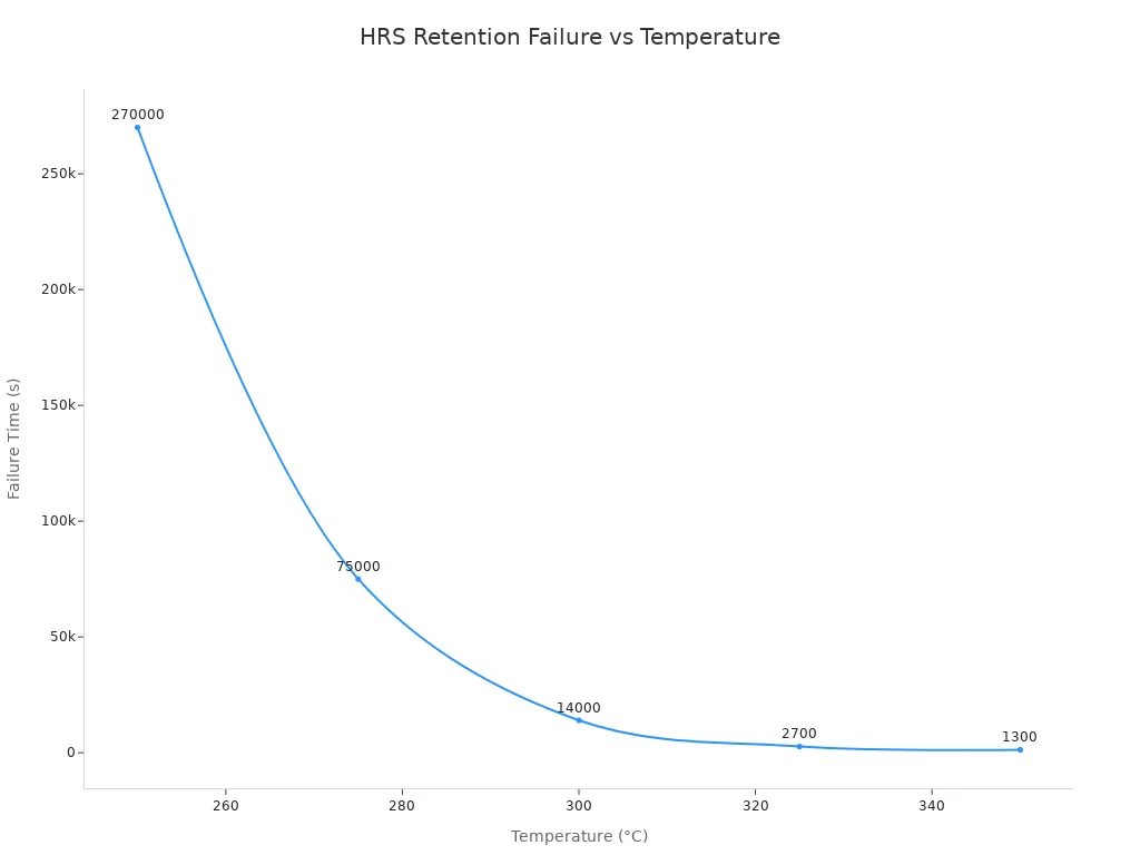
A memristor can also store multiple resistance levels. This enables analog behavior instead of just two binary states. The device moves through a range of values, much like a dimmer switch rather than a simple on-off toggle.
The physical mechanism behind switching involves oxygen vacancies. In oxide-based devices such as TiO2, an applied electric field drives oxygen vacancies to drift and accumulate. They form conductive pathways that lower resistance and create the low-resistance state. Reversing the voltage polarity partially ruptures those paths and restores the high-resistance state. Resistance switching comes from reversible defect movement, not permanent structural breakdown.
As the excitation frequency increases, the hysteresis loop gradually decreases in size and approaches a nearly linear response. At higher frequencies, oxygen vacancies cannot fully follow the rapidly changing electric field, reducing filament growth and weakening resistance modulation.
Microscopy tools help confirm these effects. Scanning electron microscopy, transmission electron microscopy, atomic force microscopy, X-ray diffraction, and Raman spectroscopy reveal surface morphology, crystal structure, and defect distribution. These methods link nanoscale material properties to electrical performance.
Memristor Structure
Metal-Oxide-Metal Design
A memristor uses a simple sandwich-like structure. The design places a thin oxide layer between two metal electrodes. This metal-oxide-metal stack is easy to build. Standard fabrication follows a clear sequence.
-
Deposit the active oxide layer using atomic-layer deposition or sputtering.
-
Define nanoscale electrodes such as platinum, titanium nitride, or silver using lithographic patterning.
-
Apply defect engineering through annealing or plasma treatment to tune resistive switching behavior.
-
Use back-end-of-line processes for hybrid CMOS integration.
The typical oxide layer is very thin. It measures only 3 to 10 nanometers. Common oxides include TiO2, TaOx, HfO2, and SiNx.
This simple structure offers real benefits. It supports fast reading and writing speeds. The design scales well to smaller sizes. It allows high-density memory arrays. Manufacturing costs stay low. The process works with standard CMOS fabrication lines. These advantages make the memristor practical for production.
Ion Migration and Conductive Filaments
A memristor changes its resistance through ion migration. An applied electric field moves ions inside the oxide layer. These ions form tiny conductive paths called filaments. The filaments bridge the two electrodes and lower the resistance. Reversing the voltage dissolves the filaments and raises the resistance again.
Scientists use advanced microscopes to watch this process in real time. Operando STEM studies visualize the action directly. One study used a special holder inside an FEI Titan G2 80-200 ChemiSTEM microscope. A Keithley 2602A source meter applied bias sweeps during imaging of a MoS2-based memristor. The images showed silver conductive filaments forming and dissolving during switching.
The filaments come in many sizes. They range from a few angstroms up to more than 10 nanometers. Silver ions move through several pathways. They travel along the MoS2 surface. They go through van der Waals gaps. They cross disrupted MoS2 layers. They move into adjacent MoS2 bundles. The silver electrode acts as a reservoir for filament growth. Small bias voltages can drive internal silver migration before and after switching.
Energy-dispersive X-ray spectroscopy mapping confirmed these observations. It showed silver filament formation during SET operations and complete dissolution after RESET. These real-time images help explain cycle-to-cycle variability, failed switching, and slow RESET events. The nanoscale view gives engineers the insights they need to improve memristor reliability.
History and Significance
From Theory to Physical Device
Leon Chua described and named the memristor in 1971. He worked from mathematical symmetry in circuit theory. He noticed a missing link between charge and flux. That insight predicted a fourth fundamental element. The idea sat unused for decades. No one could build a working device.
HP Labs changed that in 2008. Their team built a physical memristor using a thin titanium dioxide film. This device showed the pinched hysteresis loop Chua predicted. The discovery sparked new interest in memristor research. Scientists finally had a real component to study.
The memristor stands apart from other circuit elements. It is the only fundamental element that can directly implement memory and logic computation between electronic signals. A resistor cannot remember. A capacitor and an inductor store energy, not information. The memristor combines storage and processing in one place. This dual function opens doors for new computing designs.
Applications and Potential
Engineers see many uses for this technology. Non-volatile random access memory offers one path. A memristor keeps its state without power. This trait suits non-volatile random access memory well. It also fits memristive-based random access memory designs. These memories could replace flash storage with faster speeds and longer life.
Neuromorphic computing is another promising field. The memristor mimics how brain cells pass signals. It can act as artificial neural network synapses. This makes it a natural fit for brain-inspired chips.
In-memory computing benefits from the memristor's dual nature. Data stays where it is processed. This cuts the energy spent moving data back and forth. One study compared a memristor crossbar against standard hardware on a BERTLarge task. The results appear below.
| Platform | ADP (mm²·s) | Energy (mJ) |
|---|---|---|
| TPU | 2.24 | 71.71 |
| GPU (A100) | 2.04 | 65.84 |
| Memristor Crossbar | 0.03 | 20.44 |
The memristor crossbar achieved 69% energy savings compared to the A100 GPU. It also showed at least 68 times improvement in ADP. These gains show why the memristor matters for data-heavy tasks.
A memristor is a two-terminal part that ties magnetic flux to electric charge. It remembers past current and holds its resistance state without power, so it is non-volatile. Unlike the resistor, capacitor, and inductor, it stores information in resistance. Its simple metal-oxide-metal stack allows ion migration to switch that resistance. Leon Chua predicted this element in 1971, and HP Labs built one in 2008. Today, companies such as Weebit Nano and IBM Research push memristor-based non-volatile memory toward real products. Reliability challenges like variability and endurance remain, but research and commercial adoption keep moving forward.

Written by Jack Elliott from AIChipLink.
AIChipLink, one of the fastest-growing global independent electronic components distributors in the world, offers millions of products from thousands of manufacturers, and many of our in-stock parts is available to ship same day.
We mainly source and distribute integrated circuit (IC) products of brands such as Broadcom, Microchip, Texas Instruments, Infineon, NXP, Analog Devices, Qualcomm, Intel, etc., which are widely used in communication & network, telecom, industrial control, new energy and automotive electronics.
Empowered by AI, Linked to the Future. Get started on AIChipLink and submit your RFQ online today!
Frequently Asked Questions
What makes a memristor different from a resistor?
A resistor keeps one resistance value that never changes. A memristor changes its resistance based on the current that flowed through it before. It remembers past charge. That memory stays even after the power turns off. This non-volatile behavior makes it different from a plain resistor.
Why is the memristor called the fourth fundamental circuit element?
Circuit theory has three basic elements: the resistor, the capacitor, and the inductor. Each one links a pair of electrical quantities. The memristor completes the set by linking charge and magnetic flux. Leon Chua predicted this missing element in 1971.
How does a memristor store information without power?
The device keeps its resistance state after the power shuts down. Oxygen vacancies drift inside the oxide layer and form conductive filaments. Those filaments stay in place without any applied voltage. This non-volatile trait lets the memristor keep data for long periods.
Can a memristor hold more than two states?
Yes. A memristor can store multiple resistance levels instead of just a high and low state. This analog behavior works like a dimmer switch rather than a simple on-off toggle. It fits tasks that need gradual, brain-like signal changes.
What limits memristor adoption today?
Reliability issues remain. Cycle-to-cycle variability, endurance limits, and slow RESET events still challenge engineers. Research groups and companies keep working to improve these areas. Real-world adoption keeps moving forward as the technology matures.