The Ultimate Guide to DPDT Switches for 2026
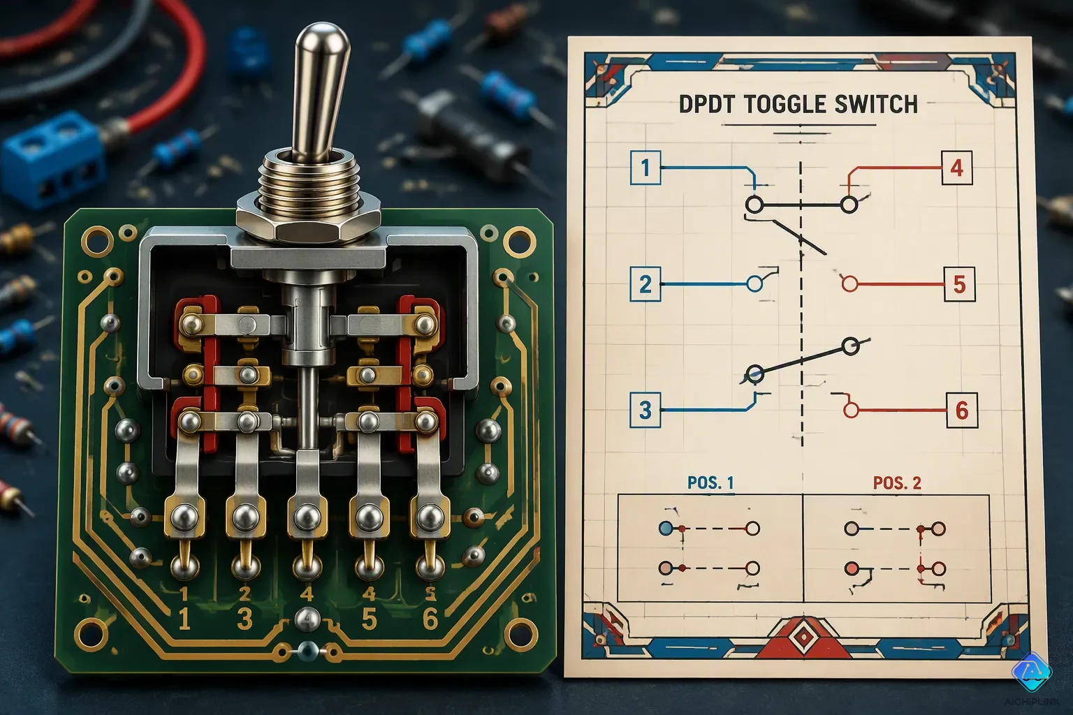
A DPDT (Double Pole Double Throw) switch is an electromechanical part that controls two separate circuits at once. It is great for reversing motor polarity, switching power sources, or routing signals.
Why is this important in 2026? The global switches market is growing from USD 16.46 billion in 2024 to USD 28.29 billion by 2033, a 6.2% CAGR. Toggle switches, including DPDT types, are the biggest part of this market. You find these switches in robotics, car upgrades, and factory automation.
Whether you are wiring a DIY motor controller or designing a safety interlock system, learning the DPDT switch is your first step to control circuits precisely. The Complete Guide ahead covers configurations, wiring, selection, and troubleshooting to help you succeed.
Key Takeaways
-
A DPDT switch can control two separate circuits at the same time, so it's great for reversing motor polarity or switching between two power sources.
-
Pick the right switch type: ON-ON for simple switching, ON-OFF-ON for a safe center-off position, and ON/ON/ON for complex signal routing.
-
To reverse a motor, connect power to the center terminals and cross the wires on the outer terminals in an X pattern to safely switch the polarity.
-
Always match the switch's voltage and current ratings to what your circuit needs, and pick a switch with a DC rating for DC uses to stop arcing.
-
Use a DPDT switch for interlock safety in industrial controls. Its mechanical design stops conflicting actions, like forward and reverse, from turning on at the same time.
The Complete Guide to DPDT Switch Configurations
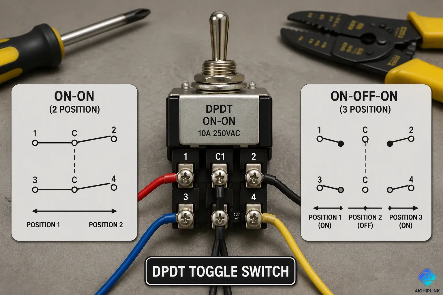
Before you wire anything, you need to understand what makes a DPDT switch different from simpler switches. This section of The Complete Guide breaks down the terminal layout and the three most common configurations you will encounter in real projects.
Poles and Throws Explained
A DPDT switch has two poles and two throws. The pole count shows how many separate circuits the switch controls. With two poles, you can handle two independent circuits at the same time. The throw count shows how many output paths each pole can connect to. Each pole has two throws, so it can send electricity to one of two possible outputs.
This setup gives you six terminals on the back of the switch. Two terminals act as the common connections, one for each pole. The other four terminals are the throws. Think of the common terminals as the inputs and the throws as the outputs. When you flip the actuator, both commons connect to their own throws at the same time.
Inside, a DPDT switch is made of two SPDT switches linked together. One physical move operates both circuits at once. This link makes the switch perfect for jobs where two circuits must change together, like reversing a motor or switching between two audio sources.
ON-ON, ON-OFF-ON, and On/On/On Variants
The most common DPDT setup is ON-ON. This switch has two positions, and each position connects the commons to a different set of throws. You can find this type as either latching or momentary. A latching ON-ON switch stays in whatever position you set. A momentary version springs back to its resting spot when you let go. Use the latching type for power source selection or motor direction control. Use the momentary type for jog controls or short-term activation.
The ON-OFF-ON type adds a center-off position. This middle spot disconnects both commons from all throws, breaking both circuits fully. This setup is useful for motor control because you can stop the motor completely before reversing direction. The center spot also gives a safe neutral state for equipment maintenance. If the switch has built-in indicator lights, you will find an extra terminal for each light, needing a ground wire for DC systems or a neutral wire for AC systems.
The ON/ON/ON type works differently. Its middle spot connects the commons to both the normally open and normally closed throws at the same time. This setup lets you combine signals or create special wiring patterns that the other types cannot do. You might use it for complex signal routing or for making a crossover connection between two circuits.
For DC motor polarity reversal, you wire the power source to the center common terminals. Then you make an X crossover pattern on the outer terminals, connecting top-left to bottom-right and top-right to bottom-left. The motor leads attach to either the top or bottom pair. Flipping the toggle changes the voltage from positive to negative, which changes the motor direction.
For A/B source selection, you skip the crossover entirely. Connect your device to the center common terminals. Connect Power Source A to the top two terminals and Power Source B to the bottom two terminals. This setup lets you switch one device between two power sources, like main power and battery backup. Using the X crossover pattern here creates a dead short between the two power sources when you throw the switch, so keep the wiring straight.
Before you connect anything, check the terminal layout against the datasheet. Check the switch ratings against your load. For larger motors, use the DPDT switch to control a relay or contactor instead of switching the full load directly. This method extends the switch life and prevents contact damage.
How DPDT Switches Work
Learning the inner parts helps you see why DPDT switches work so well. The design uses two sets of contacts that sit in a balanced layout, moved by the same spring or linkage. This shared setup makes sure both circuits move at the same time and in the same way. That timing is the key to controlling two circuits together.
Internal Mechanism and Switching Logic
A DPDT switch has four main parts inside. The actuator takes in the force from your hand. The contact parts use silver alloy or gold plating to carry electricity and resist wear. The spring stores and releases energy for fast switching. The housing protects everything, and it can come with IP65 or IP67 sealing for tough places.
When you push the actuator, the spring builds up energy until it hits a set point. Then the spring lets go in a quick snap. This snap moves the contacts from one path to the other in an instant. The fast, spring-driven move stops slow contact separation, which cuts down on electrical arcing and gives you steady, repeatable switching.
The switching logic follows a simple pattern:
-
Double Pole means controlling two separate circuits that do not share electricity.
-
Double Throw means each circuit can pick between two outputs.
-
One physical move runs the switching logic of two SPDT switches at the same time.
This joined switching makes control logic simpler. For motor forward and reverse, the switch changes both positive and negative wires together. For safety systems, it cuts one circuit while turning on another. For multi-signal systems, it switches input and output paths together to avoid brief errors.
Center-Off and Interlock Features
The center-off spot gives a neutral state between the two active spots. This middle spot cuts both commons from all throws, fully breaking both circuits. You use this for quick stops in motor control. The motor stops completely before you reverse, which prevents mechanical shock or electrical strain.
Interlock safety stops two conflicting actions from happening at once. In a motor controller, forward and reverse cannot both be on. The DPDT switch's mechanical design makes this impossible. One throw position runs the motor forward. The other throw position runs it reverse. The center spot makes sure it stops fully between them.
This interlock feature guards your equipment from short circuits and mechanical harm. It also keeps operators safe from sudden motion. The Complete Guide stresses this safety point because it sets DPDT switches apart from simpler options. You get built-in protection without extra logic circuits or relays.
The spring snap action also adds to safety. It stops partial contact states where circuits might briefly connect wrong. Each switch action finishes fully and clearly, leaving no unclear middle state.
Wiring for Motor Reversal
Wiring a DPDT switch to reverse a motor creates what engineers call an H-bridge setup. The way current moves looks like the letter H on a wiring diagram. This design lets you flip the polarity across your motor terminals with just one move of the switch.
Step-by-Step Guide for DC Motors
First, gather your parts. You need a DPDT switch with a center-off spot, a DC motor, wire, and a power source. The center-off position gives you a physical break in the circuit. This stops the motor without turning off the rectifier, which keeps you safe during repairs or emergency stops.
Follow these wiring steps carefully:
| Wiring Step | Connection Detail |
|---|---|
| DC Positive | Connect to both COM terminals (pins 1 and 6) on the DPDT switch |
| CCW Position | Connect motor terminal A1 to NO1 |
| CW Position | Connect motor terminal A2 to NO2 |
| Diagonal Jumper F1 | Connect F1 to NO1, then jumper diagonally to NC2 |
| Diagonal Jumper S1 | Connect S1 to NO2, then jumper diagonally to NC1 |
| DC Negative | Connect L2 permanently to negative output of bridge rectifier |
The diagonal jumpers make the crossover pattern that flips polarity. When you move the switch one way, current goes through the motor in one direction. Move it the other way, and the current goes the opposite way.
Pick your switch based on these specs:
| Requirement | Specification |
|---|---|
| Voltage Rating | 125-250 VDC minimum |
| Current Rating | 10A minimum (derate 25% for DC) |
| Pole Configuration | DPDT with center-off |
| Contact Material | Silver alloy or gold-plated |
DC motors create higher arc voltage than AC motors. Standard AC toggle switches use zero-crossing arc suppression that does not work in DC circuits. Use a switch rated at least 125VDC with 10A capacity to stop contact pitting and failure.
Common Wiring Mistakes to Avoid
Mixing up common and throw terminals is the most common error. The commons are your inputs. The throws are your outputs. Connect power to the wrong terminals, and your motor will not reverse properly. Always check the datasheet against your physical switch before wiring.
Using the wrong wire gauge causes overheating. The locked-rotor current can go over 30A even if the nameplate shows 4.6A. Make sure the switch and wire gauges can handle this surge. Thin wire heats up, melts insulation, and creates short circuits.
Ignoring switch ratings leads to early failure. Confirm the switch's voltage and current ratings are higher than your circuit's needs. Do not run motors beyond the switch's designed capacity. Too much current wears out contacts quickly.
PLEASE NOTE: if you use manual switches, rapid switching of the motors from forward to reverse can damage the motors due to powerful counter-EMF forces. Please be sure to allow the motor to stop first, before changing direction. This is generally true of any DC motor.
Install protective fusing to guard against field winding shorts. Place a 5A fast-blow fuse in series with the line. This simple addition protects your equipment and prevents costly repairs.
Prevent self-excitation in compound motors. These motors can self-excite if spun with open field windings. Always disconnect power before any mechanical work.
De-energize the circuit before touching any terminals. This prevents short circuits and electric shock. Tighten all connections firmly. Loose connections generate heat and cause damage. Mount the switch securely in a stable location. Keep it dry and clean using enclosures in harsh environments. Label positions clearly to avoid errors when reversing direction. Stop using the switch if it feels warm, crackles, or becomes hard to flip. Inspect the wiring immediately.
The Complete Guide emphasizes these safety points because they prevent both equipment damage and personal injury. Follow each step precisely, and your motor reversal project will work reliably for years.
Common Applications and Interlock Safety
DPDT switches are used in many real systems, not just for simple motor control. Two main uses are A/B source selection in audio systems and interlock safety in machines. Both uses depend on the switch's ability to control two circuits at once with one movement.
A/B Source Selection in Audio
Professional audio systems often need to switch between two amplifiers but use one set of speakers. A DPDT switch does this job well. You connect the common terminals to your speakers. Then wire Source A to one set of throws and Source B to the other. Flipping the toggle sends the speaker signal to the amplifier you pick.
For stereo systems, you need a 4PDT switch or two DPDT switches together. The four connections—left positive, left negative, right positive, right negative—must switch separately. They cannot share a common ground. This stops short circuits and ground loops that cause hum or damage equipment.
The contact behavior is very important here. Your switch must be "break before make" type. This design disconnects one source before it connects the other. Connecting both amplifiers at the same time would create a dangerous short circuit. The wiring layout follows a simple pattern:
| Source A (Amp 1) | Common (Speakers) | Source B (Amp 2) |
|---|---|---|
| A1 L+ | SP L+ | A2 L+ |
| A1 L- | SP L- | A2 L- |
| A1 R- | SP R- | A2 R- |
| A1 R+ | SP R+ | A2 R+ |
You need no extra parts for this setup. Just binding posts, wires, and the switch. The DPDT design makes sure both channels switch together. This keeps perfect stereo balance.
Interlock Safety in Industrial Controls
Industrial machines need protection against conflicting actions. A DPDT switch gives mechanical interlock safety without complex logic circuits. Think of a conveyor system with forward and reverse. The switch's center-off position makes sure the motor stops fully before it changes direction.
The mechanical design makes it impossible to activate both at once. One throw position runs the motor forward. The other runs it reverse. The center position breaks both circuits completely. This built-in interlock stops short circuits that would happen if both directions started at the same time. It also keeps operators safe from sudden, unexpected movement.
You can use this interlock idea beyond motors. Use DPDT switches to stop two hydraulic valves from opening at once, to switch between two safety systems, or to make sure one power source disconnects before another connects. The Complete Guide stresses this safety benefit because it comes free with the switch design—no extra relays or control logic needed.
The spring snap action adds another safety layer. It stops partial contact states where circuits could briefly connect wrong. Each switch action finishes fully and clearly. There is no unclear middle state. This reliability makes DPDT switches a trusted choice for safety-critical industrial uses.
How to Select the Right DPDT Switch
Picking the right DPDT switch for your project means matching its specs to what your circuit needs. If you choose wrong, the switch may fail early or work unsafely. Focus on electrical ratings, contact materials, and environmental protection.
Key Electrical Ratings
Voltage and current ratings are the most important specs. Pick a switch with a voltage rating higher than your circuit's maximum voltage. Do the same for current. For example, if your motor draws 8 amps at 12 volts DC, choose a switch rated for at least 10 amps at 125 volts DC. Going over these ratings makes the contacts overheat. The heat melts the contact material. This causes a short circuit or permanent failure. The arc that forms when switching DC current is harder to stop than AC. A switch rated only for AC will fail fast in a DC circuit.
Beyond voltage and current, think about these selection points:
-
Contact type: Choose break-before-make contacts to stop shorting between circuits during switching.
-
Actuator style: Match the actuator (toggle, rocker, slide, pushbutton) to your user interface design.
-
Mounting type: Use panel mount for external controls or PCB mount for compact systems.
-
Terminals: Pick solder, screw, or quick-connect terminals based on how you install.
-
Certifications: Check that the switch has UL, CE, or CSA approvals to meet safety standards.
-
Durability: Look at the mechanical and electrical cycle ratings to ensure the switch lasts for the expected number of uses.
Also think about the switch's size and default state. Decide if you need momentary or maintained (latching) action. Match the number of positions to your application. A standard DPDT switch has two positions, but the ON-OFF-ON type has three.
Contact Material and Environmental Protection
The contact material decides how the switch handles current. Silver alloy contacts work well for high-current uses like motors and power supplies. Gold contacts are better for low-level signals, such as audio or sensor inputs, because gold does not oxidize. Oxidation on silver contacts can block the tiny currents in signal circuits. Gold plating stops this problem.
For outdoor or harsh places, the switch's IP rating matters. The table below shows the most common protection levels:
| IP Rating | Protection Capability |
|---|---|
| IP65 | Fully dust-tight; withstands water spray from a nozzle |
| IP66 | Fully dust-tight; withstands powerful water jets |
| IP67 | Fully dust-tight; immersible in water up to 1 meter for 30 minutes |
For outdoor use, pick a switch with an IP rating of IP65 or higher. IP67 is the recommended rating for automotive and marine equipment. Sealed switches also resist vibration and dust. This protection extends the switch life in tough conditions. The Complete Guide recommends always checking the datasheet for exact ratings before installation.
Troubleshooting DPDT Switch Failures
Even a reliable DPDT switch can fail over time. Knowing how to spot the problem saves you hours of frustration. Faults fall into two main categories. Mechanical faults affect the physical parts. Electrical faults involve the flow of current. Each type has its own warning signs.
Identifying Mechanical and Electrical Faults
Mechanical faults happen when the moving parts wear out or break. A stuck actuator occurs when dirt or debris blocks the internal mechanism. The toggle may feel stiff or refuse to move. Worn contacts develop after many switching cycles. The metal surface becomes pitted from electrical arcing. This wear increases resistance and generates heat. Broken springs cause the actuator to feel loose. The switch may not stay in its position or may fail to return to center.
Electrical faults involve problems with current flow. A short circuit happens when the contacts connect when they should not. This can blow fuses or damage your equipment. An open circuit occurs when the contacts fail to connect at all. Your device gets no power even when you flip the switch to the correct position. An intermittent connection is the trickiest fault. The switch works sometimes but not others. Vibration or temperature changes can cause the connection to come and go.
Testing with a Multimeter
A multimeter is your best tool for diagnosing switch problems. Set the meter to continuity mode or resistance mode. The continuity mode beeps when the probes touch two connected points.
Start by disconnecting the switch from power. Remove all wires from the terminals. Place one probe on the common terminal of the first pole. Touch the other probe to each throw terminal of that same pole. Flip the switch to its first position. The meter should beep between the common and one throw. Flip to the second position. The beep should move to the other throw. Repeat the same test for the second pole.
If you get a beep between the common and both throws at the same time, you have a short circuit. If you get no beep in any position, you have an open circuit. If the beep comes and goes when you wiggle the actuator, you have an intermittent connection. The Complete Guide recommends replacing any switch that fails these tests. Do not try to repair a faulty switch. Replace it with a new one that matches your original specifications.
DPDT vs Other Switch Types
You now understand how a DPDT switch works and where to use it. But how does it compare to simpler switches? Knowing the differences helps you pick the right component for each job. This section breaks down the four main switch types and explains when you need the extra capability of a DPDT.
Comparing DPDT with SPST, SPDT, and DPST
Every switch type has a specific job. The table below shows how they differ in terminals, poles, and throws.
| Switch Type | Poles | Throws | Terminals | Function |
|---|---|---|---|---|
| SPST | 1 | 1 | 2 | Simple ON-OFF for one circuit |
| SPDT | 1 | 2 | 3 | Routes one input to one of two outputs |
| DPST | 2 | 1 | 4 | Turns two circuits on or off together |
| DPDT | 2 | 2 | 6 | Routes two inputs to two outputs each |
The pole count tells you how many separate circuits the switch controls. The throw count tells you how many output paths each pole can reach. An SPST switch acts as a simple gate. It opens or closes one circuit. An SPDT switch routes a single input to one of two outputs. This works well for A/B selection of one signal. A DPST switch controls two circuits but only turns them on or off together. It cannot change outputs.
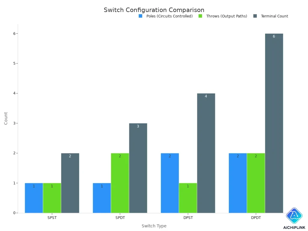
A DPDT switch combines the best features. It has two poles like a DPST, but each pole has two throws like an SPDT. This gives you six terminals and the ability to route two separate inputs to two alternative outputs. The two poles move together mechanically, so both circuits change at the same time.
When to Choose DPDT Over Alternatives
You need a DPDT switch when your project requires more than simple on-off control. The main scenarios include:
-
Forward and reverse control of DC motors: Cross-switching the power lines through a DPDT switch reverses motor direction without a PLC or complex logic controller.
-
Synchronous dual-circuit switching: You can control two independent circuits at once, making DPDT ideal for coordinated switching of two signals.
-
Power reversal and redundancy: Industrial automation, motor control systems, and power backup systems need two circuits switched together.
Unlike a DPST switch, which only turns two circuits on or off, a DPDT provides two throws per pole. This enables polarity reversal or selecting between two distinct states for both circuits. You need a DPDT when you must reverse voltage polarity or switch between two signal paths for two circuits at once.
For simpler tasks, choose the simpler switch. Use an SPST for a basic light or fan. Use an SPDT for single-circuit A/B selection. Use a DPST when you need to cut two power lines together. The Complete Guide recommends matching the switch complexity to your actual needs. This saves money and reduces failure points.
You now understand DPDT switches. These versatile components control two independent circuits simultaneously. The ON-ON, ON-OFF-ON, and ON/ON/ON configurations serve different purposes. Proper wiring matters most for motor reversal projects. Always match your switch's electrical ratings to your circuit's demands. Consider the environment too—IP ratings protect against dust and moisture.
Now you can confidently select, wire, and troubleshoot DPDT switches for your next project in 2026. As technology evolves, DPDT switches remain a reliable, cost-effective solution for modern control systems. Have you used a DPDT switch in a creative way? Share your experience or ask questions in the comments below.

Written by Jack Elliott from AIChipLink.
AIChipLink, one of the fastest-growing global independent electronic components distributors in the world, offers millions of products from thousands of manufacturers, and many of our in-stock parts is available to ship same day.
We mainly source and distribute integrated circuit (IC) products of brands such as Broadcom, Microchip, Texas Instruments, Infineon, NXP, Analog Devices, Qualcomm, Intel, etc., which are widely used in communication & network, telecom, industrial control, new energy and automotive electronics.
Empowered by AI, Linked to the Future. Get started on AIChipLink and submit your RFQ online today!
Frequently Asked Questions
Can You Use a DPDT Switch for Both AC and DC?
Yes, but you must check the voltage rating carefully. DC arcs are harder to extinguish than AC arcs. Choose a switch with a DC voltage rating at or above your circuit voltage.
What Happens If You Exceed the Current Rating?
The contacts overheat and degrade quickly. This causes welding, arcing, or fire. Always pick a switch rated 25% above your maximum load current.
Do You Need Break-Before-Make or Make-Before-Break?
Use break-before-make for motor reversal and power switching. It disconnects one circuit before connecting the other. This prevents dangerous short circuits between sources.
Can You Use a DPDT Switch for a 3-Phase Motor?
No. A DPDT switch controls two circuits. A 3-phase motor needs three poles. Use a 3PDT switch or a contactor instead.