You can connect l298n to raspberry pi 5 for good motor control. When you set up the l298n motor driver with your raspberry pi, always check the wires and voltage levels. Many people break their pi or l298 by connecting GPIO pins to more than 3.3V or by wiring the 5V pin on the l298n the wrong way.
Tip: Never use the 5V output on the l298n as an input for your raspberry pi. Always check your wires to stop high voltages from going to logic pins on either device.
If you use safe wiring, you keep your raspberry pi, l298n, and motor driver safe from common mistakes. This careful way helps your raspberry pi motor control project work well.
Key Takeaways
-
Always use different power supplies for your motors and Raspberry Pi. This helps stop damage and keeps things working well.
-
Connect all grounds from the Raspberry Pi, L298N, and motor power supply together. This keeps signals steady and safe.
-
Check your wiring and GPIO pin connections before turning on power. This helps stop damage and makes sure the motors work right.
-
Use PWM signals on the L298N enable pins to change motor speed. Set GPIO pins to pick which way the motor turns.
-
Test your GPIO pins and code with easy scripts before running motors. This helps you find wiring or code mistakes early.
Components for L298N Motor Driver
Parts List
You need several parts to connect the l298n motor driver to your raspberry pi. The l298n motor driver module lets you control two motors at once. It works well with both DC motors and stepper motors. You can use it for small robots or other projects that need motor control.
Here is what you need:
-
l298n motor driver module (dual bidirectional motor driver)
-
Raspberry Pi 5
-
Two DC motors or one stepper motor
-
Jumper wires for connections
-
External power supply for motors (like a battery pack)
-
Small screwdriver for terminal blocks
The l298n motor driver module has two channels, so you can control two motors. It uses a dual H-bridge motor driver IC. The module has screw terminals for easy wiring. You connect the motor wires to the output pins. The input pins let you set the direction and speed. The enable pins must be high for the motors to run. The l298 based motor driver works with both 3.3V and 5V logic, so it matches the raspberry pi.
Here is a quick look at the main specs:
| Parameter | Value |
|---|---|
| Motor Supply Voltage | Up to 46V |
| Maximum Current per Channel | 2A |
| Logic Voltage | 5V |
| Driver Voltage Range | 5-35V |
| Logic Current | 0-36mA |
| Maximum Power | 25W |
Power Supply Tips
You should use a separate power supply for your motors. The l298n can handle motor voltages from 6V to 12V for most projects. If you use the raspberry pi to power the motors, you might overload it. Motors can draw a lot of current, sometimes up to 2A per channel. This can cause your pi to reboot or even get damaged.
Tip: Always connect the grounds of the l298n motor driver and the raspberry pi together. This keeps the signals steady and safe.
Use the raspberry pi’s 5V pin only for the logic part of the l298n. Power the motors with a battery pack or another supply. This setup keeps your raspberry and l298 safe and helps your motors run smoothly.
Wiring L298N to Raspberry Pi 5
Connecting the L298N to your Raspberry Pi 5 lets you control motors safely and efficiently. This wiring guide will help you make the right wiring connections and avoid common mistakes. Follow each step to connect L298N, set up the motor driver, and ensure your motors run smoothly.
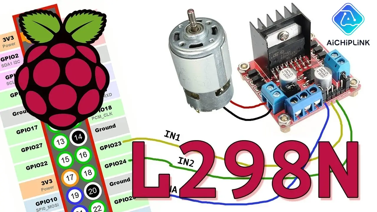
Connect L298N Inputs to GPIO
You need to connect the input pins of the L298N to the correct GPIO pins on your Raspberry Pi. These connections let the Pi send signals to the motor driver and control the motors. Here is a simple way to connect L298N inputs to the Pi:
-
IN1 → GPIO 18
-
IN2 → GPIO 19
-
IN3 → GPIO 20
-
IN4 → GPIO 21
You can also use another common setup:
-
IN1 → GPIO 12
-
IN2 → GPIO 16
-
IN3 → GPIO 20
-
IN4 → GPIO 21
Tip: Always double-check your wiring before powering up. Wrong connections can damage your Raspberry Pi or the L298N.
To connect L298N, use jumper wires from the Pi’s GPIO header to the IN1, IN2, IN3, and IN4 pins on the L298N motor driver module. Make sure the wires are secure and not loose. This setup allows you to control the direction and speed of two motors.
Power and Ground Connections
The L298N needs a separate power supply for the motors. Do not use the Raspberry Pi to power the motors. The Pi cannot handle the high current that motors need. Use a battery pack or a dedicated power adapter for the motor power supply. Connect the L298N VCC pin to the positive terminal of your motor power supply (usually 6V to 12V for most small motors).
You must connect all grounds together. This means you connect the ground (GND) pin of the L298N to both the ground of the Raspberry Pi and the ground of the motor power supply. This common ground keeps the signals steady and prevents problems like erratic motor movement or damage to your devices.
-
Connect L298N GND to Raspberry Pi GND.
-
Connect L298N GND to the motor power supply ground.
Note: Sharing a common ground is critical. If you skip this step, your motors may not work, or you could damage your Raspberry Pi or L298N.
The L298N motor driver module has a 5V pin. Only connect this to the Pi’s 5V pin if you use a 12V motor supply and the onboard regulator is enabled. Never use the L298N 5V pin as a power source for the Pi.
Motor Terminal Wiring
Now you need to connect motors to the L298N. The module has two sets of output terminals, usually labeled OUT1/OUT2 and OUT3/OUT4. These are for the two motors.
-
Connect your first motor to OUT1 and OUT2.
-
Connect your second motor to OUT3 and OUT4.
Make sure the wires are tight in the screw terminals. If you want to reverse the direction of a motor, swap the wires on the output terminals.
Warning: The L298N causes a voltage drop between the input voltage and the motor outputs. For example, if you supply 5V, your motor may only get about 3V. At higher currents, the voltage drop can reach up to 3V or more. Always use a motor power supply that is higher than your motor’s rated voltage to account for this drop.
Here is a quick table showing typical voltage drops:
| Motor Current (A) | Voltage Drop (V) |
|---|---|
| 1 | 1.8 – 3 |
| 2 | Up to 5 |
This voltage drop is normal for the L298N. It happens because of the way the motor driver works. Plan your motor power supply with this in mind.
Safety Tip: Never connect motors that draw more than 2A per channel. Overloading the L298N can cause it to overheat or fail.
Logic Level Compatibility and Safe Wiring
The Raspberry Pi uses 3.3V logic on its GPIO pins. The L298N can accept 3.3V signals, but some modules work better with 5V logic. If you notice unreliable motor control, you may need a logic level shifter. Most users find that direct wiring works for basic projects.
-
Keep your wiring neat and avoid crossing wires.
-
Use a wiring diagram to plan your connections.
-
Check all connections before turning on the power.
Reminder: Always power the motors and the Pi separately. Connect L298N to the Pi only for control signals and ground.
By following this wiring guide, you can connect L298N to Raspberry Pi 5 safely. You will have reliable motor connections and avoid common wiring mistakes.
Interfacing L298N with Raspberry Pi 5
GPIO Pin Assignments
When you start interfacing l298n with your Raspberry Pi 5, you need to choose the right gpio pins for the motor driver inputs. The gpio pin assignments are important because they decide how you control motors and set their direction. Many community projects use specific pins for this purpose.
-
GPIO 17 and GPIO 18 are the most common pins for IN1 and IN2 on the l298n. These pins let you set the direction of your DC motor.
-
You can use other gpio pins for IN3 and IN4 if you want to control a second motor. GPIO 20 and GPIO 21 are good choices for these inputs.
Tip: Always check your wiring and make sure you use the correct gpio pin assignments in your code. If you mix up the pins, your motors may not spin as expected.
Here is a quick list of typical gpio pin assignments for bidirectional motor control with the l298n:
-
IN1 → GPIO 17
-
IN2 → GPIO 18
-
IN3 → GPIO 20
-
IN4 → GPIO 21
You can use these pins to control a dc motor or two motors at once. This setup gives you full control over direction and speed.
PWM Setup for Speed Control
To control the speed of your motors, you need to use pwm (Pulse Width Modulation). The l298n works well with pwm signals from the Raspberry Pi 5. You send a pwm signal to the enable pin of the l298 motor driver. This signal changes the speed of the motor by adjusting the duty cycle.
Most projects use a pwm frequency of about 160 Hz for the l298n. You can set the duty cycle from 0% (motor off) to almost 100% (full speed). If you want to control a dc motor smoothly, start with a duty cycle of 50% and adjust as needed.
Here is a table showing typical pwm settings for l298 motor control:
| PWM Frequency | Duty Cycle Range | Effect on Motor |
|---|---|---|
| 160 Hz | 0% - 100% | 0% = stop, 100% = full speed |
Note: You may need to tune the pwm frequency or duty cycle for your specific motors. Some motors run better at slightly higher or lower frequencies.
You can use the Raspberry Pi GPIO library to set up pwm. For example, you can start with a 50% duty cycle and then increase it to 75% to make the motor spin faster. This method works for both single and bidirectional motor control.
Using WiringPi or Python Libraries
You have several options for controlling the l298n with your Raspberry Pi 5. Many users choose Python libraries because they are easy to use and well-supported. RpiMotorLib is one of the most popular Python libraries for motor control with the l298n. It supports both DC motors and stepper motors, and it works well with the Raspberry Pi 5.
You can also use Mycodo, which recently added support for the l298n on Raspberry Pi 5. Mycodo is still adding features, but it already lets you control motors with the l298 driver. If you want to control motors with simple scripts, you can use the built-in RPi.GPIO library or GPIO Zero. These libraries let you set gpio pins high or low and create pwm signals for speed control.
Tip: Before you connect your Raspberry Pi to the l298n, test your gpio pins. You can do this by:
Using jumper wires to check the hardware connections by hand.
Running a simple script that turns gpio pins on and off.
Using a multimeter to check for good connections.
If your test script works, you know your wiring is correct. If not, check your gpio pin assignments and make sure all wires are secure. This step helps you avoid problems when you start to control a dc motor or use bidirectional motor control.
With the right libraries and careful setup, you can control motors, adjust speed with pwm, and change direction using your Raspberry Pi 5 and the l298n. This setup gives you reliable and flexible motor control for your projects.
Python Code to Connect L298N
Basic Motor Control Example
You can use Python to control a dc motor with the l298n and your raspberry pi. The RPi.GPIO library makes it easy to set up the pins and send signals. Here is a simple example that shows how to connect motors and control their direction.
-
First, set up the GPIO pins for IN1, IN2, and the enable pin.
-
Use PWM on the enable pin to control speed.
-
Set IN1 high and IN2 low to move the motor forward.
-
Set IN1 low and IN2 high to move the motor backward.
-
Set both IN1 and IN2 low to stop the motor.
import RPi.GPIO as GPIO
import time

IN1 = 17
IN2 = 18
ENA = 22  # Enable pin for PWM

GPIO.setmode(GPIO.BCM)
GPIO.setup(IN1, GPIO.OUT)
GPIO.setup(IN2, GPIO.OUT)
GPIO.setup(ENA, GPIO.OUT)

pwm = GPIO.PWM(ENA, 100)  # 100 Hz
pwm.start(0)

def forward(speed):
    GPIO.output(IN1, GPIO.HIGH)
    GPIO.output(IN2, GPIO.LOW)
    pwm.ChangeDutyCycle(speed)

def backward(speed):
    GPIO.output(IN1, GPIO.LOW)
    GPIO.output(IN2, GPIO.HIGH)
    pwm.ChangeDutyCycle(speed)

def stop():
    GPIO.output(IN1, GPIO.LOW)
    GPIO.output(IN2, GPIO.LOW)
    pwm.ChangeDutyCycle(0)

forward(70)
time.sleep(2)
backward(70)
time.sleep(2)
stop()

GPIO.cleanup()
Tip: Always call
GPIO.cleanup()at the end of your script. This resets the pins and helps prevent errors when you run your code again.
Speed and Direction Control
You can control motors with the l298 by changing both speed and direction. The l298n lets you control two dc motors, but you can start with one. Use PWM to set the speed. Change the duty cycle to make the motor go faster or slower. Set the direction by changing which input pin is high.
The script above uses RPi.GPIO to set IN1 and IN2 for direction. It uses PWM on the enable pin to control speed. You can run the motor forward, backward, or stop it. Adjust the speed by changing the PWM duty cycle. For example, use 30 for low speed, 70 for medium, and 100 for high speed.
Many people make mistakes with the logic for direction. If both IN1 and IN2 are high or both are low, the motor stops. Always check your wiring and pin setup. If your motor does not move or moves the wrong way, swap the IN1 and IN2 wires or check your code.
-
Common mistakes include:
-
Swapping IN1 and IN2 or OUT1 and OUT2, which changes the direction.
-
Not providing enough power to the l298n, so the motor does not move.
-
Setting the PWM duty cycle too low, which makes the motor slow.
-
Forgetting to clean up GPIO, which causes errors in later runs.
-
With this setup, you can control a dc motor or control two dc motors with your raspberry pi and l298n. Try changing the speed and direction in your code to see how the motor responds.
Troubleshooting L298N Motor Driver
Power Issues
Power problems are a common reason why your l298n setup does not work as expected. If you see the red LED on the l298n but your motors do not move, you may have an issue with the motor power supply. Always check that you connect the power pins correctly. Never connect the 5V output from the l298n to the VIN pin on your raspberry pi. This can cause damage. You should use a separate power supply for the motors and make sure the logic side of the l298n gets a stable 5V from the raspberry pi.
Tip: Always connect the grounds of the raspberry pi, l298n, and motor power supply together. This step prevents strange behavior and keeps your devices safe.
If your raspberry pi shuts down when you try to run the motors, your power supply may not provide enough current. Use a multimeter to check the voltage and current. Listen for any popping sounds from the l298n. This can mean the chip is damaged from too much current or a wiring mistake.
Motor Not Working
If your motors do not spin, start by checking all wiring. Make sure you connect the enable pins (ENA and ENB) correctly. Many users leave the jumpers on these pins, which stops you from using PWM for speed control. Remove the jumpers if you want to control speed from your raspberry pi.
-
Check that you use the right pin numbering in your code. Mixing up GPIO numbers and physical pin numbers is a common mistake.
-
Make sure you do not supply more than 16V to the onboard 5V regulator. High voltage can burn out the regulator.
-
Confirm that you have not removed the 5V regulator jumper unless you supply 5V from another source.
Note: If the l298n’s power LED is on but the motors do not move, double-check your wiring and power supply.
GPIO or Code Errors
Many problems come from mistakes in your code or GPIO setup. You must set all motor control GPIO pins as outputs before using them. Always use the same GPIO numbering mode, such as BCM, in your code. If you mix modes, your pins may not match your wiring.
Common GPIO and code errors include:
-
Not setting GPIO pins as outputs, which causes runtime errors.
-
Mixing up BOARD and BCM numbering, leading to wrong pin connections.
-
Reusing GPIO pins or conflicting assignments, which triggers warnings.
-
Not disabling GPIO warnings, causing extra messages during code runs.
-
Forgetting to clean up GPIO pins at the end of your program, which can cause problems in later runs.
-
Running code without root privileges, which blocks access to GPIO control.
Tip: Add
GPIO.setwarnings(False)in your script to avoid warning messages. Always callGPIO.cleanup()when your program ends.
You can use a multimeter to check for shorts or breaks in your circuit. Debug your code by testing each pin one at a time. This careful approach helps you find and fix problems quickly.
You can connect and control motors with your raspberry pi by following these steps:
-
Connect your motors to the L298N outputs and wire the input pins to the correct GPIO pins on your pi.
-
Power the L298N with a battery pack and check the red LED to confirm power.
-
Use Python code to set up GPIO pins, control direction, and test movement.
Try different motors or change your code to see new results. Always double-check your wiring and power for safety. You can explore advanced features like stepper motor control or remote operation using the raspberry pi’s GPIO pins.
FAQ
Can I power the Raspberry Pi and motors from the same battery?
You should not power both from the same battery. The motors can cause voltage drops and noise. This can make your Raspberry Pi unstable. Use separate power supplies for the Pi and the motors. Always connect their grounds together.
What happens if I connect the L298N 5V pin to the Pi’s 5V pin?
Warning:
You risk damaging your Raspberry Pi. The L298N 5V pin is an output, not an input. Only use the Pi’s 5V pin to power the logic side of the L298N, not the other way around.
Why do my motors run slowly with the L298N?
The L298N causes a voltage drop. Your motors get less voltage than the supply. If you want faster motors, use a higher voltage power supply within safe limits. Check your wiring and make sure your battery is fully charged.
Can I control stepper motors with the L298N and Raspberry Pi 5?
Yes, you can control stepper motors. The L298N supports both DC and stepper motors. Use Python libraries like RpiMotorLib for easy stepper motor control. Always follow the wiring guide for stepper motors.
Do I need a heatsink for the L298N?
If your motors draw close to 2A per channel, you should use a heatsink. The L298N can get hot during use. A heatsink helps prevent overheating and protects the chip.
Written by Jack Elliott from AIChipLink.
AIChipLink, one of the fastest-growing global independent electronic components distributors in the world, offers millions of products from thousands of manufacturers, and many of our in-stock parts is available to ship same day.
We mainly source and distribute integrated circuit (IC) products of brands such as Broadcom, Microchip, Texas Instruments, Infineon, NXP, Analog Devices, Qualcomm, Intel, etc., which are widely used in communication & network, telecom, industrial control, new energy and automotive electronics.
Empowered by AI, Linked to the Future. Get started on AIChipLink.com and submit your RFQ online today!