The Complete Guide to Coaxial Cable Types and Their Applications
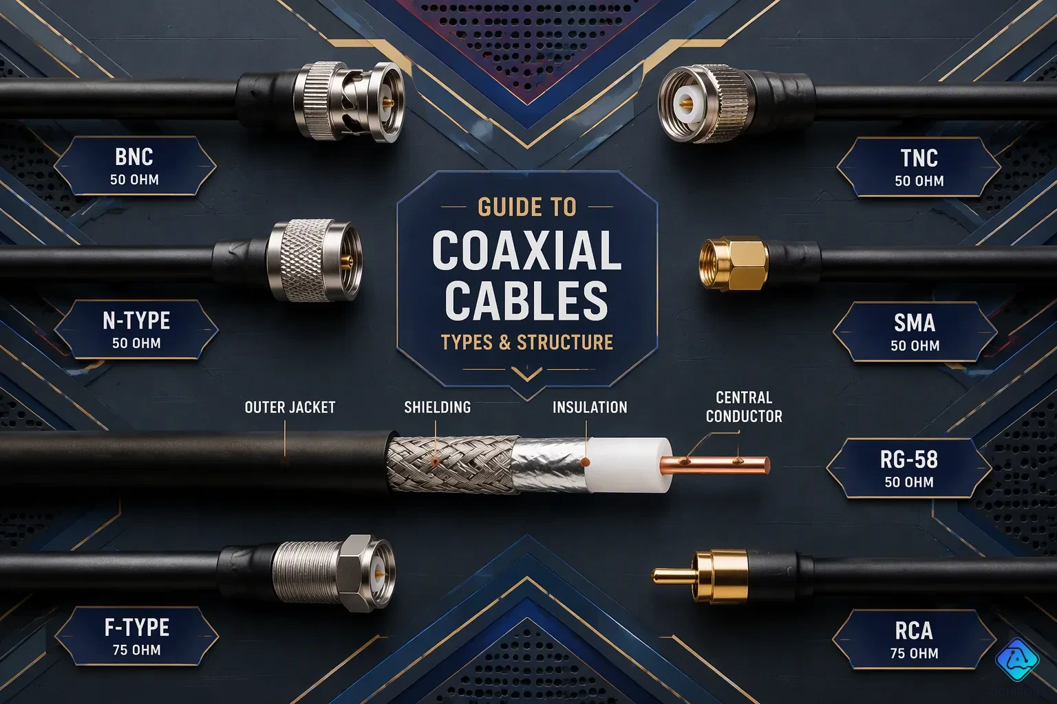
You face a real risk when you pick the wrong coaxial cable. Signal loss, impedance mismatch, or installation failure can ruin your entire setup. A coaxial cable has four layers: a center conductor, a dielectric insulator, a metallic shield, and an outer jacket. Each layer affects performance. This coaxial cable guide covers the main types: RG, LMR, and semi-rigid. You will learn key details like impedance, frequency range, and attenuation. When impedance is wrong, signal reflections weaken power transfer and distort data. Poor cable selection causes noise interference and unstable performance. By the end, you will choose the best coaxial cable for any common use. Think about fiber optic cables vs. coaxial cables: each has its place, and you will know exactly where coax wins.
Key Takeaways
-
First, check the impedance: 50 ohms for RF, 75 ohms for video.
-
Make sure the cable's impedance matches your equipment to avoid losing the signal.
-
Pick thicker cables for long distances to lower signal loss.
-
Use RG-6 for home video and LMR-400 for RF feeds.
-
Ground outdoor cables to keep them safe from lightning strikes.
-
Choose plenum-rated cable for air-handling spaces to meet fire codes.
-
Check the connector types: F-type for TV, N-type for RF.
-
Figure out the loss budget to decide if you need an amplifier.
Coaxial Cable Construction and Key Specifications
To understand how a coaxial cable works, you need to look at its four layers and the electrical specs that set its performance. A "what is coaxial cable" question is answered by knowing these building blocks. Each layer changes how well your signal moves from source to destination.
The Four Layers of a Coaxial Cable
Every coaxial cable has four separate layers. Each one does a specific job.
Inner conductor
The inner conductor carries the electrical signal. Its thickness directly controls signal loss. A thicker conductor means lower resistance and less attenuation. At 1 GHz, RG11 with a 14 AWG conductor loses only 5.6 dB per 100 feet. RG59 with a 20 AWG conductor loses 12.0 dB over the same distance. A smaller gauge (larger AWG number) means less surface area, higher resistance, and greater loss. The inner conductor adds the most resistance because its surface area is much smaller than the outer conductor.
Dielectric insulation
The dielectric surrounds the inner conductor and keeps it correctly spaced from the shield. The material you pick changes signal speed and loss. Solid polyethylene gives a velocity factor near 66%. Foamed dielectrics approach 80%. A 10-meter cable with 66% velocity of propagation has a one-way delay of about 50.5 nanoseconds. At 85% velocity factor, that delay drops to about 39.2 nanoseconds. Lower dielectric constant materials produce higher velocity factors and lower signal loss.
| Material | Dielectric Constant | Velocity Factor | Delay (ns/m) |
|---|---|---|---|
| Cellular TFR | 1.38 | 85% | 1.2 |
| Polyethylene | 2.3 | 66% | 1.55 |
| PVC | 8.2–3.0 | 35–58% | 2.9–1.75 |
Metallic shield (braid, foil, or both)
The shield blocks outside interference and keeps your signal inside. Braided shields offer flexibility. Foil shields provide 100 percent coverage. Many cables combine both layers for maximum protection against noise.
Outer jacket
The jacket protects all inner layers from the environment. Indoor jackets resist chemicals and abrasion. Outdoor jackets add UV protection. Plenum-rated jackets prevent toxic smoke in air-handling spaces.
Critical Electrical Parameters
You need four key specs to pick the right cable.
Characteristic impedance (50Ω vs 75Ω)
Impedance is the cable's opposition to alternating current at a given frequency. The 50 ohm cable gives the best compromise between power handling and low loss. Mathematically, 30 ohms offers best power handling, and 77 ohms gives lowest attenuation. The geometric mean is about 48 ohms, rounded to 50 ohms. The 75 ohm cable provides the lowest attenuation for weak signals. Use a 50 ohm cable for high-power RF transmission. Use a 75 ohm cable for television and video reception.
| Impedance | Application | Key Reason |
|---|---|---|
| 50 ohm | High-power RF, radio transmitters | Best compromise of power and loss |
| 75 ohm | TV, cable TV, video | Lowest attenuation for weak signals |
Attenuation per unit length (dB/100ft)
Attenuation tells you signal loss per 100 feet. Thicker conductors produce lower loss. A larger conductor and dielectric can reduce attenuation by roughly 40 percent compared to RG6 at the same frequency. Compare these common cables at 25°C.
| Cable | Center Conductor | 100 MHz | 500 MHz | 1 GHz | 2 GHz |
|---|---|---|---|---|---|
| RG59 | 20 AWG | 3.4 dB | 8.1 dB | 12.0 dB | 17.5 dB |
| RG6 | 18 AWG | 2.0 dB | 4.6 dB | 6.1 dB | 8.9 dB |
| RG11 | 14 AWG | 1.5 dB | 3.5 dB | 5.6 dB | 7.2 dB |
| LMR-400 | — | 1.0 dB | 2.4 dB | 4.1 dB | 5.3 dB |
Velocity factor and signal speed
Velocity factor describes signal travel speed compared to light in a vacuum. It relates directly to coaxial cable transmission speed. Solid polyethylene gives 66 percent. Foamed dielectrics reach 80 percent or higher. PVC drops to 35 percent. For timing-critical applications, choose a cable with a high and stable velocity factor.
Frequency range and cutoff
Each cable works well up to a certain frequency. Beyond that, loss becomes too high for practical use. Always check the manufacturer's rated range.
Why Impedance Matters for Signal Integrity
Reflection and standing wave ratio (SWR)
When you connect a cable with mismatched impedance, part of the signal reflects back. The reflection coefficient ΓL equals (ZL − Z0) divided by (ZL + Z0). SWR equals (1 + |ΓL|) divided by (1 − |ΓL|). Higher SWR means more reflected energy. The reflected wave gets attenuated traveling back through a lossy cable.
The reflected wave is attenuated on its trip back through a lossy cable. An SWR meter at the radio can therefore indicate a lower ratio than a calibrated measurement at the antenna terminals. The display may look better precisely because part of the forward and reflected energy was dissipated before reaching the meter.
Matching source and load impedance
Match cable impedance to both source and load. A 50 ohm transmitter needs a 50 ohm cable. A 75 ohm TV input needs a 75 ohm cable. Connector impedance must also match. F-type connectors are 75 ohms. N-type connectors are 50 ohms. This explains how a coaxial cable works effectively: impedance must match throughout the entire path.
Common Types of Coaxial Cables

You now understand the four layers and important electrical specs of a coaxial cable. It is time to look at the three main families of coaxial cables you will run into. Each family fixes a different problem. The table below gives you a fast side-by-side view of the most popular types of coaxial cables in each family.
| Cable Family | Impedance | Key Strength | Typical Application |
|---|---|---|---|
| RG-6 (75 Ω) | 75 Ω | Low cost, wide compatibility | Home video, satellite TV |
| RG-11 (75 Ω) | 75 Ω | Lower loss over long runs | Long CATV trunk lines |
| RG-59 (75 Ω) | 75 Ω | Thin and flexible | Short CCTV runs |
| RG-58 (50 Ω) | 50 Ω | Durable, flexible | Amateur radio patch cables |
| RG-213 (50 Ω) | 50 Ω | High power handling | Base station antenna feeds |
| LMR-400 (50 Ω) | 50 Ω | Low loss, flexible | Wireless antenna runs |
| LMR-600 (50 Ω) | 50 Ω | Very low loss | Rugged outdoor installations |
| Semi-rigid (50 Ω) | 50 Ω | Phase stable, full shielding | Microwave and test systems |
These common types of coaxial cables cover almost every real-world setup you will deal with. The sections below explain each family in detail.
RG Series Cables (RG-6, RG-11, RG-59, RG-58, RG-213)
The RG series is the oldest family of coaxial cable types. You can find these cables in homes, offices, and radio shacks all over. Each RG cable does a certain job.
RG-6 and RG-11 for video and long‑distance satellite
RG-6 is the modern standard for home video and broadband. It works with frequencies up to 3 GHz. You use it for satellite TV (950–2150 MHz), digital cable, HD-over-coax CCTV, and cable internet (DOCSIS). The longest runs should be 750–1000 feet for HD video. At 1000 MHz, RG-6 loses about 6.0 dB per 100 feet.
RG-11 is the heavy-duty 75-ohm cable for long-distance runs. It has a larger 14 AWG center conductor than RG-6's 18 AWG. This means lower attenuation: 3.9 dB per 100 feet at 1000 MHz versus RG-6's 6.0 dB. For satellite signals, RG-11 handles runs of 200–400+ feet. RG-6 maxes out at 150 feet for the same job. You pick RG-11 when distance makes RG-6 a bad fit. Common uses include trunk lines in CATV distribution systems, long outdoor runs between buildings, and campus setups where runs go past 200 feet.
RG-59 for CCTV and low‑frequency composite video
RG-59 is a thinner 75-ohm cable with a 20 AWG conductor. It works well for short-distance, low-frequency video signals. You see it in older CCTV systems and composite video connections. Its higher attenuation makes it a bad choice for long runs. For runs under 50 feet, RG-59 does fine. For anything longer, RG-6 or RG-11 gives better results.
RG-58 and RG-213 for RF and amateur radio
RG-58 is a 50-ohm cable with a 20 AWG conductor. It is flexible and works well for short RF patch cables. Amateur radio operators use it to connect transceivers to antenna tuners.
RG-213 is a heavy-duty 50-ohm cable built to military standard MIL-C-17. It has a 7-strand bare copper center conductor (2.14 mm diameter), solid polyethylene dielectric, and 96% bare copper braid shielding. At 30 MHz, it loses only 1.0 dB per 100 feet. Power handling goes up to 1800 watts at 30 MHz. The outer diameter measures 0.405 inches (10.29 mm). You use RG-213 for base station antenna feeds where high power and low loss matter.
LMR Series Cables (LMR‑195, LMR‑240, LMR‑400, LMR‑600)
The LMR family is made up of modern low-loss coaxial cables built for higher frequencies. These cables use advanced foam polyethylene dielectrics to give better performance than older RG types.
Low‑loss design for higher frequencies
LMR cables cut signal loss a lot compared to solid dielectric cables of similar size. The chart below compares attenuation across popular LMR and RG cables at 850 MHz and 1900 MHz.
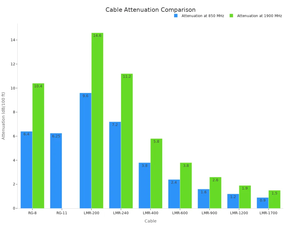
LMR-400 is the most popular model. It works as a modern replacement for RG-8. It has a 2.74 mm center conductor versus RG-8's 2.17 mm. At 850 MHz, LMR-400 loses only 3.8 dB per 100 feet compared to RG-8's 6.4 dB. That is a 40% drop in loss.
Flexible yet low attenuation
LMR cables balance flexibility with low loss. LMR-240 is ultra-flexible, perfect for tight installation spaces and portable setups. Its diameter is only 1/4 inch (6.35 mm). You use it for short jumper assemblies and mobile radio installations. LMR-600 is thicker at 3/5 inch (15 mm) and less flexible than LMR-400, but it gives very low loss: 2.4 dB per 100 feet at 850 MHz. You choose LMR-600 when you need the lowest loss without switching to semi-rigid cable.
Common uses: Wi‑Fi, antenna feeds, mobile radio
LMR cables rule wireless applications. You use LMR-400 for Wi-Fi access point feeds, antenna feeder runs, and cellular installations. LMR-240 works well for GPS, Wi-Fi, and mobile antenna connections. LMR-600 handles rugged outdoor and indoor applications where you need flexibility and low loss. These are the best coaxial cables for RF and wireless systems.
Semi‑Rigid, Corrugated, and Triaxial Cables
Beyond RG and LMR, you will run into three specialty cables for demanding applications. These include semi-rigid coaxial cables, corrugated copper cables, and triaxial cables. Each one solves a certain problem.
Semi‑rigid for precise microwave connections
Semi-rigid cables have a solid copper outer conductor that holds a fixed shape. You cannot bend them over and over. They give total shielding and stable impedance up to very high frequencies. A 0.141-inch semi-rigid cable supports frequencies up to 27 GHz with SMA or 2.92 mm connectors. A 0.086-inch cable reaches 65 GHz with 1.85 mm connectors. A 0.047-inch cable goes up to 110 GHz with 1.0 mm connectors for millimeter-wave systems. Phase stable semi-rigid cables cut measurement uncertainty by reducing temperature-related drift. You find these cables in radar systems, satellite communications, spaceflight hardware, and RF test instrumentation.
Corrugated copper for long outdoor runs
Corrugated cables use a copper outer conductor with a corrugated surface. This design mixes flexibility with the low loss of a solid conductor. You see these cables in long outdoor runs between buildings and in cellular tower installations. They handle higher power levels than flexible braided cables.
Triaxial for high‑noise environments
A triaxial cable has three concentric conductive layers: a center signal conductor, an inner shield, and an outer shield. This third layer gives superior noise rejection. The outer shield catches common-mode interference before it couples into the inner signal path. You use triaxial cables in environments where standard coax fails. Applications include broadcast-grade camera interconnects, low-current precision measurements like electrometer setups, and industrial sensors on high-noise factory floors where ground loops degrade signal integrity. Triaxial cables can achieve greater than 100 dB common-mode rejection above 1 GHz.
How Do I Choose Coaxial Cable for My Application?
You now know the cable families and their specs. The next step is matching a cable to your actual job. The table below gives you a fast starting point. Use it to narrow your options before you dig into the details.
| Application | Recommended Cable | Key Reason |
|---|---|---|
| Cable TV distribution | RG-6 (short), RG-11 (long) | RG-11 has lower loss over distance |
| CCTV surveillance | RG-59 (short), RG-6 (long) | RG-6 handles runs past 200–300 feet |
| Satellite dish | RG-6 with high shielding | Needs 950–2150 MHz range |
| Wi-Fi access point feed | LMR-400 (short), LMR-600 (long) | LMR-600 cuts loss at 5.8 GHz |
| Amateur radio base | RG-213 or LMR-400 | Both handle HF/VHF well |
| Ethernet over coax | RG-6 or RG-59 with baluns | Works up to 200 m |
| Industrial sensors | Triaxial or RG-174 | Triax rejects noise, RG-174 fits tight spaces |
Home and Commercial Video Systems
Video signals are weak. You need low loss and the right impedance. Most video gear uses 75 ohms.
Cable TV distribution (RG-6, RG-11)
RG-6 works for most home cable TV runs. It loses 6.0–6.5 dB per 100 feet at 1 GHz. RG-11 loses only 4.0–5.6 dB over the same distance. The choice between RG-6 and RG-11 depends on distance. RG-6 handles cable TV runs up to 200 feet. RG-11 stretches that to 400–600 feet. For satellite signals (950–2150 MHz), RG-6 maxes out at 150 feet. RG-11 reaches 200–400+ feet. At 2150 MHz, RG-6 loses 27 dB over 300 feet. RG-11 loses only 17.1 dB. If your loss budget sits within 2–3 dB of the minimum acceptable level with RG-6, specify RG-11 instead. The material cost difference is small compared to troubleshooting a weak signal.
CCTV and surveillance (RG-59, RG-6)
RG-59 suits short analog CCTV runs. It handles analog CCTV up to 700–800 feet. Add a video amplifier and that jumps to 3000 feet. RG-6 is the better pick for runs longer than 200–300 feet. It carries analog CCTV up to 1000 feet. For 1080p HDCVI, RG-59 handles 1000 feet. An HDCVI video amplifier extends that to 2600 feet. HD-SDI over RG-59 reaches only 300 feet. Powered HD-SDI repeaters add another 300 feet. RG-59 works best for video runs under 150 feet in analog setups.
Satellite dishes (RG-6 with higher shielding)
Satellite signals travel from 950 to 2150 MHz. You need a cable with low loss at those frequencies. RG-6 with higher shielding (95% braid or better) keeps outside interference out. Keep runs under 150 feet for RG-6. Use RG-11 for longer satellite runs.
RF and Wireless Communications
RF systems use 50 ohms. You need low loss and good power handling.
Wi‑Fi access point feeds (LMR-400, LMR-600)
LMR-400 is the standard choice for Wi-Fi feeds. At 5.8 GHz, it loses about 15.7 dB per 100 meters. LMR-600 loses only 8.5 dB over the same distance. That is roughly half the loss. LMR-400 works best for runs under 30 meters. LMR-600 is preferred for runs of 30–60 meters. LMR-600 is stiffer (minimum bend radius 38 mm) and costs more. For runs under 30 meters, the performance gain is small. LMR-400 remains the standard choice. At 2 GHz, LMR-400 loses 5.3 dB while LMR-600 loses 3.4 dB. LMR-600 is recommended for antenna feedlines exceeding 75 feet.
Amateur radio base stations (RG-213, LMR-400)
RG-213 works fine for HF operation (1–54 MHz). The loss difference versus RG-8/U is less than 1 dB below 150 MHz. At 400 MHz, RG-213 loses about 3.8–4.3 dB per 100 feet. LMR-400 performs slightly better than the best RG-8/U. Brand name matters here. Cheap LMR-400 can have twice the loss and be worse than RG-8X. For a 100-foot run at 150 MHz and below, the loss difference between RG-213 and RG-8/U is under 1 dB. That is a fraction of one S-unit. For typical amateur base stations, RG-213 or LMR-400 is more than sufficient. LMR-600 or LMR-1200 is unnecessary for most setups.
Cellular and two‑way radio (RG-58, LMR-195)
RG-58 and LMR-195 are flexible 50-ohm cables. You use them for short patch cables and mobile radio installations. LMR-195 is thinner and more flexible than RG-58. Both work well for jumper assemblies and short antenna connections.
Data Networking and Industrial Systems
Coax still carries data in many networks. You need the right cable and sometimes a balun.
Ethernet over coax (RG-6, RG-59 with baluns)
You can run Ethernet over coax with passive baluns. These baluns need no power. They support 10 Mbps full duplex. Maximum distance is 200 meters. Use RG-59 or RG-6 cable with BNC connectors on one end and RJ45 jacks on the other. This setup works well for IP cameras and legacy data networks.
Broadband and DOCSIS networks (RG-6, RG-11)
DOCSIS networks use 75-ohm cable. RG-6 handles most home broadband runs. RG-11 works better for long drops from the street. Use RG-11 when your run exceeds 200 feet.
Industrial sensor and control links (triaxial, RG-174)
Triaxial cable gives you superior noise rejection. It uses a center conductor, an inner shield, and an outer shield. This design provides 360° screening. It separates the signal return path from earth ground. That reduces noise floor and eliminates ground loops. The inner shield can serve as signal ground. The outer shield connects separately to earth ground. Triaxial cables achieve greater than 100 dB common-mode rejection above 1 GHz. You find them in broadcast studios, medical laboratories, nuclear research facilities, and harsh industrial environments. RG-174 is a thin, flexible 50-ohm cable. You use it for short sensor runs where space is tight.
Coaxial Cable Selection Guide: Key Factors
You have the specs. Now you need a plan. The Amphenol RF Coaxial Cable Guide says the right assembly depends on signal frequency, attenuation, impedance, flexibility, and environmental conditions. This section shows you how to choose a coaxial cable by using those factors on real jobs.
Frequency and Distance Trade‑Offs
Start with your highest operating frequency. Attenuation goes up with frequency, so a cable that works at 1 GHz may fail at 40 GHz. Next, define your loss budget. Decide how much signal loss you can accept over the run, then compare candidates on attenuation charts.
Low frequencies – thicker cables reduce loss
At low frequencies, cable length and thickness drive your choice. A thicker center conductor lowers resistance and cuts loss. This is why RG-11 beats RG-6 on long runs. The trade-off is stiffness and cost.
High frequencies – low‑loss dielectrics required
Above roughly 1 GHz, dielectric material matters more than conductor size. Low-loss coaxial cables use foamed dielectrics to cut attenuation. LMR-400 loses 4.1 dB per 100 feet at 1 GHz, while RG-59 loses 12.0 dB.
Maximum usable length before amplifier needed
Calculate total loss over your distance. If loss exceeds your budget, add an amplifier or step up to a thicker cable. For a 28 GHz 5G base station feeder of 5 meters, outdoor use with low loss and high durability, an LL405 low-loss RF cable with N-type connectors and a weatherproof jacket keeps total attenuation under 2 dB.
Connector Compatibility and Type
Your connector types must match both the cable and the equipment. Impedance must match the cable (50 or 75 ohms) to prevent reflections.
| Connector | Impedance | Common Applications |
|---|---|---|
| F-Type | 75 Ω | Cable TV, satellite TV, cable broadband |
| BNC | 50 Ω or 75 Ω | CCTV, broadcast video, test equipment |
| N-Type | 50 Ω | RF transmission, antennas, wireless ISP |
F‑type for video and cable TV
F-type connectors are 75 ohms. You use them for cable TV, satellite, and broadband. Never pair an F-type with a 50 ohm cable.
BNC for test equipment and low‑power RF
BNC connectors come in both 50 and 75 ohm versions. Check the rating before you buy. You see them on test gear, CCTV, and broadcast video.
N‑type for high‑power and outdoor RF
N-type connectors are 50 ohms. They handle high power and seal well outdoors. Use them for antenna feeds and wireless ISP links.
SMA and SMB for miniature microwave connections
SMA and SMB connectors serve miniature microwave links. SMA handles higher frequencies. SMB uses a snap-on coupling for quick connections.
Environmental Considerations
Indoor vs outdoor – UV‑resistant jacket
Outdoor runs need weatherproof jackets with UV resistance. Indoor jackets degrade under sunlight. High-vibration environments need ruggedized or semi-rigid cables.
Plenum rating for fire safety in air‑handling spaces
Plenum coax cable belongs in air-handling spaces. NEC Article 100 defines plenum spaces as areas used for environmental air movement, like above drop ceilings. Section 800.113(C) requires CMP-rated plenum coax cable there. CMP plenum coax cable meets UL 910 flame testing with a maximum flame spread index of 25 and smoke developed index of 50. You can substitute up the rating hierarchy, never down. Running CMP plenum coax cable in a riser is fine. Running CMR in a plenum space fails inspection.
Direct burial and underground requirements
Direct burial cable needs a flooded core and tough jacket. It resists moisture and soil chemicals. Use gel-filled or armored versions underground.
Bend radius and physical flexibility needs
Every cable has a minimum bend radius. Tight bends crush the dielectric and change impedance. LMR-240 bends tighter than LMR-600. Plan your routing before you pull cable.
Common Pitfalls When Using Coaxial Cables
Even the best cable fails when you install it wrong. A poor connection, a tight bend, or a missing ground can erase every gain you made during selection. This section covers the mistakes that cost you signal and money.
Avoiding Impedance Mismatch
50Ω cables used with 75Ω equipment and vice versa
You create a mismatch when you connect a 50 ohm cable to 75-ohm gear. The signal bounces back at the junction instead of flowing through. At a single 50Ω-to-75Ω step, the reflection coefficient is 0.20. That means 4% of your power bounces back, and only 96% reaches the load. The VSWR sits at 1.5:1, return loss is about 14 dB, and mismatch loss is roughly 0.18 dB. A full cable section between two 50Ω devices creates two such transitions, and the real VSWR becomes frequency-dependent.
Always verify connector impedance rating
Check the cable jacket printing for nominal impedance. Look up the part number on the manufacturer's datasheet. Examine the connector part number, because SMA (50Ω) and F-Type (75Ω) connectors often reveal the system impedance. Review equipment documentation to confirm requirements. When no identifiers exist, use Time-Domain Reflectometry (TDR) to verify the cable's characteristic impedance. Always match impedance ratings across the entire path.
Understanding Attenuation vs. Physical Handling
Thicker cables offer lower loss but are stiffer
Thicker cables cut signal loss, but they resist bending. RG-8/U measures about 0.405 inches in diameter and loses roughly 1.6 dB per 100 feet at 150 MHz. LMR-400 matches that diameter but loses only about 1.5 dB per 100 feet at 150 MHz. LMR-400 also bends more easily than RG-8 because of its foam dielectric and bonded tape shield.
LMR cables balance flexibility and attenuation
LMR-240 measures 0.240 inches and replaces RG-8X with 35–64% less signal loss depending on frequency. It suits moderate runs up to 50 feet. For runs exceeding 30 meters, upgrade to LMR-400. Connector quality matters more than cable brand for low-power users. A well-made RG-8X with quality N-type connectors can outperform cheap LMR-400 with sloppy crimps.
Proper Installation Techniques
Minimum bend radius rules
Respect the minimum bend radius. RG-58 bends to about 1.5 inches. LMR-400 needs 4 inches. Exceeding the limit permanently damages the dielectric and raises VSWR.
Weatherproofing connections outdoors
Use UV-rated outdoor coax. Create drip loops to block water intrusion. Apply RF-rated sealing tape or compound, and seal only after testing. Inspect outdoor connections periodically.
Grounding and lightning protection
Grounding is critical for outdoor runs, and most people overlook it. Bond coax shields to the station ground using grounding blocks or entry panels. Maintain a single-point ground reference. For lightning protection, you can disconnect the feedline on the antenna side of the arrestor when not in use. Alternatively, bond the radio ground rod to the electrical service ground at the meter using buried 00-gauge cable. Drive 10-ft ground rods roughly every 6 feet along the bonding path. Keep the ground rod close to the house so the rod-to-radio connection stays short.
You now know the key decision factors for any coaxial cable. Check impedance first: 50Ω for RF and 75Ω for video. Next, confirm the frequency range and allowable attenuation for your run length. Finally, match the cable to your environment. The cable family—RG, LMR, or semi-rigid—is only a starting point. Always check the spec sheet before you buy. For most home video, use RG-6. For long RF feeds, choose LMR-400. For indoor patch cables, RG-58 or LMR-195 works well. Use this guide to match your next installation—check the spec table on our site for detailed attenuation charts.

Written by Jack Elliott from AIChipLink.
AIChipLink, one of the fastest-growing global independent electronic components distributors in the world, offers millions of products from thousands of manufacturers, and many of our in-stock parts is available to ship same day.
We mainly source and distribute integrated circuit (IC) products of brands such as Broadcom, Microchip, Texas Instruments, Infineon, NXP, Analog Devices, Qualcomm, Intel, etc., which are widely used in communication & network, telecom, industrial control, new energy and automotive electronics.
Empowered by AI, Linked to the Future. Get started on AIChipLink and submit your RFQ online today!
Frequently Asked Questions
What is the difference between 50Ω and 75Ω coaxial cable?
50Ω cable handles high-power RF transmission best. 75Ω cable gives the lowest attenuation for weak signals. Use 50Ω for radio transmitters. Use 75Ω for TV and video reception.
How do you choose between RG-6 and RG-11?
Distance drives your choice. RG-6 works for cable TV runs up to 200 feet. RG-11 handles 400 to 600 feet. RG-11 has lower loss because its center conductor is thicker. Pick RG-11 for longer coaxial cable runs.
Can you use a 50Ω cable with 75Ω equipment?
No. A mismatch causes signal reflections. The reflected power bounces back instead of reaching the load. At a single 50Ω-to-75Ω junction, 4 percent of your power reflects. Always match impedance across the whole path.
What makes LMR coaxial cables better than RG cables?
LMR cables use advanced foam dielectrics. This cuts signal loss by up to 40 percent compared to similar RG types. LMR-400 loses 4.1 dB per 100 feet at 1 GHz. RG-59 loses 12.0 dB.
Why does grounding matter for outdoor coaxial cable installation?
Grounding protects your equipment from lightning. Bond coax shields to the station ground using grounding blocks. Maintain a single-point ground reference. Most people overlook this step. A proper ground prevents damage and keeps signals clean.
What is the maximum cable length before you need an amplifier?
It depends on your loss budget. RG-6 maxes out at 150 feet for satellite signals. RG-11 reaches 200 to 400 feet for the same job. Calculate your total loss for these coaxial cables. Add an amplifier or choose a thicker cable if loss exceeds your budget.
Do you need plenum-rated coaxial cable?
You need plenum-rated coaxial cable for air-handling spaces. Plenum cable meets UL 910 flame testing with a maximum flame spread index of 25. Regular cable fails inspection in plenum spaces. Check local codes before installation.
What connector type should you use?
Match your connector to the cable impedance. Use F-type (75Ω) for cable TV. Use BNC (50Ω or 75Ω) for test equipment. Use N-type (50Ω) for high-power outdoor RF. Check the connector rating before you buy.