Top SPI Interface ICs and Microcontrollers for Embedded Designs in 2026
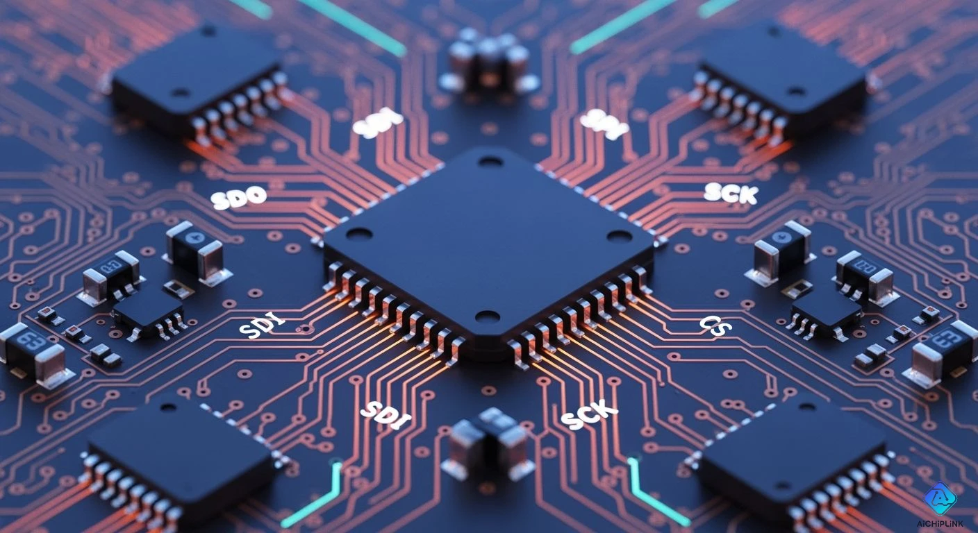
You need good hardware for modern embedded system designs. Powerful microcontrollers like the STM32H7 and ESP32 run modern systems well. Pairing your microcontroller with the Best SPI Interface IC gives high efficiency. You get fast data transfer over 10 MHz. Use Quad-SPI or Octal-SPI setups for this. Direct Memory Access (DMA) helps the CPU. It handles data tasks for the main chip. This tool allows real full-duplex communication now. It also lowers your overall system latency.
💡 Key Design Tip: Pick your spi communication ics using four main metrics: bus throughput, power efficiency, DMA integration, and pin count savings.
Fast memory chips use the spi protocol often. Precise analog converters also rely on this setup. Modern designs need fast data movement today. They must not waste your board space. Learn these SPI parameters to improve your project!
Key Takeaways
-
SPI protocol gives fast full-duplex communication over 10 MHz. It helps modern embedded systems.
-
Microcontrollers like STM32H7 and ESP32 use Quad-SPI. They also use Octal-SPI to speed up data transfers.
-
Direct Memory Access moves data transfer work away from the main CPU. This helps lower system latency.
-
Engineers pick SPI interface ICs based on bus throughput. They also look at power efficiency and saving pins.
-
Good PCB layouts need short traces and termination resistors. They keep signal integrity strong at high clock speeds.
SPI Protocol Performance Metrics in 2026
Clock Speed and Bus Throughput
New hardware needs top bus speed. You pick communication protocols for quick data work. Testing i2c vs spi shows big operational changes. Basic i2c is slow. The spi protocol hits clock speed over 10 MHz. You get full-duplex communication with spi hardware. New spi designs send data faster than basic i2c. You tune spi protocol settings for top speed.
Quad-SPI and Octal-SPI Modes
You want fast data transfer for outer flash memory. Advanced spi protocol modes boost data speeds with parallel lines. You reach big throughput for real-time communication tasks. Modern communication protocols give special choices for memory buses.
| Interface Mode | Data Rate Mode | Maximum Bandwidth |
|---|---|---|
| Quad-SPI (QSPI) | Single Data Rate (SDR) | Up to 200 Mbps |
| Quad-SPI (QSPI) | Double Data Rate (DDR) | Up to 400 Mbps |
| Octal-SPI (OSPI) | Single Data Rate (SDR) | Up to 400 Mbps |
| Octal-SPI (OSPI) | Double Data Rate (DDR) | Up to 800 Mbps |
DMA and Memory Interfacing
Direct Memory Access frees the CPU during big tasks. DMA handles spi communication streams well. You run fast full-duplex communication during main work. Engineers compare i2c vs spi for memory chips. SPI communication gives quick speeds for extra storage. You use full-duplex communication to speed memory work. It beats basic i2c buses.
Voltage Levels and Power Modes
New chips use changing voltage levels. You switch bus settings between 1.8V and 3.3V. Low-power microcontrollers save power while sleeping. When checking i2c vs spi, spi shows great efficiency. It works well in fast bursts. SPI communication saves battery power. Basic i2c uses more power for each byte. Fast spi lines use less. The spi protocol cuts protocol waste. You pick great communication protocols to boost system speed.
Top Microcontrollers for SPI Communication
New smart chips need fast data speed. The right chip changes system speed completely. You pick strong chips or cheap chips. These chips run the spi protocol fast. They also run it with great efficiency.
STM32 Family
STMicroelectronics makes strong chips for big jobs. The STM32 group leads in raw power. It also leads in fast bus speed. Start with simple boards for easy tasks. Or pick top models for hard jobs.
-
STM32F103C8T6: People call this chip "Blue Pill". You get basic spi speeds up to 18 MHz. It costs very little for small builds.
-
STM32C5 Series: This new line adds strong security features. It also uses very little power. You get fast spi communication without high power.
-
STM32H7 Series: This fast chip runs over 400 MHz. It uses QSPI and OSPI engines. These engines move your data very quickly.
⚡ Performance Note: The STM32H7 handles multi-channel spi setups well. It uses smart hardware DMA for this. You save CPU power during big files.
Espressif ESP32 Series
Espressif changed chip design with wireless tech. It adds fast wired communication protocols too. The ESP32 family has many spi controllers inside. Send data over Wi-Fi or Bluetooth fast. Read extra sensors at the same time.
The ESP32-S3 and ESP32-C6 use Octal-SPI lines. Hook up fast RAM with fewer wires. Hook up flash storage easily as well. Engineers test i2c vs spi on this chip. SPI beats i2c in real top speed. Use i2c for small easy sensors. Pick spi for screens and camera units.
ESP32 Master Config ---> [ SPI Bus: MOSI, MISO, SCK, CS ] ---> SPI Display / Memory
Raspberry Pi RP2040 and Microchip MCUs
You build cheap products with basic chips. These chips give stable spi communication daily.
-
Raspberry Pi RP2040: This chip has two spi units. It also has special PIO blocks inside. Build custom communication protocols with ease. Or make extra spi channels quickly.
-
ATmega328P: This is an old 8-bit chip. It has very simple control registers inside. Learn basic spi ideas on this board.
-
Microchip PIC16 Series: These low-cost chips fit small boards. They read basic sensors with top trust.
Pick communication protocols based on your speed needs. SPI moves data faster than i2c here.
Essential SPI Communication ICs for 2026
Selecting the Best SPI Interface IC
Pick a top chip for your goal. Modern systems need good communication protocols. They send data between chips quickly. Check speed, power, and pin count first. Basic i2c runs slow during heavy tasks. Testing i2c vs spi helps you pick well. The spi protocol gives you top speed.
| Selection Parameter | SPI Protocol | I2C Protocol | UART Protocol |
|---|---|---|---|
| Hardware Lines Required | 4 pins (MOSI, MISO, Clock, Select) | 2 pins (Data, Clock) | 2 pins (TX, RX) |
| Data Transfer Rate | Highest (reaches ~10 to 60 Mbps) | Moderate (up to 3.4 Mbps) | Lowest (typically up to 115.2 kbps, max ~1 Mbps) |
| Addressing / Topography | Dedicated Hardware Select lines per slave | Shared bus using 7/10-bit software addresses | Point-to-point (single master to single slave) |
| Data Flow Mode | Simultaneous Bidirectional (Full-Duplex) | Single-direction at a time (Half-Duplex) | Asynchronous Full-Duplex or Half-Duplex |
| Relative Power Usage | Higher (driven by high clock frequencies) | Moderate (influenced by pull-up resistors) | Low (minimal active clocking requirement) |
Think about key trade-offs before buying:
-
Pin Efficiency vs. Hardware Complexity: SPI needs separate selection wires for every chip. This layout increases board trace routing complexity. I2C uses two shared wires for all devices. However, it demands extra pull-up resistors.
-
Power Demands: Fast spi clocks consume energy very quickly. I2C draw relies on resistor values instead. UART stays quiet during idle wait times.
-
Distance and Signal Integrity: SPI and i2c suit short board connections. Long wires create signal noise and loss. UART travels farther but runs much slower.
Fast systems need quick data movement. Picking the best spi interface ic boosts overall work efficiency.
GPIO Expanders, Switches, and Multiplexers
Adding extra chips uses board pins fast. SPI needs a direct wire per slave. This rule limits your total sensor count. You can use small decoders instead. A logic chip uses simple selection lines. It opens one target device at once. Three pins can run eight outer devices. This trick saves pins with low delay.
Standard i2c buses run at fixed speeds. Smart spi communication ics fix routing problems easily. The MCP23S17 chip adds extra input pins. It handles fast signals better than i2c. Comparing i2c vs spi shows real speed wins. SPI gives lower delay for button clicks. Use spi switches to route data safely. Faster spi communication keeps system responses quick. The best spi interface ic saves your main chip pins. Modern spi communication builds keep circuit boards clean.
External Flash and Memory Storage
External flash memory stores cheap extra data. Winbond W25Q chips deliver files very quickly. They hold big images and system logs. Use Quad-SPI to double your reading speed.
💡 Storage Tip: External flash memory chips allow systems to log data rapidly while keeping board space small.
These memory units save main processor space. New spi communication ics make storage work easy. Fast clock rates give instant data access. So, spi communication brings great reliability to software developers. You get dependable spi communication for hard jobs. Write logs and read files without errors. Fast spi chips keep system operations running smoothly.
Precision ADCs, DACs, and Ethernet Controllers
Analog tools need precise timing to work. The TI ADS1118 reads accurate sensor voltages. It uses the spi protocol to send readings. Converters need quiet lines with zero noise. Testing i2c vs spi shows timing wins. A steady spi clock prevents data timing mistakes. Thus, medical tools rely on these chips.
Network controllers use fast lines for traffic. Chips like W5500 link boards to networks. The WIZnet chip runs network tasks alone.
| Feature / Aspect | WIZnet W5500 Controller | Software-Based Controllers |
|---|---|---|
| TCP/IP Processing | Integrated hardwired protocol engine | Executed via software stack on host MCU |
| Host MCU Overhead | Significantly reduced processing burden | High CPU resource and memory usage |
| Supported Protocols | On-chip hardware support for TCP, UDP, IPv4, ICMP, ARP, IGMP, PPPoE | Requires manual software implementation per protocol |
| Development Complexity | Low; eliminates software protocol stack development | High; requires complex network stack integration |
The hardwired W5500 cuts chip processor load. Send packet data fast with steady performance. Pick the best spi interface ic for networks. Using spi communication ics simplifies basic hardware setups. Good spi communication ensures quick overall system response. Engineers trust these communication protocols for top bus speed. Using spi yields strong stability, making i2c unnecessary for fast tasks where i2c fails.
PCB Layout and Signal Integrity for SPI
Good board layouts ensure reliable communication. Fast signals create unwanted noise. Careful trace routing preserves signal quality. Good circuit design keeps signals clean.
Impedance Matching and Termination
High clock frequencies demand clean trace routing. Fast edge rates cause signal reflections. Place series termination resistors near driver pins. These small resistors match trace impedance. Proper matching prevents voltage overshoot. This step guarantees reliable data transfer. High clock speed settings require protection. Fast clock speed requires sharp edges.
💡 Layout Tip: Place a 22-ohm to 33-ohm resistor close to the spi clock output pin to stop ringing.
Trace Capacitance and Propagation Delay
Long traces act like unwanted capacitors. High trace capacitance slows clock pulses. Keep all spi lines very short. Match MOSI, MISO, and clock trace lengths. Equal trace lengths prevent timing skew. Long lines delay transfer rates significantly. Smart trace placement improves overall design.
Ground Planes and Decoupling Strategy
Route spi lines over solid ground planes. A continuous plane provides clear return paths. Fast signals shift data accurately. Avoid running traces across split ground regions. Interrupting ground paths creates severe noise. Place decoupling capacitors next to power pins. Clean power delivery boosts board performance. Reliable data lines prevent signal loss.
| Component / Technique | Recommended Placement | Primary Benefit |
|---|---|---|
| Termination Resistor | Right next to spi master pin | Eliminates signal ringing |
| Decoupling Capacitor | Adjacent to IC power pins | Stabilizes operational voltage |
| Solid Ground Plane | Directly under spi trace layer | Reduces overall signal noise |
Solid setups ensure top spi performance. Run spi buses at maximum clock frequency. The spi protocol demands stable signal lines. Modern devices move data without errors.
Multi-Slave Bus Architecture and Arbitration
Linking many chips needs smart wire layouts. You hook many slaves to one master easily.
Chip Select Logic Management
You control devices using separate Chip Select pins. Stop bus conflicts on shared spi buses. Give individual Chip Select lines to each slave unit. Turn on one Chip Select line at once. This step ensures safe, reliable data transfer. It also stops ugly signal collisions completely. This setup keeps spi communication running smoothly.
Comparing i2c and spi shows big differences. An i2c setup sends addresses over two wires. Yet i2c speed drops with extra sensors. Dedicated select wires in the spi protocol maintain top speed. An i2c setup needs resistors on both wires.
Clock Polarity and Phase Settings
Master and slave chips must match timing modes. Set Clock Polarity and Phase inside control registers.
Mode 0: CPOL=0, CPHA=0  |  Mode 1: CPOL=0, CPHA=1
Mode 2: CPOL=1, CPHA=0  |  Mode 3: CPOL=1, CPHA=1
Four modes control exact data sampling timing. Bad settings break your data streams quickly. Match timing modes to gain fast data movement. Fast chips use full-duplex communication to swap data. Every protocol needs correct clock settings.
| Parameter | SPI Standard | I2C Standard |
|---|---|---|
| Bus Speed | Fast data rates | Slower byte transfer rates |
| Data Lines | Separate lines | Single shared line |
Preventing Bus Contention and Cross-Talk
Fast signal lines generate unwanted trace noise. Route ground traces beside clock lines. This layout blocks bad trace cross-talk. Parallel lines cause signal bleed during transfers.
Pick your communication protocols with great care. An i2c bus uses open-drain lines. Long i2c lines suffer from slow rise times. Instead, spi uses push-pull outputs for quick edges.
💡 Design Tip: Keep clock traces short and surround them with ground copper to protect sensitive signals.
Busy boards run solid full-duplex communication. Clean trace layouts boost spi communication stability. Use the right spi protocol setup for top speed. Pick spi for quick sensor reads today. Use i2c for slow, basic system tasks instead. Good spi layout choices guarantee rapid data work. Smart chip setups improve your spi communication project.
Good chips help you build fast embedded systems. Pick your microcontrollers and spi communication ics with care. Match these parts to your main project needs.
| Requirement | Recommended Component |
|---|---|
| Maximum Data Speed | STM32H7 Chip |
| Pin Count Efficiency | MCP23S17 Expander |
Pick the best spi interface ic for speed. It boosts your spi bus speed quickly. Keep all trace lines very short during spi routing. Place termination resistors close to driver pins. This step protects overall signal quality well. Smart spi design keeps data transfers clean. Your embedded hardware runs without mistakes now.

Written by Jack Elliott from AIChipLink.
AIChipLink, one of the fastest-growing global independent electronic components distributors in the world, offers millions of products from thousands of manufacturers, and many of our in-stock parts is available to ship same day.
We mainly source and distribute integrated circuit (IC) products of brands such as Broadcom, Microchip, Texas Instruments, Infineon, NXP, Analog Devices, Qualcomm, Intel, etc., which are widely used in communication & network, telecom, industrial control, new energy and automotive electronics.
Empowered by AI, Linked to the Future. Get started on AIChipLink and submit your RFQ online today!
Frequently Asked Questions
How do you evaluate i2c vs spi for real-time applications?
Pick parts based on required speed. The spi protocol moves data very fast. It uses four physical wires. In i2c vs spi tests, spi hits top speeds. It relies on full-duplex communication. An i2c bus uses two shared lines. An i2c setup runs slower than spi.
Why do engineers use two-way data streaming in embedded designs?
Engineers pick full-duplex communication for data. It sends data both ways at once. This path doubles your total bus throughput. Fast spi chips need this feature. Standard i2c devices run in half-duplex mode. An i2c master stops during read steps.
How many pins do you need for an i2c bus versus spi?
An i2c bus uses two signal wires. You link many i2c devices easily. An i2c layout saves board space. An spi bus needs four main wires. Yet spi gives much higher bandwidth.
Which communication protocols suit high-speed flash memory best?
Big memory needs modern communication protocols like Quad-SPI. These ports move large data files fast. You stream audio and video smoothly. An i2c port lacks fast clock speeds. Use an i2c line for small sensors.