Best Current & Voltage Sensors for Microcontrollers
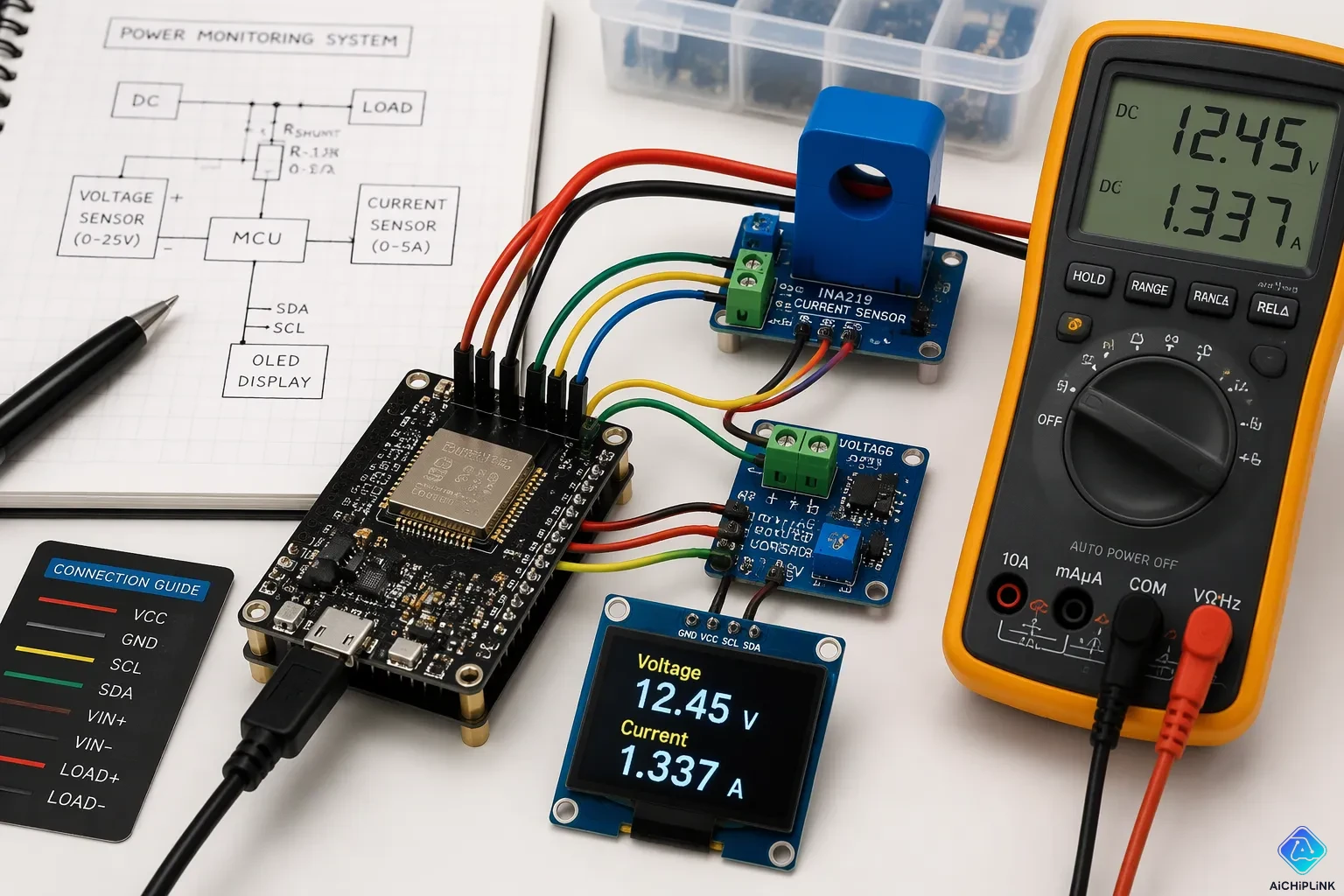
Shunt-based ICs, Hall-effect sensors, and dedicated current/voltage monitor ICs are the top choices for microcontroller applications. Shunt-based designs give high precision on low-voltage rails. Hall-effect parts provide built-in isolation for high-current and motor work. Monitor ICs combine sensing, amplification, and a digital interface for compact telemetry.
Engineers weigh accuracy against isolation, cost, and simplicity. No single category wins on every front. This post compares the Best Current & Voltage Sensors and maps each option to real use cases. Readers can then match a part to their project quickly.
Key Takeaways
-
Shunt-based sensors are very accurate for low-voltage rails and battery monitoring.
-
Hall-effect sensors come with built-in isolation for high-current and motor control uses.
-
Current transformers work well for measuring AC mains power and watching energy use.
-
Special monitor chips handle both sensing and digital output, which makes them great for small telemetry setups.
-
Pick a sensor based on how accurate it needs to be, whether it needs isolation, its cost, and how much board space you have.
Best Current & Voltage Sensors Compared
Key Specs Side by Side
A side-by-side view helps engineers make a shortlist of the Best Current & Voltage Sensors before they read datasheets. The table below covers the main categories, their typical ranges, interfaces, isolation behavior, accuracy profile, and cost tier. Each row shows where an option fits best instead of naming a winner.
| Sensor type | Typical range | Interface | Isolation | Accuracy | Cost tier |
|---|---|---|---|---|---|
| Shunt-based IC (e.g., MAX4080) | Milliamps to tens of amps | Analog voltage | None inherent | High with a 4-wire shunt | Low to moderate |
| Hall-effect module (e.g., ACS712) | Roughly 5 A to 60 A | Analog voltage | Inherent, rating varies | Moderate; offset drift is the main concern | Low |
| Current transformer | AC mains currents | Analog (AC output) | Inherent | Good for AC only | Moderate |
| Voltage divider | Scaled rail voltage | Analog voltage | None | Depends on resistor tolerance | Very low |
| Dedicated monitor IC (e.g., ADE9153A) | System-level rails | I2C or SPI | Varies by part | High, factory calibrated | Moderate to high |
Common modules cover about 5 A to 60 A. The KR Sense 90A sensor costs around $21.50 and is a high-current example for designs that need more headroom. Flux.ai notes that shunt resistors work well for cost-sensitive DC or AC measurements when a small voltage drop is okay. Hall-effect parts can provide galvanic isolation, depending on how they are built and rated.
Quick Picks by Use Case
For precision on a low-voltage rail, use a shunt plus a current-sense amplifier. Battery monitoring with tight board space is best with a low-power monitor IC. Isolated high-current work, like motor drive, points to Hall-effect sensors. AC mains metering needs a current transformer or an isolated voltage module.
One warning applies to Hall parts. An EEVblog forum contributor says:
ACSxxx sensors aren't actually very good - you'll probably get within your few% though. Zero drift will be your #1 problem to solve with anything hall based. ... I would definitely look at using shunt resistors rather than hall sensors if you want a reliable ZERO.
That trade-off matters for designs that measure near zero current. Allegro explains that integrated sensors keep the smallest footprint and come factory calibrated. Coreless parts handle 100 A to 4000+ A with no core saturation. The Best Current & Voltage Sensors therefore split along current level, isolation need, and precision target. A shortlist built from this table narrows the field to two or three candidates for a full datasheet review.
Shunt-Based Current Sensors
How They Work
A shunt resistor turns load current into a small voltage drop. STMicroelectronics explains the idea using Ohm's law: current through the shunt makes a voltage called VSENSE, kept small to limit power loss. A current-sense amplifier then boosts that tiny signal with an internal instrumentation amplifier. The output voltage matches the load current and goes to an ADC pin on the microcontroller.
STMicroelectronics describes the part in simple terms:
A current sense amplifier is a differential amplifier providing an analog output voltage proportional to the current flowing into a load connected on its input.
The MAX4080 is a common example for Arduino, ESP32, and ESP8266 projects. It handles currents from a few milliamperes to several hundred amperes and supports real-time measurement in several topologies. It also uses an integrated matched resistive gain network for precise gain. Its built-in gain resistors shrink the PCB footprint too, and its input common-mode range reaches far past the supply rail.
Pros, Cons, and Best Uses
Many engineers see the shunt as the best current sensor for precision work. Passive Components notes that shunt resistors give highly accurate sensing when paired with precision ADCs or instrumentation amplifiers. They cost little, take up little space, and work from microampere measurements up to high-current industrial loads. A 4-wire (Kelvin) shunt gives the most accurate result, since it keeps the current path apart from the sense leads.
Problems show up when the application needs isolation. Very high voltages, galvanic isolation between measurement and power domains, strong EMI, and extremely high currents all push designs toward other options. Allegro MicroSystems points out that an isolated shunt setup needs an external isolated amplifier plus a dedicated isolated bias supply, which raises BOM cost and board area. Shunt I²R losses also make heat. These are trade-offs, not flaws: the shunt stays the precision leader wherever isolation is not needed.
Hall-Effect Current Sensors
How They Work
A Hall-effect sensor measures current without touching the wire. Current flowing through a copper path makes a magnetic field. The sensor turns that field into a voltage that matches the current. Aim Dynamics explains the science behind it: the Lorentz force creates a voltage difference when magnetic field lines cross the current at a 90-degree angle. The Hall voltage that results gets bigger as the field gets stronger.
The ACS712 is the usual example for AC and DC measurement in embedded systems. Microcontrollers Lab reports that the chip pairs a linear Hall circuit with an internal copper path, and the two are fully isolated. Three versions cover ±5 A, ±20 A, and ±30 A, with sensitivities of 185 mV/A, 100 mV/A, and 66 mV/A. Allegro MicroSystems notes that many designs focus the field with a slotted toroid, and the induced flux grows with the number of turns.
Reading the output takes care. A 10-bit ADC resolves only about 5 mV per step, so the low-sensitivity 30 A version has more quantization error than the 5 A part. The output sits at half the supply, about 2.5 V on a 5 V rail, so firmware must zero the reading when no current flows and subtract that offset.
Pros, Cons, and Best Uses
Built-in isolation is the main plus. The current path never touches the signal path, which works well for motor control, high-current rails, and any load that must stay electrically separate from the MCU. The ACS712 also shows current polarity, so one part handles bidirectional DC.
Accuracy is the weak spot. TI's precision hub calls Hall sensors naturally noisy, with output that changes a lot with temperature. Knick International adds that nearby conductors and sensor position make total error hard to judge. The ACS712 datasheet lists 1.5% total output error at 25°C, and that number grows outside a controlled bench. Open-loop parts work fine for monitoring tasks; closed-loop modules cost more and give better accuracy. Designs that need a reliable zero should look at shunts instead.
Current Transformers
How They Work
A current transformer (CT) measures AC current using electromagnetic induction. AC current in the primary winding causes a matching current in the secondary. That secondary current flows through a terminating resistor and makes a voltage you can measure. Passive Components explains that the output follows the primary current directly.
The design only reacts to changing magnetic flux. A DC component never shows up in the secondary signal, but it still pushes the core. If the core is not reset properly each cycle, it can saturate. PatSnap states the limitation plainly:
They are not suitable for DC current measurements, limiting their application range.
The PMC literature adds a practical warning:
Instrument current transformers (CTs) measure AC currents. The DC component in the measured current can saturate the transformer and cause gross error.
Pros, Cons, and Best Uses
CTs work great for AC mains and power-monitoring jobs that need isolation. The primary conductor never touches the measurement circuit, so the MCU stays electrically separate from the line. Engineers use them for utility submetering, smart meters, and panel-level energy monitoring. The Alibaba buying guide sorts the common forms by fit:
| CT type | Pros | Cons | Best uses |
|---|---|---|---|
| Solid-core | Best linearity, lowest phase error, high insulation rating | Needs wire disconnection to install | Permanent installations needing long-term stability |
| Split-core | No wiring interruption, fast deployment | Slightly higher ratio error, hinge wear | Live-panel upgrades and audits |
| PCB-mount | Minimal footprint, assembly-friendly | Very low isolation, limited current range | High-volume OEM designs with tight space |
Accuracy classes follow IEC 61869-2 and IEEE C57.13. Class 0.5 stays within ±0.50% from 1% to 120% of rated current, according to Weisho Elec. Metering work often uses class 0.2 or 0.5. Protection relays may accept class 1.0 or 5.0. A CT is a good fit for AC mains metering. It is not a good fit for DC rails or very distorted waveforms unless you add extra conditioning.
Voltage Sensors for MCUs
Dividers and Monitor ICs
A resistive voltage divider is the easiest way to sense voltage with a microcontroller. Two resistors scale a high voltage down to the ADC input range, usually 0 to 3.3 V or 0 to 5 V. Industrial Monitor Direct notes that this method works well for sinusoidal AC signals and gives real-time waveform sampling. The division follows a simple relation: Vadc = Vac_rms × √2 × (R2 / (R1 + R2)). The divider is low cost and uses few parts. It gives no isolation, so the MCU shares a ground reference with the measured line.
The ZMPT101B is the common module for AC voltage sensing in embedded projects. It packs a small transformer with an op-amp stage and gives an isolated analog output. The ADE9153A, sold on an Adafruit breakout board, targets reliable AC voltage measurement with evaluation support. Industrial Monitor Direct also lists dedicated metering ICs for higher accuracy: the Analog Devices ADE7912 and ADE7953 with SPI, the Microchip MCP3909, and the Texas Instruments ADS131M04. These parts suit designs that need calibrated results and isolation.
Pros, Cons, and Best Uses
Sensor outputs come in two forms. A voltage-varying output changes its amplitude directly with the measured signal. A current-varying output drives a current that a burden resistor turns into a voltage. Current-varying outputs resist lead resistance and noise pickup better, so they tend to give more reliable readings over long cable runs. Voltage-varying outputs are simpler to wire but more sensitive to interference.
Dividers fit DC rail monitoring, battery voltage checks, and low-cost projects where isolation is not needed. The ZMPT101B suits AC mains sensing in hobby and prototype work. The ADE9153A and the metering ICs fit energy monitoring and power-quality products that need accuracy and a digital interface. Each option trades simplicity against isolation and precision, and the application decides which trade matters most.
Dedicated Monitor ICs
How They Work
A dedicated monitor IC puts the whole measuring setup into one package. It senses current through a shunt resistor and reads the load supply voltage at the same time. On-chip amplifiers and high-resolution ADCs then turn those signals into digital values. STMicroelectronics reports that its monitor family includes ADCs up to 16 bits and reports current, voltage, power, temperature, and alerts. The host microcontroller reads the results over a digital bus instead of sampling analog pins.
The interface choice shapes the design. Allegro MicroSystems application note AN296180 describes I2C and SPI interfaces on the ACS71020 and ACS37800 power monitoring ICs. STMicroelectronics offers standard I2C on the TSC1214 at rates up to 400 kHz and a MIPI I3C interface on the TSC1641 at rates up to 12.5 MHz. Both parts fit 3x3mm footprints and handle voltages up to 60 V. An ALERT pin flags out-of-range conditions, and internal registers let firmware set low and high thresholds.
Pros, Cons, and Best Uses
Integration brings clear gains. One part replaces a shunt amplifier, an ADC channel, and several passive parts, which saves pins and board space. Factory calibration and digital output remove analog noise concerns at the MCU. Texas Instruments lists the strengths of its battery monitor ICs: support for 3-series to 16-series cells in a small solution size, a protection suite covering voltage, temperature, current, and internal diagnostics, and flexible links such as 400-kHz I2C, SPI, and a one-wire HDQ interface.
The trade-offs are cost and flexibility. A monitor IC costs more than a bare shunt and amplifier, and the fixed digital interface limits how the designer routes signals. Texas Instruments positions these parts for battery backup units, cordless power tools, vacuum cleaners, robots, and e-bikes. Power monitoring and battery management reward the integrated approach whenever telemetry and a small footprint matter most.
Selection Criteria
Accuracy, Resolution, and Interface
Accuracy begins with the ADC inside the microcontroller. A 12-bit converter on a 3.3 V rail resolves about 0.8 mV per step, which maps to roughly 8 µA of current resolution in a typical sense circuit, according to Data Capture Control. Designers can tighten that figure by narrowing the ADC range with a reference voltage or by adding an external converter. The ADS1115 offers higher bit resolution, a built-in voltage reference, and programmable gain, and it talks over I2C.
Resolution also depends on the sensor network around the ADC. Data Capture Control notes that lowering the load resistor from 2.36 V to 1.30 V of swing costs resolution, moving from 8 µA to 80 µA. Averaging helps, but Texas Instruments reports that maximum averaging leaves only about 3.5 samples per second for the host. Interface choice follows the same logic. A part with I2C or SPI frees analog pins for other duties, while an analog output demands a dedicated ADC channel.
Isolation, Power, and Cost
Isolation reshapes the shortlist fast. Wevolver lists shunt-plus-amplifier designs at ±3–5% accuracy with no inherent galvanic isolation, open-loop Hall parts at ±2–10% with isolation, and closed-loop Hall parts at ±0.4–0.7% at higher cost and power draw. Integrated isolation families such as iCoupler couple power across the barrier and remove the need for a separate supply on each side, per AllPCB.
Power and cost close the loop. A shunt dissipates heat through the resistor, and a PCB trace used as a shunt carries a 3900 ppm temperature coefficient, according to an EEVblog forum contributor. Board space and supply budget therefore push compact designs toward monitor ICs and push high-voltage designs toward isolated parts. No criterion wins alone; each one shifts the best fit.
Application Examples
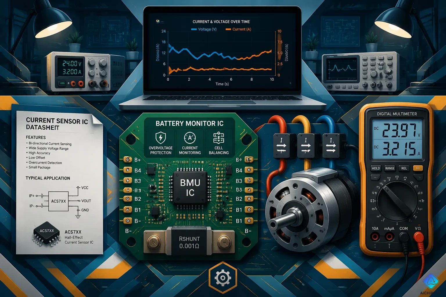
Battery-Powered Devices and Power Management
Battery-powered products need close current and voltage tracking. Shunt-based sensors give the precision these designs need. A low-value shunt plus a current-sense amplifier measures charge and discharge current with very little loss. Dedicated monitor ICs do even more. They put the shunt interface, amplification, and a digital bus into one package. Firmware then reads current, voltage, and temperature over I2C or SPI without using up analog pins.
Power monitoring and battery management are among the most common uses for these parts. A battery monitor IC checks cell voltage and pack current at the same time. It can signal overcurrent or overtemperature through an alert pin. Portable tools, robots, and e-bikes all depend on this setup, as Texas Instruments notes in its battery monitor documentation. The small footprint matters here, because the sensor sits on the same board as the protection circuit.
Motor Control and Power Supplies
Motor drives and power supplies need sensors that handle high currents and keep the control side safe. PowerUC sorts the options by job. Voltage sensors detect the DC bus voltage and the motor phase voltage in frequency converters and servo systems. Current sensors handle motor current monitoring, load detection, ground fault protection, and energy metering. Hall-effect parts measure both DC and AC current and provide electrical isolation. Rogowski coils work well for large and high-frequency currents, with no magnetic saturation and a wide frequency response.
| Sensor type | Role in motor control and power supplies | Key characteristic |
|---|---|---|
| Voltage sensor | DC bus and phase voltage sensing, output monitoring | Enables precise control |
| Current sensor | Motor and load current, ground fault, energy metering | Broad monitoring role |
| Hall-effect current sensor | Wide current range, high-precision measurement | DC and AC, with isolation |
| Hall-effect voltage sensor | High-voltage isolated circuits, motor drives, EVs | High isolation |
| Rogowski coil | Large and high-frequency currents | No saturation, wide bandwidth |
Tractian adds a useful point. Voltage sensors mounted at the motor control center or terminal box catch supply changes before they cause heat damage. Hall-effect voltage sensors get voltage indirectly from the magnetic field of current flow, which fits high-voltage isolated circuits. These examples show that current and voltage sensors serve power monitoring and battery management in both low-voltage and high-power designs.
Shunt-based ICs suit precision work on low-voltage rails. Hall-effect sensors fit isolated high-current jobs. Current transformers serve AC mains metering. Monitor ICs deliver integrated telemetry for battery and power systems.
A short checklist speeds the decision:
-
Check the ADC resolution and available pins.
-
Confirm whether the load needs isolation.
-
Compare the supply budget and board space.
-
Weigh cost against the accuracy target.
The best choice depends on the application. Readers can revisit the comparison table to shortlist the Best Current & Voltage Sensors for their next design.

Written by Jack Elliott from AIChipLink.
AIChipLink, one of the fastest-growing global independent electronic components distributors in the world, offers millions of products from thousands of manufacturers, and many of our in-stock parts is available to ship same day.
We mainly source and distribute integrated circuit (IC) products of brands such as Broadcom, Microchip, Texas Instruments, Infineon, NXP, Analog Devices, Qualcomm, Intel, etc., which are widely used in communication & network, telecom, industrial control, new energy and automotive electronics.
Empowered by AI, Linked to the Future. Get started on AIChipLink and submit your RFQ online today!
Frequently Asked Questions
Which sensor type gives the best accuracy for low-voltage rails?
A shunt resistor with a current-sense amplifier gives the highest precision. The MAX4080 is a popular pick for Arduino, ESP32, and ESP8266 designs. A 4-wire (Kelvin) shunt keeps the sense leads away from the current path and makes the result even better. This setup works for rails that do not need galvanic isolation.
When does a design need an isolated current sensor?
Isolation matters when the measuring circuit must stay electrically separate from the load. Motor drives, high-current rails, and AC mains work all belong in this group. Hall-effect parts like the ACS712 give built-in isolation. Current transformers do the same for AC lines. Shunt designs need extra isolation hardware in these cases.
Can a Hall-effect sensor measure near zero current reliably?
Zero drift is the biggest weakness of Hall-based parts. The ACS712 lists 1.5% total output error at 25°C, and that number grows outside a controlled bench. Firmware must zero the output while no current flows. Designs that need a trustworthy zero reading should use a shunt instead.
How does ADC resolution affect sensor choice?
A 10-bit ADC resolves only about 5 mV per step. That step size adds quantization error to low-sensitivity Hall outputs. A 12-bit converter on a 3.3 V rail resolves roughly 0.8 mV per step. Higher resolution or an external converter such as the ADS1115 tightens the measurement and widens the usable sensor range.
What options exist for currents above 60 A?
Common modules cover roughly 5 A to 60 A. The KR Sense 90A sensor costs around $21.50 and adds headroom for higher-current designs. Coreless Hall parts handle far larger currents with no core saturation. Shunt-based designs also scale up when the resistor and amplifier are rated for the load.