The ULN2003 stepper motor driver helps you move a stepper motor. It does this by controlling the electric signals sent to the coils. Many people use this driver with the 28BYJ-48 stepper motor. It is popular in school projects and simple robots. You often see this driver in hands-on learning. This is because it can handle more current and voltage.
-
You can find the stepper motor driver in learning kits and DIY projects.
-
Beginners and hobbyists like to use this for robots and automation.
If you know the pinout, sequence, and how the driver works, you can connect and use your stepper motor safely and easily.
Key Takeaways
-
The ULN2003 stepper motor driver sends signals to the motor coils. This helps control stepper motors in robots and automation projects.
-
Knowing the pinout is very important. It helps you connect the ULN2003 driver to your stepper motor the right way. This keeps things safe and working well.
-
The step sequence (IN1, IN3, IN2, IN4) helps the motor move smoothly. If you follow this order, you can control the motor’s direction and speed exactly.
-
There are different stepping modes like full-step and half-step. These change how the motor works. Pick the mode that fits your project’s need for power or smooth movement.
-
Always check your wiring and connections before turning on the power. This stops damage and makes sure your stepper motor works right.
ULN2003 Stepper Motor Driver Overview
What Is the ULN2003 Stepper Motor Driver
The ULN2003 stepper motor driver helps you control stepper motors. It sits between your microcontroller and the motor. The driver sends signals to move the motor in small steps. It can handle more current and voltage than a microcontroller. People often use it with the 28BYJ-48 stepper motor. The ULN2003 makes it simple to change the motor’s direction and speed. You can use this driver in many robot and automation projects.
Key Features
The ULN2003 driver is strong and has helpful features. You can see its main details in the table below:
| Feature | Specification |
|---|---|
| Maximum Driving Voltage | 50V |
| Maximum Current | 500mA |
| Input Voltage | 5V |
| Saturation Voltage Drop | ~1V |
| Breakdown Voltage (BVCEO) | ~36V |
| Current per Unit | 350mA |
| Package Type | Dual-row 16-pin |
| Integrated Freewheeling Diode | Yes |
-
The ULN2003A can handle up to 500mA of current.
-
Some stepper motors need as much as 600mA.
-
The module’s voltage rating is usually from 9V to 24V, based on your motor.
The module has freewheeling diodes built in. These help protect your circuit from voltage spikes. It uses a dual-row 16-pin package. This makes it easy to connect to your stepper motor and microcontroller.
Common Stepper Motor Applications
You can use the ULN2003 module in many projects. The table below lists some common uses:
| Application Type | Description |
|---|---|
| Driving Stepper Motors | The ULN2003 is often used to drive 4-phase (unipolar) 5-wire stepper motors. These motors are common in robots for precise movement. |
| Boosting Arduino Outputs | It can boost Arduino output from 40mA to 500mA. This lets you control bigger devices like relays, which are used in automation. |
You will find this module in robots, 3D printers, and automatic doors. The module helps you move things exactly how you want. It can also boost the output of your Arduino or other microcontrollers. This makes the ULN2003 driver a good choice for learning about stepper motors and drivers.
ULN2003 Driver Pinout
Understanding the pinout of the ULN2003 stepper motor driver helps you connect your stepper motor correctly. The pinout shows you where to attach each wire. If you follow the pinout, you can avoid mistakes and protect your components.
Pinout Diagram and Table
You can see the pinout of the ULN2003 driver in the table below. This table helps you find each pin’s function. The pinout diagram on most boards also shows these labels.
| Pin Number | Function Description |
|---|---|
| Pin 1-7 | Input pins (Input1 to Input7) - Triggered by +5V |
| Pin 8 | Common ground pin - Provides ground reference voltage |
| Pin 9 | COM pin - Voltage test or suppressor pin (optional) |
| Pin 10-16 | Output pins (Output1 to Output7) - Connect to ground when input is high |
Most stepper motor projects use only four input pins: IN1, IN2, IN3, and IN4. These pins control the stepper motor coils. The output pins connect to the stepper motor wires. You will also see a 5-pin connector on the driver board. This connector makes the pin connections to the stepper motor easy.
Tip: Always check the pinout diagram printed on your ULN2003 driver board. This helps you match the pin numbers to the correct wires.
IN1, IN2, IN3, IN4 Functions
The IN1, IN2, IN3, and IN4 pins are the main control pins for the stepper motor. You connect these pins to your microcontroller, such as an Arduino or ESP32. Each pin controls one coil inside the motor. When you send a signal to one of these pins, the driver activates the matching coil.
| Pin | Function |
|---|---|
| IN1 | Drives the motor; connect to microcontroller output pin |
| IN2 | Drives the motor; connect to microcontroller output pin |
| IN3 | Drives the motor; connect to microcontroller output pin |
| IN4 | Drives the motor; connect to microcontroller output pin |
You can see how each pin matches a coil in the stepper motor pinout:
| Pin Name | Description |
|---|---|
| IN1 | Input for Coil A |
| IN2 | Input for Coil B |
| IN3 | Input for Coil C |
| IN4 | Input for Coil D |
When you send a signal to IN1, the driver powers Coil A. If you send a signal to IN2, the driver powers Coil B. You repeat this pattern for IN3 and IN4. This sequence lets you move the stepper motor one step at a time.
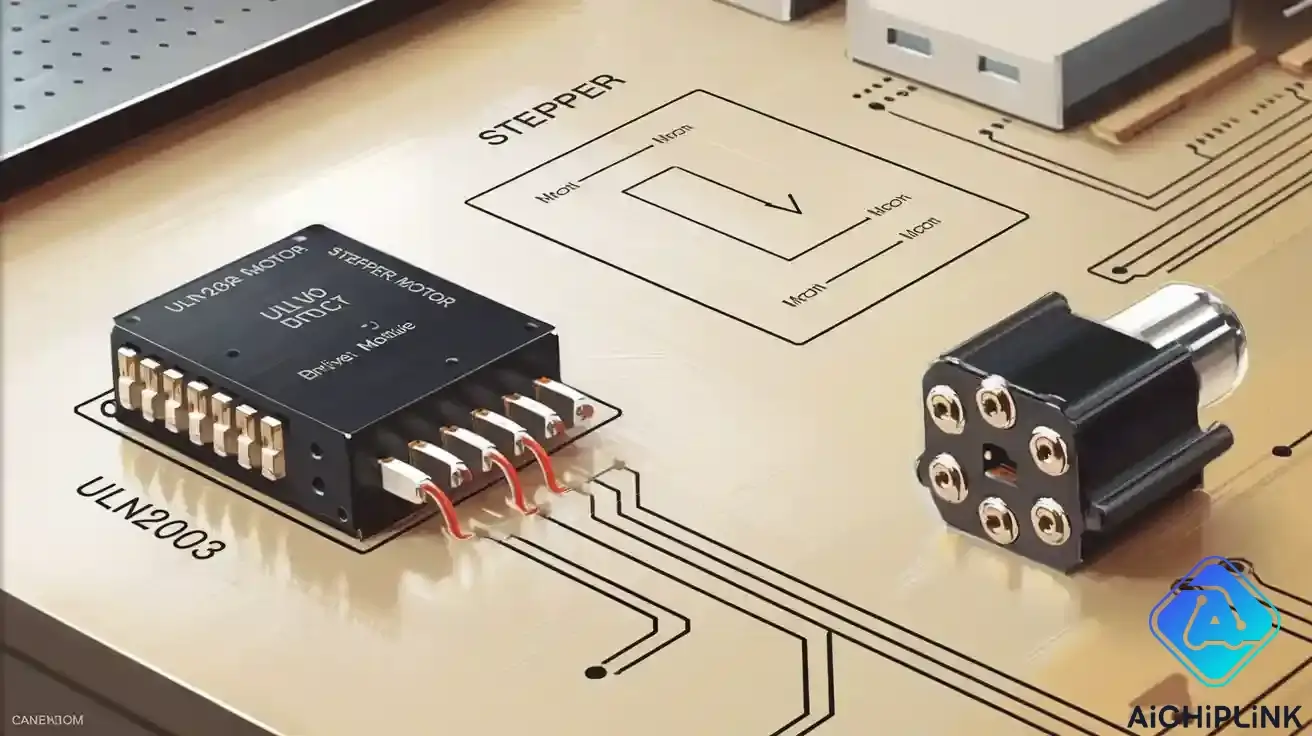
5-Pin Connector for Stepper Motor
The ULN2003 driver board has a white 5-pin connector. This connector makes it easy to attach the stepper motor. Each pin on this connector matches one wire from the stepper motor pinout. The wires go to the four coils and the common wire.
Here is how the 5-pin connector usually matches the stepper motor wires:
-
Pin 1: Coil A
-
Pin 2: Coil B
-
Pin 3: Coil C
-
Pin 4: Coil D
-
Pin 5: Common (VCC)
You plug the stepper motor cable into this connector. The driver board then sends signals to each coil through the correct pin connections. The pinout diagram on the board helps you match each wire to the right coil.
Note: Always double-check the stepper motor pinout before connecting. Wrong pin connections can stop the motor from working or cause damage.
The ULN2003 stepper motor driver makes wiring simple. You use the pinout diagram, connect IN1-IN4 to your microcontroller, and plug the stepper motor into the 5-pin connector. This setup lets you control the stepper motor with clear and safe pin connections.
Stepper Motor Sequence and Operation
Step Sequence (IN1-IN3-IN2-IN4)
The step sequence is very important for moving your stepper motor with the ULN2003 stepper motor driver. You must turn on the coils in a certain order to make the motor spin smoothly. For the 28BYJ-48 stepper motor, you use the IN1, IN3, IN2, and IN4 pins in this order:
-
IN1
-
IN3
-
IN2
-
IN4
You keep repeating these steps to turn the motor one way. If you do the steps backwards, the motor spins the other way. Each step turns on a different coil. This lets you pick the direction and speed of the stepper motor. If you skip or mix up the steps, the motor might shake, miss steps, or stop.
Tip: Always use the right step sequence when you write your microcontroller code. This helps your stepper motor run smoothly and work well.
How Does a Stepper Motor Work
You may ask, how does a stepper motor work? The idea is simple but useful. The stepper motor works by turning on coils in the stator one after another. When you send a signal to any IN1-IN4 pin, the ULN2003 driver turns on a coil inside the motor. This pulls the rotor to a new spot. By repeating the steps, you move the rotor in small, exact moves.
The way the stepper motor works lets you control its position very well. Each step moves the shaft by a set angle. You can count the steps to put the motor in the right spot. The step sequence also lets you pick which way the motor turns. If you want it to go backward, just do the steps in reverse.
-
The stepper motor moves in small steps.
-
Each coil turns on one after another to pick the turning direction.
-
The step sequence lets you control speed, direction, and position.
This way of working makes stepper motors great for jobs that need careful movement, like 3D printers or robot arms.
Stepping Modes
You can use different stepping modes to control your stepper motor. Each mode has its own step pattern and changes how the motor moves. The main stepping modes are full-step, half-step, and wave drive. The table below shows how they compare:
| Stepping Mode | Description | Pros | Cons | Applications |
|---|---|---|---|---|
| Full-step Drive | Moves one full step per pulse, energizing two coils simultaneously | Simple to use, gives most holding torque | Makes noise and shakes at low speeds, not as smooth | Industrial printers, CNC routers |
| Half-step Drive | Alternates between one and two coils energized, doubling positions | More steps, smoother turning | Torque is not even, a bit harder to use | 3D printers, medical devices |
| Wave Drive | Energizes one coil at a time, advancing the rotor step-by-step | Easiest to use, uses less power | Weakest torque, not smooth motion | Battery-powered tools, simple robots |
The stepping mode you pick changes the step pattern and how you control the motor. Full-step mode gives the most torque because two coils are on. Half-step mode gives more steps per turn, so you get smoother and finer moves. Wave drive uses less power but has the weakest torque.
-
Full-step mode gives the most torque.
-
Half-step mode gives more steps but less torque (about 70% of full-step torque).
-
You can add more current to the coil to help with torque loss in half-step mode.
Microstepping is a special way to control the motor. It splits each full step into smaller parts called microsteps. Microstepping makes the motor move smoother and shake less, especially at slow speeds. It helps the torque feel smoother and makes slow moves better. But it does not always make the motor more accurate because of how the motor is built. The step angle and number of steps per turn matter for how exact the motor is.
Note: Pick your stepping mode based on what your project needs. If you want more torque, use full-step mode. If you want smoother moves, try half-step or microstepping.
The step pattern, stepping mode, and control signals all work together. They help you use the ULN2003 driver to get the best from your stepper motor. By knowing how it works, you can control every step and make your projects move just right.
ULN2003 Driver Board Wiring
Connecting to 28BYJ-48 Stepper Motor
You can connect the ULN2003 driver board to the 28BYJ-48 stepper motor with just a few steps. The 5-pin connector on the driver board matches the motor’s cable. Plug the motor’s connector into the board. For the control signals, use these connections:
-
IN1 to Arduino digital pin 8
-
IN2 to Arduino digital pin 9
-
IN3 to Arduino digital pin 10
-
IN4 to Arduino digital pin 11
-
GND on the driver board to Arduino GND
-
VCC on the driver board to Arduino 5V
Tip: Always double-check your wiring before you power up the system. Incorrect wiring can cause the stepper to move in the wrong direction or not move at all.
Here are some common mistakes you should avoid:
| Mistake Description | Importance |
|---|---|
| Ensure the ground (E pin) connects to both the Arduino and the motor power supply. | A shared ground is crucial for stable signals. |
| Connect the COM pin to the motor’s positive supply. | This protects the circuit from voltage spikes using internal diodes. |
| Avoid adding resistors to the driver inputs. | Inputs should connect directly to controller outputs for proper functionality. |
| Use the ULN2003 only with unipolar stepper motors. | The driver is not compatible with bipolar motors. |
| Double-check IN1-IN4 wire connections. | Incorrect wiring can cause motor vibrations, skipped steps, or incorrect direction of movement. |
Interfacing with Arduino or Microcontroller
When you start interfacing stepper motor projects, follow these steps for the ULN2003 driver board:
-
Connect IN1, IN2, IN3, and IN4 on the driver board to Arduino digital pins 8, 9, 10, and 11.
-
Attach the GND pin of the driver board to Arduino GND.
-
Link the VCC pin of the driver board to Arduino 5V.
-
Plug the stepper motor into the 5-pin connector on the driver board.
-
Use an external power supply if your motor needs more than 5V or 80mA.
Note: For larger projects, always use a separate power supply for the motor. This keeps your Arduino safe from overload.
Power Supply and Testing
The recommended voltage supply for the ULN2003 driver board and 28BYJ-48 stepper motor is between 5V and 12V. The current supply should be up to 1 Amp. You should use a separate power supply or battery pack instead of powering the motor directly from the Arduino.
To test your wiring and the ULN2003 driver board:
-
Apply a positive voltage to each input pin (IN1-IN4) and check if the motor steps.
-
Use an LED with a 1K resistor on the output pins to see if the driver board switches correctly.
-
Connect a load to the output pin and a power source to test the driver board’s ability to drive loads.
Tip: Testing each input pin helps you find wiring mistakes before running your full program.
Practical Use and Troubleshooting
Example Code for Stepper Motor Control
You can try out the ULN2003 driver with the 28BYJ-48 stepper motor by using some easy code. Many guides show how to use the Arduino Stepper library for simple stepper motor control. Here is a sample code you can use to begin:
//Includes the Arduino Stepper Library
#include <Stepper.h>

// Defines the number of steps per rotation
const int stepsPerRevolution = 2048;

// Creates an instance of stepper class
// Pins entered in sequence IN1-IN3-IN2-IN4 for proper step sequence
Stepper myStepper = Stepper(stepsPerRevolution, 8, 10, 9, 11);

void setup() {
// Nothing to do (Stepper Library sets pins as outputs)
}

void loop() {
// Rotate CW slowly at 5 RPM
myStepper.setSpeed(5);
myStepper.step(stepsPerRevolution);
delay(1000);

// Rotate CCW quickly at 10 RPM
myStepper.setSpeed(10);
myStepper.step(-stepsPerRevolution);
delay(1000);
}
This code helps you use the Stepper library and set the pins in the right order. You can find more guides online that show how to use this code for your own projects.
Step-by-Step Operation
If you want to use the ULN2003 driver for stepper motor control, follow these steps:
-
Set the number of steps for one turn (usually 2048 for the 28BYJ-48).
-
Start the stepper motor with the right steps and Arduino pins (8, 9, 10, 11).
-
Pick the speed you want for the motor.
-
Use code to make the motor turn all the way around.
-
Add a delay to help with timing.
-
Change the speed or direction in your code if you need to.
The ULN2003 driver uses Darlington transistor pairs. These let you control more current for the stepper motor without hurting your Arduino. You can find many guides that show how to use this setup for different projects.
Troubleshooting Tips
When you use the ULN2003 driver, you might have some common problems. Here are some tips to help you fix them:
-
Make sure all grounds are connected together. If a ground is missing, the stepper motor may act weird.
-
Check that the current for each relay or coil is safe for the driver.
-
If you see strange signals, try using a Schmitt-trigger or add resistors to clean up the input.
-
Always check your wiring before you run your code. Guides often have wiring diagrams you can follow.
-
If your stepper does not move, check your code for the right pin order and step sequence.
You can fix most problems by following these steps and using code from good guides. The ULN2003 driver makes stepper motor control simple once you learn how to use it.
You now know how the ULN2003 driver helps you control a stepper motor. It uses the right pinout and step sequence for good movement. Always make sure your wires are tight. Do not unplug wires when the driver is on. This keeps your stepper safe and working well. Try these tips to help your stepper last longer:
-
Add oil to moving parts and do not let the shaft get stuck.
-
Check often for strange sounds or if it gets too hot.
-
Pick the right drive settings and keep your work area clean.
You can use what you learned in things like 3D printers, CNC machines, or lights. If you set up everything with care, your stepper motor will work well for a long time.

Written by Jack Elliott from AIChipLink.
AIChipLink, one of the fastest-growing global independent electronic components distributors in the world, offers millions of products from thousands of manufacturers, and many of our in-stock parts is available to ship same day.
We mainly source and distribute integrated circuit (IC) products of brands such as Broadcom, Microchip, Texas Instruments, Infineon, NXP, Analog Devices, Qualcomm, Intel, etc., which are widely used in communication & network, telecom, industrial control, new energy and automotive electronics.
Empowered by AI, Linked to the Future. Get started on AIChipLink.com and submit your RFQ online today!
Frequently Asked Questions
What is the main job of the ULN2003 driver?
You use the ULN2003 driver to control stepper motors. It lets you send signals from your microcontroller to the motor. This helps you move the motor in small, accurate steps.
Can I use the ULN2003 driver with other stepper motors?
You can use it with most unipolar stepper motors. Always check the voltage and current ratings. Do not use it with bipolar stepper motors because it will not work correctly.
Why does my stepper motor vibrate or skip steps?
Loose wires or the wrong step sequence can cause this problem. Double-check your wiring. Make sure you use the correct order for IN1, IN2, IN3, and IN4. Try slowing down the speed in your code.
Do I need an external power supply for my stepper motor?
You should use an external power supply if your stepper motor needs more current than your microcontroller can give. This keeps your board safe and helps your motor run smoothly.