Introduction
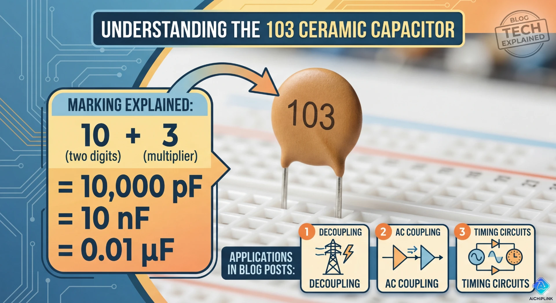
A ceramic capacitor marked "103" has a capacitance of 10,000 picofarads (pF), which equals 0.01 microfarads (µF) or 10 nanofarads (nF). The "103" marking is a three-digit code used on small ceramic capacitors where the first two digits (10) represent the base value, and the third digit (3) indicates the number of zeros to add, with the result always expressed in picofarads. This standard coding system allows manufacturers to print capacitance values on tiny components where there isn't space for full text like "0.01µF." This guide explains how to decode ceramic capacitor codes, provides conversion tables, shows common values, and demonstrates practical applications for 103 capacitors.
Quick Answer & Decoding 103
The Answer: 10,000 pF (0.01 µF)
103 Ceramic Capacitor Value:
Code: 103
Decoded: 10 + 000 (3 zeros) = 10,000 pF

Conversions:
10,000 pF = 10 nF = 0.01 µF

Common notation:
- Technical: 10 nF (nanofarad - most common)
- Older notation: 0.01 µF (microfarad)
- Base unit: 10,000 pF (picofarad)
How the 103 Code Works
Three-Digit Code Format: XYZ
Decoding Rules:
- First digit (X): First significant figure
- Second digit (Y): Second significant figure
- Third digit (Z): Number of zeros to add
- Unit: Always picofarads (pF)
Example: 103
Step 1: Take first two digits → 10
Step 2: Add number of zeros indicated by third digit → 10 + 000 (3 zeros)
Step 3: Result in picofarads → 10,000 pF
Step 4: Convert to preferred unit → 10 nF or 0.01 µF
Visual Representation
Physical Capacitor:
    [Ceramic Capacitor Body]
         ╔═══════╗
         ║  103  ║  ← Three-digit code
         ╚═══════╝
          │     │
         Lead   Lead
Code Breakdown:
   1    0    3
   ↓    ↓    ↓
First Second Number
digit digit  of zeros

Result: 10 + 000 = 10,000 pF
How to Read Ceramic Capacitor Codes
Standard Three-Digit Codes
Common Examples:
| Code | Calculation | Result (pF) | = nF | = µF | Common Use |
|---|---|---|---|---|---|
| 101 | 10 + 0 | 100 pF | 0.1 nF | 0.0001 µF | RF coupling |
| 102 | 10 + 00 | 1,000 pF | 1 nF | 0.001 µF | Bypass |
| 103 | 10 + 000 | 10,000 pF | 10 nF | 0.01 µF | Decoupling |
| 104 | 10 + 0000 | 100,000 pF | 100 nF | 0.1 µF | Bypass |
| 105 | 10 + 00000 | 1,000,000 pF | 1000 nF | 1.0 µF | Bulk |
| 223 | 22 + 000 | 22,000 pF | 22 nF | 0.022 µF | Coupling |
| 473 | 47 + 000 | 47,000 pF | 47 nF | 0.047 µF | Filtering |
Special Cases
Two-Digit Codes (Rare):
Code: 47
Meaning: 47 pF (no multiplier)
Use: Very small capacitances (typically <100 pF)
Letter Codes:
Code: 10R or 10p
Meaning: 10 pF (R or p indicates decimal point)

Code: 0.1 or 100n
Meaning: Direct notation (0.1 µF or 100 nF)
Four-Digit Codes:
Code: 4R7
Meaning: 4.7 pF (R = decimal point)
Unit Conversion Table
Essential Conversions:
1 µF (microfarad) = 1,000 nF = 1,000,000 pF
1 nF (nanofarad) = 1,000 pF = 0.001 µF
1 pF (picofarad) = 0.001 nF = 0.000001 µF

Memory Aid:
pF → nF → µF
(divide by 1,000 each step)
103 Capacitor Conversion:
10,000 pF ÷ 1,000 = 10 nF
10 nF ÷ 1,000 = 0.01 µF

Therefore:
103 = 10,000 pF = 10 nF = 0.01 µF (all equivalent)
Common Ceramic Capacitor Values
E6/E12 Series Standard Values
Common Codes You'll Encounter:
E6 Series (20% tolerance):
Code → Value (nF) → µF
101 → 0.1 nF → 0.0001 µF
102 → 1 nF → 0.001 µF
103 → 10 nF → 0.01 µF ← YOUR CAPACITOR
104 → 100 nF → 0.1 µF
105 → 1000 nF → 1.0 µF
E12 Series (10% tolerance):
Common additional values:
223 → 22 nF → 0.022 µF
333 → 33 nF → 0.033 µF
473 → 47 nF → 0.047 µF
683 → 68 nF → 0.068 µF
Tolerance Codes
Letter Markings:
| Letter | Tolerance | Meaning |
|---|---|---|
| J | ±5% | Typical ceramic |
| K | ±10% | Most common |
| M | ±20% | General purpose |
| Z | +80%, -20% | Class 2 ceramic |
Example Marking:
Capacitor marked: "103K"
103 = 10,000 pF = 10 nF
K = ±10% tolerance
Actual range: 9 nF to 11 nF
Voltage Rating
Common Voltage Codes:
Code on capacitor: "103 50V" or "103 1H"
103 = 10 nF
50V or 1H = 50V maximum working voltage

Typical ceramic capacitor voltages:
25V, 50V, 100V, 250V, 500V, 1kV
Practical Applications
Where 103 (10 nF) Capacitors Are Used
Application 1: Decoupling/Bypass Capacitors
Function: Filter high-frequency noise from power supply lines
Circuit:
+5V ──────┬──────→ IC Power Pin
          │
        [103]  ← 10 nF bypass capacitor
          │
         GND
Why 10 nF:
- Effective at filtering 1-100 MHz noise
- Low ESR (Equivalent Series Resistance)
- Small physical size
- Complements larger electrolytic capacitors (1-100 µF)
Application 2: Coupling Capacitors
Function: Pass AC signals while blocking DC
Circuit:
Audio Signal ──[103]── Amplifier Input
               10 nF   (blocks DC bias, passes audio)

Cutoff frequency calculation:
fc = 1 / (2π × R × C)
With R = 10kΩ, C = 10 nF:
fc = 1 / (2π × 10,000 × 0.00000001) = 1,591 Hz
Application 3: Timing Circuits
555 Timer Example:
Timing capacitor for 555 astable:
f = 1.44 / ((R1 + 2×R2) × C)

With C = 10 nF (103):
R1 = 10kΩ, R2 = 10kΩ
f = 1.44 / (30,000 × 0.00000001) = 4,800 Hz
Application 4: Snubber Circuits
Function: Suppress voltage spikes across inductive loads
Circuit:
Relay coil ──┬── [103 + Resistor in series]
             │   (RC snubber network)
            GND
Selecting 103 vs Other Values
When to Use 103 (10 nF):
- ✅ High-frequency decoupling (1-100 MHz)
- ✅ Digital circuit bypass (microcontrollers, logic ICs)
- ✅ Audio coupling (high-pass filter >1 kHz)
- ✅ Snubber circuits (small inductive loads)
When to Use Smaller (101, 102):
- RF circuits requiring very low capacitance
- Tuning circuits
- Oscillator frequency setting
When to Use Larger (104, 105):
- Low-frequency filtering (<1 kHz)
- Bulk power supply decoupling
- Audio coupling with lower cutoff frequency
Reading Physical Capacitors
Identification Tips
Step 1: Locate the Code
- Usually on the body of the capacitor
- May be very small (use magnifying glass if needed)
- Can be on top surface or side
Step 2: Decode the Marking
Example markings you might see:
"103"      → 10 nF (standard)
"103K"     → 10 nF ±10%
"103Z5U"   → 10 nF, Z tolerance, class 2 ceramic
"10n"      → 10 nF (direct notation)
".01"      → 0.01 µF = 10 nF (decimal notation)
Step 3: Verify Unit
- Three-digit code → Always picofarads
- Letter notation (n, u, p) → Indicates unit directly
- Decimal notation → Check context (usually µF)
Conclusion
A 103 ceramic capacitor has a capacitance of 10,000 picofarads (10 nF or 0.01 µF), decoded using the standard three-digit marking system where the first two digits (10) represent the base value and the third digit (3) indicates the number of zeros to add. This common value is widely used in digital circuit decoupling, audio coupling, and high-frequency filtering applications. Understanding ceramic capacitor codes enables quick identification of component values and proper circuit design or repair.
Key Takeaways:
✅ 103 = 10,000 pF = 10 nF = 0.01 µF (all equivalent)
✅ Decoding: First 2 digits + (third digit # of zeros) = pF
✅ Common use: Bypass/decoupling in digital circuits
✅ Tolerance: Usually ±10% (K) or ±20% (M)
✅ Substitution: Use exact value when possible
✅ Conversion: pF ÷ 1,000 = nF ÷ 1,000 = µF
✅ Reading tip: Always picofarads for three-digit codes
Need capacitors for your electronics projects? Visit AiChipLink.com for ceramic capacitor sourcing, capacitance calculations, and circuit design consultation.

Written by Jack Elliott from AIChipLink.
AIChipLink, one of the fastest-growing global independent electronic components distributors in the world, offers millions of products from thousands of manufacturers, and many of our in-stock parts is available to ship same day.
We mainly source and distribute integrated circuit (IC) products of brands such as Broadcom, Microchip, Texas Instruments, Infineon, NXP, Analog Devices, Qualcomm, Intel, etc., which are widely used in communication & network, telecom, industrial control, new energy and automotive electronics.
Empowered by AI, Linked to the Future. Get started on AIChipLink.com and submit your RFQ online today!
Frequently Asked Questions
What is the capacitance of a 103 ceramic capacitor?
A 103 ceramic capacitor has a value of 10,000 pF, which equals 10 nF or 0.01 µF. The code follows the standard three-digit system where the first two digits (10) are the base value and the third digit (3) indicates the number of zeros to add, giving 10,000 pF. In practice, engineers most commonly refer to this value as 10 nF, and it is widely used for decoupling, coupling, and high-frequency filtering applications.
How do you read a 103 capacitor code?
The 103 code is read by taking the first two digits as the base value and using the third digit as a multiplier in powers of ten. Specifically, “10” with a multiplier of 10³ results in 10,000 pF, which converts to 10 nF or 0.01 µF. Additional letters indicate tolerance (e.g., K = ±10%), so “103K” means 10 nF with ±10% tolerance.
Is a 103 capacitor the same as 0.01 µF?
Yes, a 103 capacitor is exactly equal to 0.01 µF—they represent the same capacitance in different units. Converting 10,000 pF gives 10 nF, which equals 0.01 µF, so all three notations (103, 10 nF, 0.01 µF) are interchangeable and commonly used depending on context.
What does the "3" mean in 103?
The “3” in 103 represents the multiplier, indicating how many zeros to add to the base value. In this case, it means 10 × 10³ = 10,000 pF. This third digit is effectively the power-of-ten exponent and follows a consistent pattern across capacitor codes.
Can I use a 104 instead of 103 capacitor?
Sometimes, but it depends on the circuit requirements since a 104 capacitor (100 nF) is 10× larger than a 103 (10 nF). It can be acceptable or even beneficial in power supply decoupling, but in timing circuits, filters, or tuned applications it may significantly alter performance. When accuracy matters, always use the specified value or verify the impact before substituting.


.png&w=256&q=75)


