Introduction
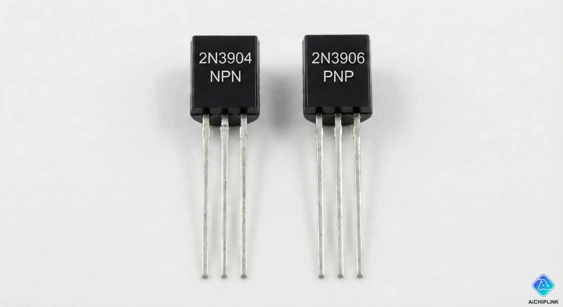
If you are diving into electronics, you will quickly encounter the two most fundamental building blocks of modern circuitry: NPN and PNP transistors. While they look identical on the outside, they function as opposites on the inside.
The Direct Answer: The primary difference between NPN and PNP transistors lies in the direction of current flow and how they are triggered.
- NPN: Current flows from the Collector to the Emitter. It requires a positive signal at the Base to turn on.
- PNP: Current flows from the Emitter to the Collector. It requires a negative (or ground) signal at the Base to turn on.
Understanding this distinction is crucial for designing functional circuits, whether you are building a simple switch or a complex amplifier. In this guide, we will clarify the practical uses, structural differences, and selection tips for each type.
NPN and PNP Transistors: Core Differences
To choose the right component, you must understand how they behave in a circuit.
Current Flow and Signal Amplification
Think of transistors as valves.
- In an NPN transistor, the "valve" opens when you apply current to the base, allowing electricity to flow out towards the ground (Emitter).
- In a PNP transistor, the "valve" opens when you pull current away from the base, allowing electricity to flow in from the power source (Emitter).
Structure and Symbol
The schematic symbol is the easiest way to identify them:
- NPN: The arrow on the Emitter leg points Not Pointing In (Outward).
- PNP: The arrow on the Emitter leg points Pointing In (Inward).
Sinking vs. Sourcing Devices
This is the most practical distinction for engineers:
- NPN is a Sinking Device: It connects the load to Ground (Negative).
- PNP is a Sourcing Device: It connects the load to VCC (Positive).
What Is a Transistor?
Before diving deeper, let’s briefly revisit the component itself.
Basic Function in Electronics
A Bipolar Junction Transistor (BJT) acts as either a switch (turning a circuit on/off) or an amplifier (taking a small signal and making it larger). It is the fundamental component that makes logic gates and microprocessors possible.
Collector, Base, and Emitter Leads
Every BJT has three pins:
- Base (B): The trigger or controller. A small current here controls a larger current across the other two pins.
- Collector (C): The main input for current (in NPN) or output (in PNP).
- Emitter (E): The outlet (in NPN) or inlet (in PNP).
NPN Transistor Explained
NPN transistors are the most common type used in electronics today.
NPN Transistor Structure
An NPN transistor consists of a layer of P-type silicon sandwiched between two layers of N-type silicon (Negative-Positive-Negative).
NPN Transistor Operation
To turn an NPN transistor ON:
- Connect the Emitter to Ground.
- Connect the Collector to the Load.
- Apply a positive voltage to the Base (relative to the Emitter). Current flows from the Collector to the Emitter.
NPN Applications and Advantages
- High Electron Mobility: Electrons move faster than "holes" (positive charge carriers), making NPN transistors generally faster and more efficient than PNP types.
- Low-Side Switching: They are ideal for switching a load by connecting it to ground (e.g., turning on an LED or motor using an Arduino).
- Cost: Due to easier manufacturing, they are often slightly cheaper and more readily available.
PNP Transistor Explained
While less common than NPN, PNP transistors are essential for specific circuit configurations.
PNP Transistor Structure
A PNP transistor features a layer of N-type silicon sandwiched between two layers of P-type silicon (Positive-Negative-Positive).
PNP Transistor Operation
To turn a PNP transistor ON:
- Connect the Emitter to the Power Source (VCC).
- Connect the Collector to the Load.
- Apply a ground or low voltage to the Base (lower than the Emitter). Current flows from the Emitter to the Collector.
PNP Applications and Advantages
- High-Side Switching: They are used when you need to control the positive side of the circuit (connecting the load to power).
- Pairing: They are often paired with NPN transistors to create "Class B" amplifiers, allowing the circuit to push and pull signals efficiently.
NPN vs PNP: Comparison and Selection
Key Differences Summary
| Feature | NPN Transistor | PNP Transistor |
|---|---|---|
| Logic | Active High (Positive triggers it) | Active Low (Ground triggers it) |
| Current Flow | Collector → Emitter | Emitter → Collector |
| Switching Type | Low-Side (Connects to Ground) | High-Side (Connects to Power) |
| Symbol Arrow | Points Out | Points In |
Choosing NPN or PNP for Your Circuit
- Choose NPN if: You are controlling a device by connecting it to Ground (Low-side switching). This is the standard for most microcontroller projects (Arduino/ESP32).
- Choose PNP if: You need to switch the power supply itself (High-side switching) or if your logic circuit provides a "Ground" signal to activate the device.
Common Mistakes and Tips
- Reversing Polarity: Putting an NPN where a PNP belongs will result in the circuit not working or the transistor overheating.
- Assuming Pinouts: Not all transistors have the same pin order (E-B-C vs C-B-E). Always check the datasheet.
- Voltage Drop: Remember that BJTs have a small voltage drop (approx 0.7V). For high-power switching, ensure you calculate for heat dissipation.
Conclusion
The choice between NPN and PNP transistors comes down to the direction of current flow and your switching logic. Remember the golden rule: NPN sinks current to ground (Active High), while PNP sources current from power (Active Low).
By selecting the right transistor for the job, you ensure your circuit is efficient, logical, and safe. Whether you are building a simple LED driver or a complex motor controller, applying this knowledge is the first step toward mastering electronics design.

Written by Jack Elliott from AIChipLink.
AIChipLink, one of the fastest-growing global independent electronic components distributors in the world, offers millions of products from thousands of manufacturers, and many of our in-stock parts is available to ship same day.
We mainly source and distribute integrated circuit (IC) products of brands such as Broadcom, Microchip, Texas Instruments, Infineon, NXP, Analog Devices, Qualcomm, Intel, etc., which are widely used in communication & network, telecom, industrial control, new energy and automotive electronics.
Empowered by AI, Linked to the Future. Get started on AIChipLink.com and submit your RFQ online today!
Frequently Asked Questions
Can I directly replace an NPN with a PNP transistor?
No. Because they require opposite trigger voltages (Positive vs. Negative) and allow current to flow in opposite directions, swapping them without redesigning the circuit will cause the circuit to fail or the component to overheat.
Why are NPN transistors more popular than PNP?
NPN transistors utilize electron flow, which is physically faster and more efficient than the "hole" flow used in PNP transistors. This generally makes NPNs faster, more efficient, and slightly cheaper to manufacture.
How can I remember the difference in their symbols?
Look at the arrow on the Emitter leg: * **NPN:** Arrow points **Out**. Mnemonic: **N**ot **P**ointing i**N**. * **PNP:** Arrow points **In**. Mnemonic: **P**ointing i**N**.
Can I use both NPN and PNP in the same circuit?
Yes, and it is very common. Circuits like **Push-Pull Amplifiers** and **H-Bridges** (used for motor direction control) utilize both types working together to control signal direction and efficiency.
Which transistor should I use with an Arduino?
For most basic switching tasks (like controlling a relay, motor, or LED), an **NPN** transistor is preferred. It works easily as a "Low-Side Switch," allowing the Arduino's positive (5V or 3.3V) signal to turn the device on efficiently.


.png&w=256&q=75)