What Is a Flip-Flop in Digital Electronics? A Clear Definition
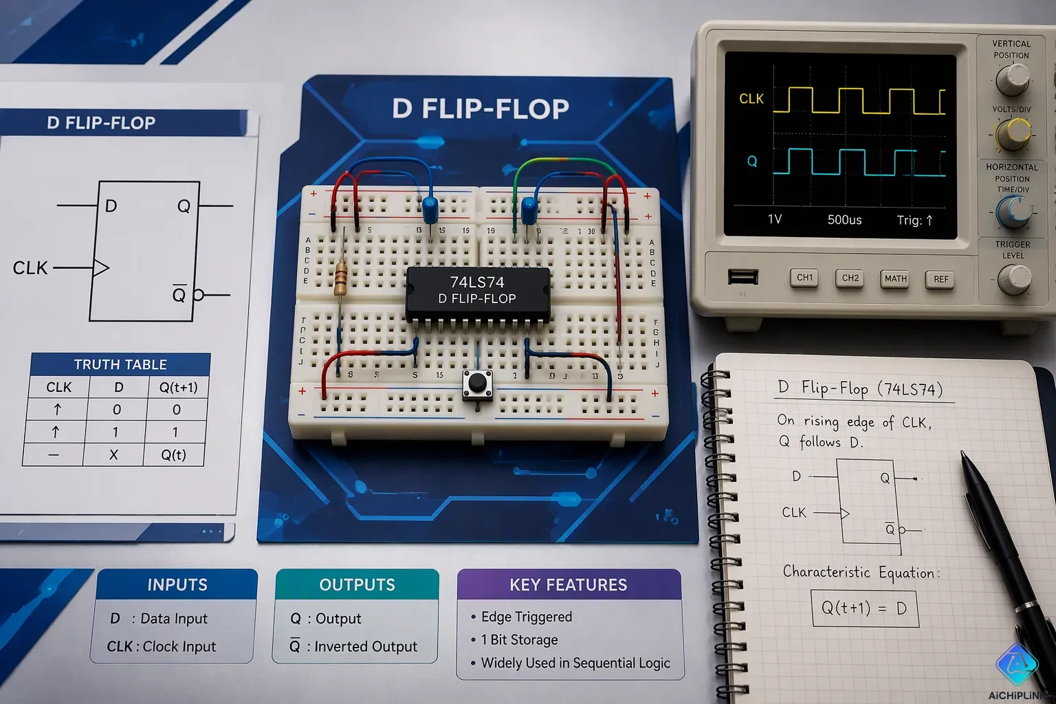
A flip-flop is a bistable sequential circuit that stores one bit of data. It keeps its state until an input tells it to change, and its output depends on those inputs. You will find this tiny memory element inside registers, counters, and state machines, where it keeps digital systems organized and predictable. The flip-flop in digital electronics works as the basic unit of stored information. This guide explains how it operates, how it differs from a latch, its main types, and where it is used. You get a clear, jargon-light explanation built for students and hobbyists. Grab a breadboard, and let us make sense of this essential circuit together.
Key Takeaways
-
A flip-flop holds one bit of data and keeps it steady until an input changes it.
-
Most flip-flops change only when the clock signal hits an edge, which makes digital systems easy to predict.
-
The four main types are SR, JK, D, and T, and each one has its own special job.
-
Flip-flops are different from latches: latches listen while they are enabled, but flip-flops listen only at clock edges.
-
Flip-flops are used to build registers, counters, and synchronizers in computers and electronics.
Flip-Flop in Digital Electronics: Core Definition
A flip-flop is a sequential digital electronic circuit with two stable states. It holds one bit of binary data, either a 0 or a 1. That one stored value is the base of every register and memory block you will meet. Engineers often call this part the basic digital memory circuit because it remembers a value after the input goes away.
Two Stable States
The circuit gets the name bistable multivibrator from its two resting conditions. In state 0, the internal nodes settle into one pattern. In state 1, they settle into the opposite pattern. Both patterns are stable, so the circuit can store binary states for as long as power stays on. You can think of it as a light switch with a memory: it stays where you left it.
A key behavior comes from this design. The circuit holds its state until an input tells it to change. Feed it the right signal, and the internal feedback loop flips to the other stable condition. Remove that signal, and the new state stays. This is how a flip-flop can store one bit across millions of clock cycles without drifting.
Clock Edge and Memory Role
Most flip-flops update their output only on a clock edge, either the rising edge or the falling edge. This edge-triggered behavior sets them apart from simple combinational logic. A combinational gate reacts to its inputs at all times. A flip-flop samples its input at one exact moment and ignores it otherwise. That rule is what makes sequential logic predictable.
Timing rules govern that sampling moment. Two parameters matter most:
-
Setup time: the minimum time before the clock's active edge that the data input must stay stable.
-
Hold time: the minimum time after the clock's active edge that the data input must remain stable.
Break either window, and the flip-flop may capture the wrong value or enter a metastable state. Designers check these windows with simple relations. For zero skew, the setup check is Tck->q + Tprop + Tsetup < Tperiod, and the hold check is Tck->q + Tprop > Thold. Add clock skew, and the setup check becomes Tck->q + Tprop + Tsetup - Tskew < Tperiod, while the hold check becomes Tck->q + Tprop > Thold + Tskew.
Speed varies by logic family. The table below shows typical propagation delay, the time from the clock edge to a valid output:
| Logic Family | Typical Propagation Delay |
|---|---|
| TTL flip-flops | 2–10 ns |
| ECL flip-flops | sub-nanosecond (below 1 ns) |
Faster families shrink the delay, yet the setup and hold rules still apply. Every flip-flop in digital electronics obeys them, and every chain of sequential logic depends on them. Master these two ideas, the stable pair of states and the clock edge, and the rest of digital memory becomes much easier to read.
Flip-Flop vs. Latch
Both parts are bistable storage circuits. Each one holds a bit until a control signal tells it to change. The difference between latches and flip-flops comes down to one question: when does the output listen? A latch listens while its enable signal stays high. A flip-flop listens only at a clock edge. That one rule shapes how you choose between them.
Level-Triggered vs. Edge-Triggered
A level-triggered latch is transparent while its enable input is high. The outputs follow the data inputs during that time. Drop the enable low, and the outputs hold the last value. Common parts show this pattern clearly: the 74LS75 is a 4-bit latch, the 74HC373 and 74LS373 are octal latches with tri-state outputs, and the 74HC573 is an octal latch with a different pin-out.
An edge-triggered flip-flop works in a different way. It captures its input at the exact moment the clock changes, either rising or falling. Input changes at all other times are ignored. This edge-triggered storage element gives you exact control over when data is stored. The table below sums up the flip-flop vs latch contrast:
| Feature | Latch | Flip-Flop |
|---|---|---|
| Trigger type | Level-triggered | Edge-triggered |
| Control signal | Enable signal | Clock signal |
| Output change | Changes while enabled | Changes only at clock edge |
| Timing control | Less precise | More accurate |
| Stability | Lower | Higher |
| Complexity | Simple | More complex |
| Common use | Simple circuits | Synchronous systems |
Choosing the Right One
Latches fit simple, fast, transparent storage. A microprocessor bus saves pins by sharing address and data lines. An octal latch such as the 74HC373 holds the address while the bus carries data, and its tri-state outputs free the bus when idle. Latches also serve in register files, pipeline stages, debouncing, and signal gating for power management.
Synchronous designs usually need an edge-triggered flip-flop. These parts update only on the clock edge, which removes glitches that latches can pass along. They also prevent race conditions and hold-time violations that latches may cause in RTL designs. That is why microprocessors, data registers, and memory circuits rely on them as the standard storage element. Use a latch for quick transparent holding, and reach for a flip-flop when timing must stay predictable.
Main Flip-Flops in Digital Electronics
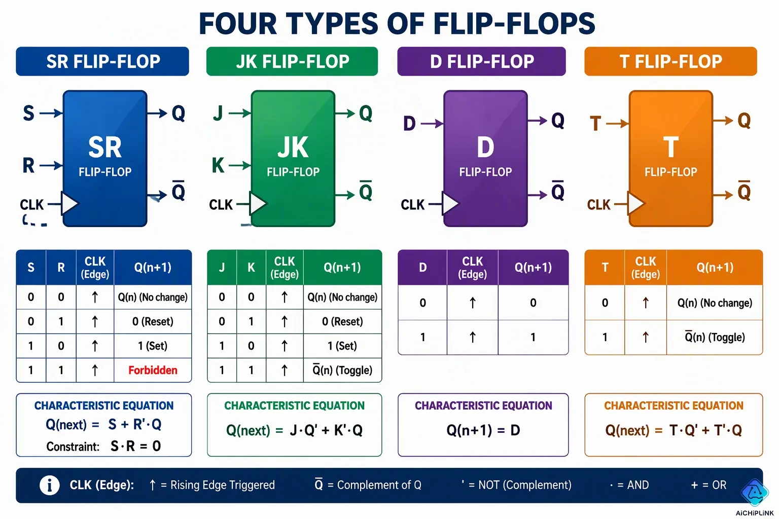
Four main types of flip-flops serve most designs: SR, JK, D, and T. Each type of flip-flop in digital electronics has its own truth table and characteristic equation. A truth table lists the next output for every input combination. The characteristic equation states that same rule as a short Boolean expression. You will see both forms in datasheets and textbooks.
SR and JK Types
The s-r flip-flop is the simplest type. It sets the output with S and resets it with R. Its sr flip-flop truth table forbids the case where S and R are both 1. That input combination drives both outputs high and breaks the stored state. The forbidden state matters in practice. A designer must avoid S = 1 and R = 1 at the same time. The s-r flip-flop characteristic equation reads Q(next) = S + R'·Q, with the constraint S·R = 0.
SR: Q(next) = S + R̄·Q, with the constraint S·R = 0
JK: Q(next) = J·Q̄ + K̄·Q
The j-k flip-flop fixes that flaw. It allows both inputs high, and that case toggles the output. Its jk flip-flop truth table therefore has no forbidden row. The j-k flip-flop behaves like an s-r flip-flop for the other three input pairs. Its characteristic equation is Q(next) = J·Q' + K'·Q. Both equations appear in the table below.
| Flip-Flop | Characteristic Equation |
|---|---|
| SR | Q(N+1) = Q(N)·R' + S·R' |
| JK | Q(N+1) = J·Q'(N) + K'·Q(N) |
D Flip-Flop and T Type
The d (data) flip-flop is the most widely used flip-flop in digital electronics. A d flip flop copies its input to the output at the clock edge. Its d flip-flop truth table is simple: the next output always equals D. The characteristic equation is Q(n+1) = D.
| Clock Edge | D (Input) | Q(n+1) (Next Output) |
|---|---|---|
| ↑ (trigger) | 0 | 0 |
| ↑ (trigger) | 1 | 1 |
| No clock edge | X | Q(n) (no change) |
A positive-edge-triggered d flip-flop samples D only at the rising edge. A d flip-flop ignores D at all other times. A pulse on D that falls entirely between edges is not captured. This edge-triggered flip-flop behavior makes d flip-flops the standard storage cell in registers and memory. Each d flip flop holds exactly one bit. This simple rule makes d flip-flops easy to chain into pipelines.
The t flip-flop toggles instead of copying. When T is 1, the output flips. When T is 0, it holds. Its characteristic equation is Q(t+1) = T ⊕ Q(t).
| T | Q(t) | Q(t+1) | Operation |
|---|---|---|---|
| 0 | 0 | 0 | Hold |
| 0 | 1 | 1 | Hold |
| 1 | 0 | 1 | Toggle |
| 1 | 1 | 0 | Toggle |
You can build a t flip-flop from a d flip flop by tying D to the inverted output. A t flip-flop divides the clock by two. Counters use this toggle action. The toggle action suits binary counting, where each stage flips at half the rate of the one before it. A d flip flop also appears in shift registers, where d flip-flops pass bits along. Chain several d flip flops, and you get a multi-bit register. Registers built from d flip-flops store multi-bit words. Together, these types of flip-flops in digital electronics cover nearly every sequential logic task. Each type has a clear job, and the truth table tells you which one fits. Study the truth tables of flip flops above, and you can predict any output.
Inside a Flip-Flop
Gate-Level Construction
You can build a basic flip-flop from just a handful of gates. The cross-coupled arrangement does the real work. Each gate output feeds back into the other gate's input, and that loop is what creates memory. Boolean logic alone produces this effect. No special component stores the bit; the feedback path holds it.
A basic flip-flop can be constructed using four-NAND or four-NOR gates.
Trace the loop and you see why it holds. Set one output high, and the feedback forces the opposite output low. That pair of values stays put because each gate keeps confirming the other. This is the heart of storing binary states. The flip-flop circuit you build on a breadboard follows the same principle, even when the gates sit inside one chip.
State Transitions
A state change waits for the clock edge. At that instant, the inputs present determine the next state. For a D flip-flop, D=1 sets Q=1 and D=0 sets Q=0. For a T flip-flop, T=1 toggles Q while T=0 holds it. The output updates right after the transition, and the feedback paths loop the output back to hold the state stable until the next qualifying edge.
| Flip-Flop Type | Input at Clock Edge | Resulting Output |
|---|---|---|
| D | D = 1 | Q = 1 |
| D | D = 0 | Q = 0 |
| T | T = 1 | Q toggles |
| T | T = 0 | Q unchanged |
Picture the timing in plain steps. The clock sits low, and the flip-flop ignores its data input. The edge arrives, and the input value is captured at that exact moment. The output then settles to the new level and stays there. This edge-only reaction gives you synchronization and timing accuracy across sequential circuits.
Applications of Digital Electronics - Flip-Flops
Registers and Counters
A register is a group of flip-flops that stores multi-bit data. Tie eight d flip-flops to one shared clock, and you hold a full byte. Each d flip flop keeps exactly one bit, so the register width grows with every stage you add. You will find these blocks inside processors, where they hold operands and addresses between operations. A shift register takes the idea further. It passes each bit to the next stage on every clock edge, which turns serial data into parallel data.
Counters chain flip-flops so each stage clocks the next. A t flip-flop toggles at every active edge, so its output runs at half the input rate. String several stages together, and the count climbs in binary. This chaining is one of the most common uses of flip-flops in digital electronics. A ripple counter needs no extra gates, which keeps it small and cheap.
Synchronizers and Dividers
A frequency divider builds on that same toggle action. Each d flip-flop wired as a divide-by-2 stage halves the clock. The least-significant output bit toggles at half the input rate, the next bit at one-quarter, the third at one-eighth. Three divide-by-2 stages give you a divide-by-8 output. Add a few logic gates to the chain, and you can reach odd ratios such as divide-by-5. The output stays frequency- and phase-coherent with the source clock, even when temperature shifts. That coherence matters in digital electronics - flip-flops that divide a clock keep every downstream block in step.
A synchronizer solves a different problem. Asynchronous signals arrive at random times, so a positive-edge-triggered d flip-flop samples them at a known clock edge. Chain two d flip-flops back to back, and the first stage absorbs the timing uncertainty before the second passes a clean value into your sequential logic. Delay circuits built from d flip-flops use the same idea. A d flip flop copies its input at the clock edge. Each d flip flop in the path pushes the signal one clock period later, which lets you align data with control signals. A single flip-flop in digital electronics therefore does far more than store a bit.
A flip-flop is a bistable sequential circuit that stores one bit of data. It holds that bit until an input tells it to change. You now know the key differences: two stable states, clock-edge updates, and the four main types — SR, JK, D, and T. Each type has a clear job, from the D flip-flop's role in registers to the T type's toggle action in counters. These circuits keep different parts of a system in step so they work as one. They also give sequential logic the memory element it needs to keep its state. Grab a breadboard and build a simple flip-flop circuit yourself — watching that first bit hold steady makes everything click.

Written by Jack Elliott from AIChipLink.
AIChipLink, one of the fastest-growing global independent electronic components distributors in the world, offers millions of products from thousands of manufacturers, and many of our in-stock parts is available to ship same day.
We mainly source and distribute integrated circuit (IC) products of brands such as Broadcom, Microchip, Texas Instruments, Infineon, NXP, Analog Devices, Qualcomm, Intel, etc., which are widely used in communication & network, telecom, industrial control, new energy and automotive electronics.
Empowered by AI, Linked to the Future. Get started on AIChipLink and submit your RFQ online today!
Frequently Asked Questions
What makes a flip-flop different from a logic gate?
A logic gate reacts to its inputs at all times. A flip-flop remembers. It holds one bit and changes only when an input directs it. That memory comes from feedback, where each gate output feeds the other gate's input. This stored state is why sequential logic can track time and sequence.
Why does the clock edge matter so much?
The clock edge sets the exact moment your flip-flop samples its input. Data changes at other times get ignored. This rule keeps every stage in step. Setup time and hold time define the safe window around that edge. Respect both windows, and your circuit stays predictable.
Which type should a beginner start with?
Start with the d flip flop. Its rule is simple: the output copies the input at the clock edge. You can build a t flip-flop from it by tying the input to the inverted output. The s-r flip-flop comes next, and the j-k type follows once you understand the forbidden state.
What happens if timing rules break?
The flip-flop may capture the wrong value. In the worst case, it enters a metastable state and hovers between 0 and 1 for a short time. A synchronizer with two chained stages helps tame asynchronous inputs. Good timing practice keeps your sequential logic reliable.
Does a flip-flop keep its data without power?
No. Both stable states depend on power. Cut the supply, and the stored bit disappears. That is why systems add backup memory or nonvolatile storage for data that must survive a shutdown. A flip-flop is fast working memory, not permanent storage.