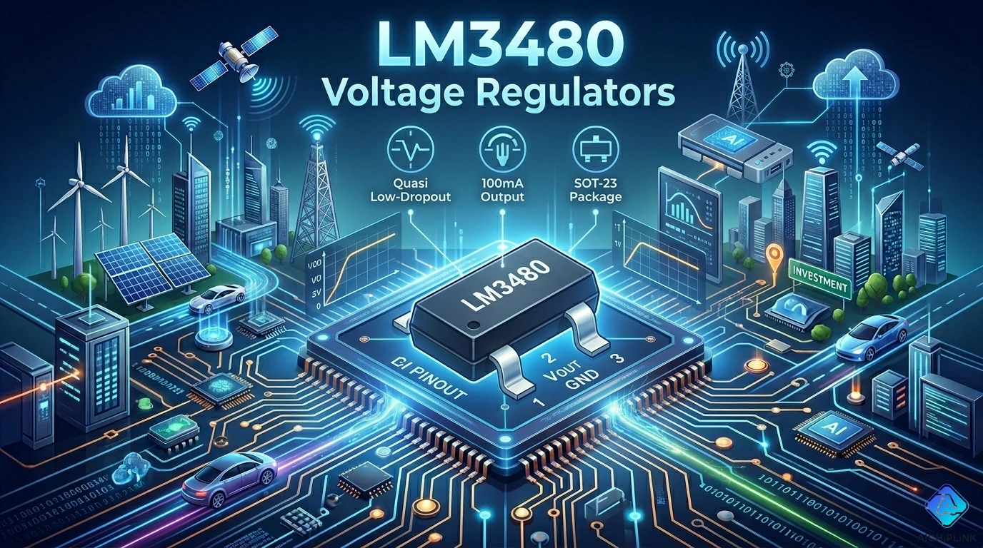
The LM3480 datasheet says 100 mA guaranteed minimum output current. Three pins, SOT-23 package, one decoupling cap each side — looks like the simplest design win possible. Then an engineer specifies the LM3480-12 to generate a 12V bias rail from a 24V supply, loads it with 80 mA, and watches the output collapse when the board temperature rises above 40°C. The chip throttles itself back. The math was never done.
Here is the math: with a 24V input and 12V output at 80 mA, the LM3480 must dissipate (24V − 12V) × 80 mA = 960 mW of heat — in a package with a junction-to-ambient thermal resistance of roughly 269°C/W. At 25°C ambient: Tj = 25 + (0.96W × 269°C/W) = 25 + 258 = 283°C. Maximum junction temperature is 150°C. The thermal protection activates and folds back the output long before 80 mA is reached.
The LM3480 is an excellent regulator, genuinely useful for dozens of applications. But using it correctly requires understanding which versions work within the SOT-23 power budget and which versions demand careful current derating. This guide covers everything needed to make that determination before a single component is ordered.
1.0 Part Number Decoded: Every Field in LM3480IM3-X.X/NOPB
Texas Instruments encodes the full ordering information for the LM3480 in the part number suffix. Here is the complete breakdown:
LM3480 — Base product name. LM = Linear Monolithic (TI/National Semiconductor product family prefix), 3480 = device identifier within the linear regulator family.
IM3 — Package and temperature grade:
- I = Industrial temperature range (−40°C to +125°C junction temperature for operation)
- M3 = SOT-23 3-lead package (M = surface mount, 3 = 3 pins)
-3.3 / -5.0 / -12 / -15 — Fixed output voltage version:
- -3.3 = 3.3V output
- -5.0 = 5.0V output
- -12 = 12V output
- -15 = 15V output
(optional X) — Tape-and-reel packaging indicator. LM3480IM3X-5.0 is tape-and-reel; LM3480IM3-5.0 is tube/tray.
/NOPB — RoHS compliant, lead-free finish (No Lead, No PB). All current production LM3480 variants carry this suffix.
Complete current ordering matrix:
| Output Voltage | Tube/Tray | Tape & Reel |
|---|---|---|
| 3.3V | LM3480IM3-3.3/NOPB | LM3480IM3X-3.3/NOPB |
| 5.0V | LM3480IM3-5.0/NOPB | LM3480IM3X-5.0/NOPB |
| 12V | LM3480IM3-12/NOPB | LM3480IM3X-12/NOPB |
| 15V | LM3480IM3-15/NOPB | LM3480IM3X-15/NOPB |
Note on package marking: Due to the small size of the SOT-23 package, the full part number is not silkscreened on the device. A brief alphanumeric code is used instead. Verify received components by running the marking code through TI's online part marking decoder or the package marking table in the datasheet before use in production.
2.0 Specifications at a Glance
All parameters from the TI LM3480 datasheet (Rev. H, September 2015):
- Output voltages: 3.3V, 5.0V, 12V, 15V (fixed, not adjustable)
- Guaranteed minimum output current: 100 mA (at 25°C, subject to thermal limitation — see Section 4)
- Maximum input voltage: 30V (absolute maximum for IN-to-GND)
- Maximum dropout voltage: 1.2V at 100 mA, full temperature range
- Output voltage accuracy: ±5% over full load and temperature range
- Quiescent current: Approximately 1–3 mA (ground pin current)
- Junction temperature range (operation): −40°C to +125°C
- Thermal resistance (θJA): 269.6°C/W (SOT-23, no heatsink, Rev. H)
- Maximum power dissipation at TA = 50°C: 370 mW (Rev. H: (150°C − 50°C) / 269.6°C/W)
- Thermal shutdown: Active — self-limits junction temperature to approximately 150°C
- Short-circuit protection: Built-in current limiting
- Input capacitor: 0.1 µF minimum required for stability
- Output capacitor: 0.1 µF minimum required for stability
- ESR limitation on output capacitor: None specified — high ESR degrades transient response but does not cause instability
- Package: SOT-23 (3-lead), surface mount
- RoHS / Lead-free: Yes (/NOPB suffix)
3.0 How the LM3480 Works: Quasi-Low-Dropout Architecture
The LM3480 is described as a "quasi-low-dropout" regulator. Understanding what "quasi" means here explains both the capability and the limitation of the device.
Traditional LDO regulators use a PMOS pass transistor between input and output. The dropout voltage of a PMOS LDO is approximately Rds_on × ILOAD — very low, often under 200 mV at full load. These are true LDOs.
Standard positive regulators (like LM78Lxx) use an NPN bipolar pass transistor in an emitter-follower configuration. The dropout voltage is VCE_sat + base-emitter voltage overhead — typically 2 to 2.5V. High dropout.
The LM3480's "quasi-LDO" approach uses an NPN pass transistor but in a common-emitter (rather than emitter-follower) configuration, driven by a PNP driver transistor. This configuration allows the output to approach within about 1.2V of the input — significantly better than the LM78Lxx's 2.0–2.5V dropout, but not as low as a PMOS LDO's 150–200 mV dropout.
The 1.2V maximum dropout means:
- The LM3480-3.3 can regulate from a 4.5V input — enabling a 3.3V rail from a 5V ±5% supply (minimum 4.75V, which provides 1.45V of headroom above the 1.2V dropout) — the intended application TI specifically calls out
- The LM3480-5.0 requires at least 6.2V input minimum for guaranteed regulation
- The LM3480-12 requires at least 13.2V input minimum
- The LM3480-15 requires at least 16.2V input minimum
4.0 ⚠️ Four Pitfalls That Cause LM3480 Designs to Fail
Pitfall 1: Specifying the 12V or 15V version without calculating actual deliverable current
This is the most critical and most common failure mode. The 100 mA rating is real — but only when the power dissipated in the package stays within the thermal limit. In a SOT-23 package with θJA = 269.6°C/W, the maximum power dissipation at 25°C ambient is:
P_max = (TJ_max − TA) / θJA = (150°C − 25°C) / 269.6°C/W = 464 mW
Power dissipated = (VIN − VOUT) × ILOAD
For LM3480-12 with VIN = 15V:
- P = (15 − 12) × 0.1A = 300 mW → Below limit, 100 mA works at 25°C
- At 70°C ambient: P_max = (150 − 70) / 269.6 = 297 mW → Barely above limit; derate
For LM3480-12 with VIN = 24V:
- P = (24 − 12) × ILOAD
- Maximum ILOAD = 464 mW / 12V = 38.7 mA at 25°C ambient
- At 50°C ambient: P_max = (150 − 50) / 269.6 = 371 mW → max ILOAD = 30.9 mA
- At 70°C ambient: max ILOAD = 24.7 mA
An engineer expecting 100 mA from LM3480-12 at 24V input in a 70°C enclosure will get roughly 25 mA before thermal protection activates. The general formula for maximum current:
ILOAD_max = (TJ_max − TA) / (θJA × (VIN − VOUT))
Calculate this before specifying the part for any 12V or 15V application.
Pitfall 2: Omitting or undersizing the input and output capacitors
The LM3480 datasheet specifies a minimum of 0.1 µF on both input and output for stability. These capacitors are not optional — they are part of the stability network. A design that omits them (or uses incorrect values during prototype bring-up because "it was the only cap available") may appear to work at light load and room temperature but will oscillate or produce excessive noise on the output under load transients or at elevated temperature. The 0.1 µF minimum is a ceramic capacitor value; X5R or X7R dielectric is appropriate. There is no maximum capacitance limit specified — larger values improve transient response. ESR is not constrained to a specific range for stability, though very high ESR (> 10 Ω) will degrade transient response.
Pitfall 3: Connecting the input above 30V in an attempt to widen the input range
The LM3480 supports inputs up to 30V — this is the absolute maximum, not the operating target. Some designers targeting 24V nominal industrial supplies assume the 30V rating provides comfortable margin. However, 24V nominal on an industrial rail can swing up to 28–30V under light load conditions in some supply designs, and inductive switching spikes can push the input pin momentarily above 30V during transient events (motor start-up, solenoid switching, load dump). For applications where the input can approach or exceed 24V nominal, add a series protection resistor (100 Ω to 1 kΩ) at the input or use an input clamp diode (5.1V to 28V TVS placed input-to-ground after the resistor) to protect against transient overvoltage.
Pitfall 4: Assuming the LM3480 is interchangeable with the LM78Lxx in all designs
TI markets the LM3480 as a "tiny alternative to industry standard LM78Lxx series." The pinout of the LM3480 SOT-23 package is IN, GND, OUT (pin 1, 2, 3 respectively). The LM78L series in TO-92 package is OUTPUT, GND, INPUT (pin 1, 2, 3 in the standard TO-92 orientation). These are not pin-compatible — a direct footprint substitution will result in a nonfunctional circuit. Additionally, the LM78Lxx operates to a maximum of 150 mA versus the LM3480's 100 mA, and has higher dropout (2–2.5V vs 1.2V). Check the pinout and current requirement before specifying the LM3480 as a form-factor replacement for an existing LM78L design.
5.0 Application Circuit and Design Notes
Minimum application circuit:
The LM3480 requires only three external components for a complete power supply:
- C_IN = 0.1 µF ceramic (X5R/X7R, ≥ input voltage rating) from IN pin to GND
- C_OUT = 0.1 µF ceramic (X5R/X7R, ≥ output voltage rating) from OUT pin to GND
- The LM3480 itself (3 pins)
For improved transient performance — particularly in applications with rapidly changing load currents — add a larger output capacitor (1–10 µF) in parallel with the 0.1 µF. For high-noise input environments, add a larger input capacitor (1–10 µF) in parallel.
PCB layout notes:
Place C_IN and C_OUT within 2 mm of the LM3480's IN and OUT pins respectively. The ground connections of both capacitors should be as short as possible, ideally connected to a solid ground pour directly beneath the LM3480. In a 2-layer PCB, a local ground pour on the bottom copper layer beneath the SOT-23 footprint reduces effective ground impedance and slightly improves heat dissipation.
Thermal layout for maximum power dissipation:
For applications where the power dissipation approaches the package limit, extending the copper pours connected to the SOT-23 leads reduces the effective θJA. TI's datasheet specifies 269.6°C/W for the worst-case condition of no copper spreading. With a 1 cm² copper fill connected to the GND pin (which carries the pass transistor's collector in this topology), θJA can be reduced to approximately 250°C/W — a modest but useful improvement. Significant further reduction requires a larger footprint package; SOT-23 is inherently limited to the 300–370 mW range regardless of copper spreading.
The 3.3V version application (LM3480IM3-3.3) — most useful configuration:
The LM3480-3.3 directly addresses a common circuit board requirement: generating a 3.3V logic/analog rail from the system 5V supply. The power dissipation is (5V − 3.3V) × ILOAD = 1.7V × ILOAD. At 100 mA: P = 170 mW — well within the 370 mW package limit at 50°C ambient. This is the configuration where the LM3480 genuinely delivers its rated 100 mA with comfortable margin. At ILOAD = 100 mA and TA = 85°C: TJ = 85 + (0.170 × 269.6) = 85 + 46 = 131°C — within the 150°C maximum.
6.0 Comparison: LM3480 vs LM78Lxx, LM2950, and MCP1700
| Parameter | LM3480 | LM78L05/12/15 | LM2950 | MCP1700 |
|---|---|---|---|---|
| Max input voltage | 30V | 30–35V | 30V | 6V |
| Output voltages | 3.3, 5, 12, 15V | 5, 6, 8, 9, 10, 12, 15, 24V | 3–29V (adj) | 1.2–5V (adj) |
| Max output current | 100 mA | 100–150 mA | 100 mA | 250 mA |
| Dropout voltage | 1.2V (max) | 2.0–2.5V | 0.4–0.7V (LDO) | 0.178V (true LDO) |
| Package | SOT-23 (3-pin) | TO-92, SOT-89 | SOT-23 (5-pin) | SOT-23 (3-pin) |
| Quiescent current | ~1–3 mA | ~3–5 mA | ~75 µA | 1.6 µA |
| Output accuracy | ±5% | ±5–10% | ±0.5–1% | ±0.4% |
| Adjustable output | No (fixed) | No (fixed) | Yes | Yes |
| Max input for 3.3V out | 30V | N/A | 30V | 6V only |
| Best for | High-Vin bias rails | Industrial legacy, TO-92 | Precision, adjustable | Ultra-low IQ battery |
When LM3480 wins over LM78Lxx: The 1.2V vs 2.5V dropout difference is the decisive factor when the input voltage is close to the output. The canonical case is 3.3V from 5V ±5%: minimum input is 4.75V, requiring less than 1.45V dropout — the LM78L cannot guarantee regulation here, the LM3480 can. Also, the SOT-23 footprint saves PCB area in dense designs where TO-92 is impractical.
When LM78Lxx wins over LM3480: When more output voltage options are needed (6V, 8V, 9V, 10V, 24V are not available in the LM3480 family), when the slightly higher current capability of LM78L150 mA matters, or when TO-92 through-hole mounting is required.
When MCP1700 wins: Ultra-low-power battery-operated systems where the 1.6 µA quiescent current of the MCP1700 versus 1–3 mA of the LM3480 extends battery life substantially. Note: MCP1700 maximum input is only 6V — incompatible with any design requiring more than ~5.8V input voltage.
When LM2950 wins: Precision reference voltage applications requiring ±0.5% output accuracy rather than the LM3480's ±5%, or adjustable output voltage.
7.0 Sourcing the LM3480
The LM3480 is manufactured by Texas Instruments (who acquired National Semiconductor in 2011, the original LM3480 designer). It is an active, standard-production part available from authorized distributors including DigiKey, Mouser, and Arrow, in all four voltage variants and both tape-and-reel and tube packaging.
Typical pricing: $0.30–$0.60 per unit at 1,000-piece quantities (varies by voltage variant and packaging format).
Counterfeit awareness: The LM3480 is widely copied in the secondary market, particularly the 5V and 12V versions. Counterfeits often exhibit worse output accuracy (outside ±5%), higher dropout voltage, and may lack the thermal shutdown protection — meaning they can be destroyed by thermal stress rather than gracefully limiting current. Verify received parts from the abbreviated package marking against TI's official marking table, and confirm the output voltage with a calibrated meter at light load before powering production boards.
For verified authentic Texas Instruments LM3480 inventory with competitive pricing, visit aichiplink.com.
8.0 Real Questions from Engineers Using the LM3480
Q: I need to power a 12V circuit from a 24V industrial rail using the LM3480-12. The load draws 50 mA continuously. The enclosure ambient reaches 60°C in summer. Will it work?
A: Work through the calculation. Power dissipation = (24V − 12V) × 0.050A = 600 mW. Maximum allowable dissipation at 60°C ambient: P_max = (150°C − 60°C) / 269.6°C/W = 90°C / 269.6°C/W = 334 mW. Your required dissipation (600 mW) exceeds the package limit by 79%. The thermal protection will activate and the output will collapse. The LM3480-12 cannot safely deliver 50 mA from a 24V input at 60°C ambient. You have three options: (1) Use a different regulator with a larger package (TO-252 or TO-263 footprint), (2) Pre-regulate the 24V to 15V with a switching converter, then use LM3480-12 on the 15V rail (dissipation = (15−12) × 50 mA = 150 mW, well within limit), or (3) Use a higher-power regulator such as the LM317 in a suitable heatsinkable package.
Q: What is the minimum output capacitor I can use on the LM3480? Can I use a 1 µF ceramic instead of 0.1 µF?
A: Yes — 1 µF is perfectly fine. The 0.1 µF is the minimum for stability; larger values improve transient performance and there is no maximum limit. A 1 µF X5R 0402 ceramic capacitor is a common choice that provides both the stability margin and better load transient response without significantly increasing PCB area. Avoid tantalum capacitors unless the ESR is confirmed to be in a reasonable range; very low-ESR tantalums (< 0.1 Ω) at large capacitances can theoretically cause issues with some linear regulators, though the LM3480 datasheet does not specify an ESR constraint.
Q: The LM3480 datasheet says it is a "quasi-LDO" but I need a true LDO for a 3.7V LiPo to 3.3V supply. Is the LM3480-3.3 suitable?
A: It is marginal. The LM3480 guarantees a maximum dropout of 1.2V at 100 mA. A 3.7V nominal LiPo discharges to 3.0V at end-of-life. Minimum headroom = 3.0V − 3.3V = −0.3V — the battery is already below the output voltage at end-of-life, which no linear regulator can overcome. Even at nominal 3.7V, the headroom is only 3.7 − 3.3 = 0.4V — well below the 1.2V maximum dropout guarantee, meaning regulation is not guaranteed at 100 mA. For a LiPo to 3.3V supply, use a true LDO with dropout under 300 mV (MCP1700, MIC5205, AP2112K, or TLV1117-3.3) that maintains regulation at the 3.0V discharge endpoint. The LM3480-3.3 is excellent for 5V to 3.3V regulation, but not for LiPo applications.
Q: I see LM3480 listed as "active" on TI's website but also a newer part LM3480A recommended. What changed?
A: TI has released the LM3480A as an updated version with improved specifications — notably a lower dropout voltage and improved output accuracy — while maintaining the same SOT-23 footprint and pin assignment. For new designs, TI recommends the LM3480A. Existing designs using the LM3480 can continue with the original part without redesign, as it remains in active production. The LM3480A is not guaranteed to be a 100% drop-in for all specifications — verify the LM3480A datasheet's parameters match your design requirements before substituting in an existing qualified design.
9.0 Quick Reference Card
Part Number Quick Decode:
| Field | Meaning |
|---|---|
| LM3480 | TI/National quasi-LDO linear regulator |
| IM3 | Industrial grade, SOT-23 3-lead package |
| -3.3 / -5.0 / -12 / -15 | Output voltage (V) |
| X (optional) | Tape-and-reel packaging |
| /NOPB | RoHS lead-free |
The Critical Formula — Always Calculate Before Specifying:
ILOAD_max = (150°C − TA) / (269.6°C/W × (VIN − VOUT))
| VIN → VOUT | Max current at 25°C | Max current at 50°C | Max current at 70°C |
|---|---|---|---|
| 5V → 3.3V (1.7V diff) | 273 mA* | 219 mA* | 175 mA* |
| 9V → 5V (4V diff) | 116 mA | 93 mA | 74 mA |
| 12V → 5V (7V diff) | 66 mA | 53 mA | 43 mA |
| 15V → 12V (3V diff) | 155 mA* | 124 mA* | 99 mA |
| 24V → 12V (12V diff) | 38 mA | 31 mA | 25 mA |
| 24V → 15V (9V diff) | 52 mA | 41 mA | 33 mA |
*Values marked with asterisk exceed the 100 mA rated current — the device current limit (100 mA guaranteed) becomes the binding constraint, not thermal.
Version Selection Summary:
| Version | Best Application | Watch Out For |
|---|---|---|
| LM3480-3.3 | 5V → 3.3V bias supply | Not for LiPo batteries |
| LM3480-5.0 | 9–12V → 5V logic supply | Verify thermal at high Vin |
| LM3480-12 | 13.5–18V → 12V analog bias | Heavily derate at 24V input |
| LM3480-15 | 18–24V → 15V op-amp supply | Barely usable at 24V input |
Minimum Required Capacitors:
- C_IN: 0.1 µF ceramic (X5R/X7R), voltage-rated to VIN
- C_OUT: 0.1 µF ceramic (X5R/X7R), voltage-rated to VOUT
- Recommended: 1 µF on output for improved transient response
For sourcing Texas Instruments LM3480 in all voltage variants and packaging options at verified authentic pricing, visit aichiplink.com.

Written by Jack Elliott from AIChipLink.
AIChipLink, one of the fastest-growing global independent electronic components distributors in the world, offers millions of products from thousands of manufacturers, and many of our in-stock parts is available to ship same day.
We mainly source and distribute integrated circuit (IC) products of brands such as Broadcom, Microchip, Texas Instruments, Infineon, NXP, Analog Devices, Qualcomm, Intel, etc., which are widely used in communication & network, telecom, industrial control, new energy and automotive electronics.
Empowered by AI, Linked to the Future. Get started on AIChipLink and submit your RFQ online today!
Frequently Asked Questions
Can LM3480 really deliver 100 mA?
Yes, but only under low thermal stress—while the LM3480 voltage regulator is rated for 100 mA, high input-output voltage differences (e.g., 24V→12V) drastically reduce usable current due to SOT-23 heat limits, often to 20–40 mA in real conditions.
What’s the minimum capacitor requirement?
The LM3480 voltage regulator requires at least 0.1 µF on both input and output for stability, but using 1 µF or higher improves transient response without risking instability.
Is LM3480 suitable for LiPo to 3.3V conversion?
No—the LM3480 voltage regulator has ~1.2V dropout, making it unsuitable for low-headroom sources like LiPo batteries; a true LDO with <300 mV dropout is recommended instead.
Can LM3480 replace LM78Lxx directly?
Not directly—the LM3480 voltage regulator has different pinout, lower dropout, and lower current capability, so footprint and electrical differences must be verified before substitution.
What’s the difference between LM3480 and LM3480A?
The newer LM3480A voltage regulator offers improved dropout and accuracy while keeping the same footprint, making it the better choice for new designs, though not always a drop-in spec replacement.