How to Derive the Current Divider Formula from Ohm's Law and Kirchhoff's Laws
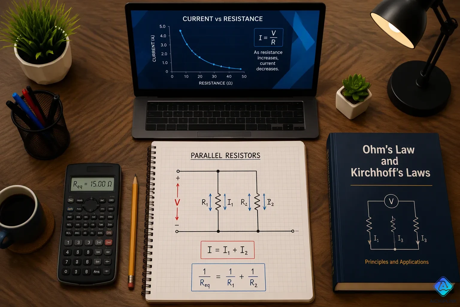
This section answers one question: how does the current divider formula come from Ohm's Law and Kirchhoff's Current Law? Three things start the work. The first is the equal-voltage condition in a parallel circuit. The second is Ohm's Law itself. It links voltage, current, and resistance in each branch. The third is Kirchhoff's Current Law. It adds branch currents into the total. The derivation of the current divider formula then unfolds in clear steps, and each step builds on the last. A worked example tests the result with KCL. Current Divider Circuits reward this careful approach, and the current divider becomes easy to trust.
Key Takeaways
-
Parallel branches have the same voltage. This equal voltage makes the analysis easier.
-
Ohm's Law says you find each branch's current by dividing the voltage by the resistance.
-
Kirchhoff's Current Law puts the branch currents together to get the total current.
-
The two-resistor current divider formula puts the other resistor's resistance on top.
-
If there are more than two branches, use the conductance form of the current divider formula.
Parallel Circuit Setup for Current Dividers
Equal-Voltage Condition
A parallel circuit hooks up every branch across the same two nodes. This setup makes the voltage across each branch the same, so V1 = V2 is true for two parallel resistors. The same rule works for any number of resistors in parallel: VR1 = VR2 = VR3, and so on. This shared voltage is the first piece in deriving the current divider formula.
The equal-voltage condition cuts out a step in the analysis. Each branch current comes straight from Ohm's Law as I = V/R, and you don't need to find an individual voltage drop first. That shortcut is what makes current divider circuits so easy to handle, and it is why the current divider works at all. This condition is the base for current divider circuits, and it shows how analyzing parallel circuits and splitting current into branch shares works. The table below shows common supply values used in worked examples of current division.
| Example | Circuit configuration | Voltage value |
|---|---|---|
| Two-branch divider | 20 Ω resistor in parallel with 60 Ω resistor | 30 V supply |
| Multi-branch divider | 10 kΩ, 4 kΩ, and 2 kΩ resistors in parallel | 100 V source |
Total and Branch Currents
Kirchhoff's Current Law rules the junction where the branches meet. The law says the algebraic sum of currents entering and leaving a node equals zero at every instant. Charge cannot build up at an ideal junction, so every unit of charge flowing in must flow out through one or more paths. In a parallel circuit, the total current IT entering the node equals the sum of the branch currents leaving it: IT = I1 + I2. This is true for two resistors in parallel and for any larger group of resistors in parallel.
This relationship gives the second piece for the current divider. The source current splits among the branches, and each branch current carries a share of the total. A water-pipe analogy makes the idea clear: the amount of water entering a junction equals the amount leaving. The current divider rule answers this current division question, and the split depends on the resistance of each path. Lower resistance carries a larger share of the current in parallel resistors.
Step-by-Step Derivation from Ohm's Law and Kirchhoff's Current Law
Ohm's Law per Branch
Ohm's Law says voltage equals current times resistance, or V = I × R. If you rearrange it, you get I = V / R. Each branch of a parallel circuit follows this rule on its own. The shared node voltage pushes every branch, so each branch current equals that common voltage divided by its own resistance. A 9 V source across three parallel resistors shows the pattern clearly:
-
Branch R1 at 10 kΩ: I_R1 = 9 V / 10 kΩ = 0.9 mA
-
Branch R2 at 2 kΩ: I_R2 = 9 V / 2 kΩ = 4.5 mA
-
Branch R3 at 1 kΩ: I_R3 = 9 V / 1 kΩ = 9 mA
The same logic works at any size. A 5 V source across a 100 Ω branch and a 200 Ω branch gives 50 mA and 25 mA. So Ohm's Law writes every branch current using one shared voltage and one individual resistance. Since V1 = V2 in a parallel circuit, the products I1 × R1 and I2 × R2 must be equal. That equality, I1 × R1 = I2 × R2, links the two branch currents directly and sets up the algebra that follows.
Kirchhoff's Current Law and Solving
Kirchhoff's Current Law (KCL) says the total current entering a node equals the sum of the currents leaving it. For two branches, KCL gives IT = I1 + I2. Putting Ohm's Law into each term gives IT = V/R1 + V/R2. Factoring out the common voltage gives IT = V × (1/R1 + 1/R2). Solving for V gives V = IT / (1/R1 + 1/R2), which is the total current times the parallel equivalent resistance.
The last step isolates each branch current. Putting V back into I1 = V/R1 gives I1 = IT × (1/R1) / (1/R1 + 1/R2). Multiplying the top and bottom by R1 × R2 simplifies this to I1 = IT × R2 / (R1 + R2). The same substitution for I2 gives I2 = IT × R1 / (R1 + R2). This is the current divider formula in its two-resistor form.
The derivation from Ohm's Law and Kirchhoff's Current Law is one continuous chain: equal voltage, Ohm's Law per branch, KCL at the node, then algebraic solving. No step relies on a shortcut. The current divider rule follows directly from these two fundamental laws. The derivation of the current divider formula confirms that the current divider comes from conservation of charge and the voltage-current relation, not a separate principle. Readers who trace ohm's law + KCL through this sequence see exactly why the current divider formula takes the form it does. The current division formula also explains how branch current relates to total current through the resistance ratio.
Two-Resistor Form and N-Branch Generalization
Two-Resistor Current Divider Formula
The math from the last section gives two clean results for resistors R1 and R2 in parallel with total current IT. The two-resistor current divider formula looks like this:
-
I1 = IT × R2 / (R1 + R2)
-
I2 = IT × R1 / (R1 + R2)
Look at which resistor is on top in each fraction. The current through R1 depends on R2, and the current through R2 depends on R1. This "other resistor" setup is the special mark of the two-resistor current divider, and it confuses many readers at first.
The ratio idea makes the pattern easy to remember. Dividing one equation by the other gives I1 / I2 = R2 / R1. The ratio of the branch currents equals the inverse ratio of the resistances. A branch with half the resistance of its neighbor carries twice the current. The total-to-individual resistance ratio equals the individual-to-total current ratio, so the current divider rule always favors the smaller resistor. This inverse relationship is the heart of every current divider, and it explains why parallel resistors share current unevenly.
Generalizing with Conductance
Circuits with three or more branches need a more flexible tool. Conductance, defined as G = 1/R, makes the n-branch current divider formula simple. The current through any branch n equals the total current times that branch's conductance divided by the sum of all branch conductances: In = IT × Gn / Gtotal.
This conductance form works well at any size. Doubling a branch's conductance doubles its share of the current. The n-branch current divider therefore treats every path the same way, whether the circuit holds two branches or twenty. The current division formula in conductance form also matches what we expect in real life. Wider PCB traces have lower resistance and higher conductance, so they carry more current in proportion when placed in parallel. The current divider rule in this shape needs no special case for the two-resistor current divider; the general form shrinks to it when only two branches exist.
The current divider formula thus has two faces. The resistance form suits quick hand calculations on two branches. The conductance form suits larger networks and design work. Both come from the same derivation chain, and both give the same answers. Engineers who master the current divider in both forms can analyze current divider circuits of any size with confidence.
Worked Example and KCL Verification
Numerical Example
A real example shows how the current divider formula works. A source sends 6 A into two parallel resistors. R1 is 100 Ω and R2 is 200 Ω. The two-resistor current divider gives the branch current for each path.
The current through R1 equals the total current times R2 divided by the sum of both resistances: 6 A × 200 Ω / 300 Ω = 4 A. The current through R2 equals the total current times R1 divided by the same sum: 6 A × 100 Ω / 300 Ω = 2 A. These current divider formula examples show the inverse pattern clearly. R1 is half of R2, so it carries double the current. The current in parallel resistors always follows this rule.
| Parameter | Value |
|---|---|
| Total current (IT) | 6 A |
| R1 | 100 Ω |
| R2 | 200 Ω |
| I1 (through R1) | 4 A |
| I2 (through R2) | 2 A |
Verifying with KCL
Kirchhoff's Current Law gives a fast way to check any result. The law says the total current entering a node equals the sum of the currents leaving it. Here the branch currents add up to 4 A + 2 A = 6 A. That sum matches the total current exactly, so the answer passes the KCL test.
This check takes almost no time and catches most math mistakes. Anyone who uses the current divider rule on two parallel resistors can always confirm the result this way. The current divider formula and KCL work as a team: one predicts the split, and the other proves it.
A quick comparison with the voltage divider helps lock in the form. The voltage divider multiplies the total voltage by the resistance of the part you want over the total resistance. The current divider multiplies the total current by the other resistance over the total. That swapped spot is the main difference, and it keeps current division and voltage division from getting mixed up.
The derivation chain is short. First comes equal voltage across parallel branches. Ohm's Law gives each branch current. Kirchhoff's Current Law gives the total. Algebra finishes the job. For two resistors, the current divider formula reads I1 = IT × R2 / (R1 + R2). In conductance form, Ix = IT × Gx / sum of G. Readers should re-derive it once themselves. Ohm's law and KCL then confirm the result, since the parts must sum to the total. The current divider rule also differs from the voltage divider. The current divider uses the opposite resistance on top. That contrast keeps the current divider formula straight.

Written by Jack Elliott from AIChipLink.
AIChipLink, one of the fastest-growing global independent electronic components distributors in the world, offers millions of products from thousands of manufacturers, and many of our in-stock parts is available to ship same day.
We mainly source and distribute integrated circuit (IC) products of brands such as Broadcom, Microchip, Texas Instruments, Infineon, NXP, Analog Devices, Qualcomm, Intel, etc., which are widely used in communication & network, telecom, industrial control, new energy and automotive electronics.
Empowered by AI, Linked to the Future. Get started on AIChipLink and submit your RFQ online today!
Frequently Asked Questions
Why does the smaller resistor carry more current in a parallel circuit?
Both branches get the same voltage. Ohm's Law then gives each branch current as voltage divided by resistance. A smaller resistance makes a larger current. This opposite pattern is the main idea behind every current divider.
Does the current divider formula work for more than two resistors?
The two-resistor form does not stretch directly. Readers should switch to the conductance form instead. Each branch current equals the total current times that branch's conductance divided by the sum of all conductances. This version handles any number of parallel branches.
How can someone check a current divider answer quickly?
Kirchhoff's Current Law gives a fast check. The branch currents must add up to the total current entering the node. In the article's example, 4 A plus 2 A equals 6 A. A matching sum confirms the current divider result.
What is the difference between the current divider rule and the voltage divider rule?
The voltage divider multiplies total voltage by the resistance of the part over the total resistance. The current divider rule multiplies total current by the other resistance over the total. That swapped spot shows how parallel branches share current in reverse with resistance.
Why does the derivation need Kirchhoff's Current Law at all?
Ohm's Law alone describes each branch. Kirchhoff's Current Law links the branches by tying them to the total current. Without that link, no one can state a branch current in terms of the total. The current divider needs both laws working together.