Here is a mistake that happens in fiber installations more often than anyone in the industry likes to admit: a technician installs a brand-new SC/APC connector from the fiber distribution network and connects it to a patch panel port terminated with SC/UPC. The connector clicks in, the fiber link appears to be live, but insertion loss is 3–4 dB higher than specified and the link margin is gone before the first packet is sent. No alarm fires. No error message explains the problem. The link simply underperforms, and it will continue to underperform until someone with a fiber scope inspects the connection and discovers that an angled-polish ferrule has been mated with a flat-polish ferrule — a category mismatch that no amount of cleaning will fix.
That specific failure comes from not understanding one dimension of fiber connector selection: the end-face polish type. But there are three dimensions to get right, and getting any one of them wrong in the wrong context ranges from a minor nuisance to a link that cannot be commissioned at all.
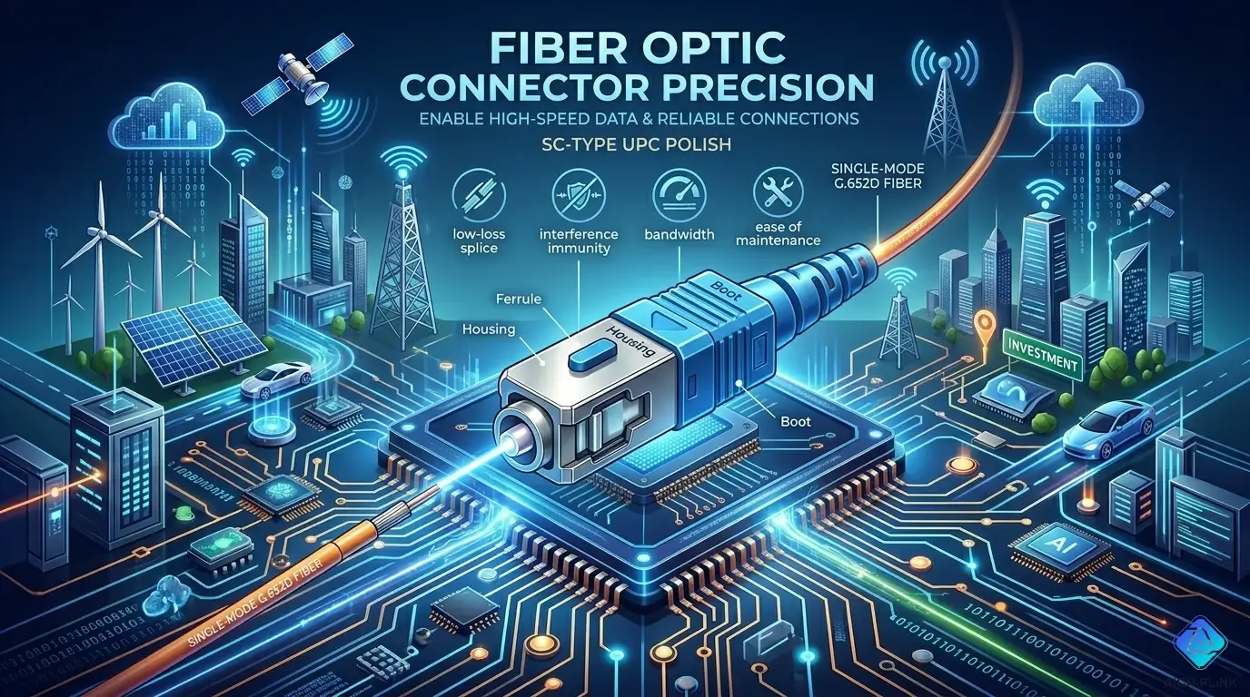
This guide gives you a complete framework for selecting fiber optic connectors — from the six connector body types you will encounter in the field, through the three polish specifications that define signal integrity, to the practical decision flowchart that tells you which combination is correct for your application.
1.0 Three Questions to Answer Before Specifying Any Fiber Connector
Most selection errors happen because engineers jump directly to connector body type (LC vs SC vs MPO) without first establishing the constraints that make one choice correct and others wrong. Answer these three questions first.
Question 1: What fiber type and transmission distance are you working with?
Single-mode fiber (SMF, 9/125 μm core) is used for distances beyond roughly 300 meters and all DWDM and CATV applications. Multimode fiber (MMF, 50 or 62.5 μm core) is used for shorter links within buildings and campuses, typically up to 300–400 meters for OM4 at 10Gbps. While most connector body types work with both fiber types (the connector body type and fiber type are independent specifications), the polish type is critically different: single-mode links with return-loss sensitivity almost always require APC polish; multimode links almost always use UPC or flat PC polish.
Question 2: What is the port density requirement and form factor constraint?
A 1U patch panel holds 24 SC ports in duplex configuration (12 duplex connections). The same 1U panel holds 48 LC ports in duplex configuration — double the density for the same rack space. If you are designing a data center where rack space costs money and fiber counts are high, the choice between SC and LC is not a performance question, it is a density and economics question. For 40G, 100G, 400G, and 800G applications using parallel optic transceivers (QSFP28, QSFP-DD, OSFP), MPO/MTP connectors carrying 8, 12, or 24 fibers in a single connector are not optional — they are required by the transceiver's optical interface specification.
Question 3: What is the mechanical environment?
Standard fiber connectors (LC, SC) in controlled indoor environments (data centers, office telecommunications rooms) use push-pull or latch mechanisms that are appropriate for clean, stable installations. High-vibration environments (industrial automation, rail, military, marine) require connectors that cannot vibrate loose — either FC (threaded) or ruggedized versions of LC/SC with locking sleeves. Outdoor or harsh environments require IP-rated enclosures or connectors with environmental sealing. This question is often skipped in design specifications and causes failures only after installation, when a connector in a vibrating enclosure begins introducing intermittent loss events.
2.0 The Six Connector Body Types — What Each One Is and Where It Belongs
[Insert image: side-by-side photos of LC SC FC ST MPO and E2000 fiber optic connectors showing relative size comparison with ferrule diameter labels and coupling mechanism type labeled for each — alt: six fiber optic connector types side by side comparison showing LC 1.25mm latch SC 2.5mm push-pull FC 2.5mm screw ST 2.5mm bayonet MPO multi-fiber array and E2000 snap-shut dust cap with relative size scale]
LC (Lucent Connector) — the current standard for data centers and enterprise
The LC uses a 1.25 mm ceramic ferrule and a latch mechanism (similar in feel to an RJ45 tab). It is the smallest of the common single-fiber connector types, occupying roughly half the face area of an SC. LC is the dominant connector for SFP, SFP+, and SFP28 transceivers (1G, 10G, 25G), making it the de-facto standard for any switch, router, or server with SFP ports. LC duplex connectors (two fibers in a clip-together housing) occupy the same faceplate footprint as an RJ45 port — a convenient coincidence that helped drive adoption in structured cabling.
Insertion loss: typically ≤ 0.3 dB (UPC), ≤ 0.5 dB (APC). Return loss: ≥ 50 dB (UPC), ≥ 60 dB (APC).
SC (Subscriber/Square Connector) — the reliable workhorse of telecom
The SC uses a 2.5 mm ceramic ferrule and a push-pull coupling mechanism with a square plastic body that snaps into an adapter with a satisfying click. SC was the dominant fiber connector in the 1990s and early 2000s and remains very common in telecom infrastructure, FTTH (Fiber to the Home) OLT/ONT connections, CATV, and test equipment. It is easier to handle than LC in field-termination scenarios (larger body = easier to grip, especially with gloves), and the push-pull mechanism has a non-optical disconnect feature — pulling the connector pulls the body, not the fiber. SC is being displaced by LC in high-density data center applications but remains the right choice for FTTH, telecom distribution, and applications where per-port density is not the primary constraint.
Insertion loss: typically ≤ 0.3 dB (UPC), ≤ 0.4 dB (APC). Return loss: ≥ 50 dB (UPC), ≥ 60 dB (APC).
FC (Ferrule Connector / Fiber Channel) — for vibration, precision, and legacy test equipment
The FC uses a 2.5 mm ceramic ferrule in a threaded screw-on metal housing, providing the most secure mechanical connection of any common fiber connector. This threading resistance to vibration and accidental disconnection makes FC the standard for: optical spectrum analyzers, OTDRs, and other test instruments; high-vibration industrial environments; and applications where accidental pull-out would cause a system fault. The threading also means connection and disconnection is slower (several rotations required), making FC unsuitable for high-density patch environments where connectors are frequently changed. FC is declining in new installations but remains present in test labs and industrial facilities.
Note: FC connectors have two incompatible key widths (2.0 mm and 2.14 mm) for polarization-maintaining variants — verify compatibility before ordering.
Insertion loss: typically ≤ 0.3 dB. Return loss: ≥ 50 dB (UPC), ≥ 60 dB (APC).
ST (Straight Tip) — the legacy enterprise connector still found in older buildings
The ST uses a 2.5 mm ferrule in a spring-loaded bayonet twist-lock housing (similar to a BNC connector). ST was developed by AT&T and dominated 1980s and 1990s enterprise LANs, campus fiber, and military networks. It remains installed in many older buildings and educational institutions. ST is almost never specified for new designs — LC and SC have entirely supplanted it — but installers still encounter it during maintenance and upgrades of legacy systems. ST requires half a turn to lock/unlock, which can be awkward in high-density patch environments.
Insertion loss: typically ≤ 0.5 dB. Return loss: ≥ 45 dB.
MPO/MTP (Multi-fiber Push On / Multi-fiber Termination Push On) — for parallel optics and high-speed data centers
MPO is a multi-fiber connector housing a rectangular ferrule that aligns multiple fiber cores simultaneously — typically 8, 12, or 24 fibers in a single connector body. MTP is US Conec's proprietary enhanced version of MPO with improved alignment pins, tighter manufacturing tolerances, and a removable housing that allows field re-polishing and gender changes. MTP and MPO are physically intermateable.
MPO/MTP connectors are mandatory for 40G (4×10G, using 8-fiber MPO), 100G (4×25G using 8-fiber MPO or 2×50G using 8-fiber MPO), and 400G (8×50G using 16-fiber or 4×100G using 8-fiber MPO) applications using parallel-optic QSFP28, QSFP-DD, and OSFP transceivers. A single 12-fiber MPO connector replaces 6 LC duplex connectors — dramatically reducing connector count, cable clutter, and installation time in high-density backbone cabling.
Critical detail: MPO connectors have a key orientation (key-up or key-down) that determines polarity. Incorrect key orientation swaps TX and RX fibers and breaks the link. Always verify polarity type (Type A, B, or C) before ordering MPO patch cords and cassettes.
Insertion loss: typically ≤ 0.6 dB per connector (IEC standard), ≤ 0.35 dB (MTP elite grade).
E2000 (LC Push-Pull with dust-cap shutter) — for telecom and CATV with contamination control
Less common outside Europe and telecom, the E2000 uses a 1.25 mm ferrule in a snap-in housing with an integral spring-loaded dust shutter that closes automatically when the connector is unmated. This prevents contamination of the ferrule end-face without requiring a dust cap to be installed manually — important in environments where connectors are frequently mated/unmated and contamination risk is high. Used primarily in CATV distribution, DWDM systems, and European telecom deployments.
3.0 PC, UPC, and APC: The Polish Type Determines Signal Integrity
The connector body type tells you the physical form factor. The polish type tells you how the fiber end-face is finished — and this determines return loss, which in turn determines whether your link works correctly in return-loss-sensitive applications.
PC (Physical Contact) — flat polish, lowest performance, rarely used in new installations
The fiber end is polished flat. When mated, the two flat faces press together. Air gaps and surface irregularities cause back-reflections. Return loss: approximately 40 dB. PC polish is the oldest standard and is rarely specified for new installations except in very-low-cost or low-performance applications.
UPC (Ultra Physical Contact) — slightly convex polish, standard for most digital applications
The fiber end is polished with a slight convex curve (the apex centered on the fiber core). When mated, the fiber cores make direct contact at the center of the convex surface, minimizing air gaps. Return loss: ≥ 50 dB. UPC is the standard polish for multimode fiber, most enterprise single-mode data applications (10G, 25G, 100G Ethernet), and any application where return loss ≥ 50 dB is sufficient. UPC connectors typically have a blue housing (single-mode) or beige/black housing (multimode).
APC (Angled Physical Contact) — 8° angled polish, required for return-loss-sensitive applications
The fiber end is polished at an 8° angle. When mated, reflected light leaves the fiber core at an angle and is absorbed by the cladding instead of traveling back up the fiber. Return loss: ≥ 60 dB — at least 10 dB better than UPC, and often 65–70 dB in practice. APC is required for: CATV/FTTH/PON networks (where reflected light interacts with laser sources), DWDM systems (where back-reflections cause crosstalk between channels), coherent optical systems, and any application where the laser source's performance is degraded by back-reflected light. APC connectors have a green housing to distinguish them from UPC. APC connectors must only be mated with other APC connectors. Mating APC with UPC causes approximately 3–4 dB insertion loss and destroys the return loss advantage — exactly the failure scenario described in this article's opening.
Polishing type summary:
| Polish | End-face geometry | Return loss | Housing color | Typical use |
|---|---|---|---|---|
| PC | Flat | ~40 dB | Various | Legacy only |
| UPC | Slightly convex | ≥50 dB | Blue (SM) / Beige/Black (MM) | Data, enterprise, most digital |
| APC | 8° angle | ≥60 dB | Green | CATV, PON, FTTH, DWDM, coherent |
4.0 Comparison Matrix: All Major Connector Types Side by Side
| Parameter | LC | SC | FC | ST | MPO/MTP |
|---|---|---|---|---|---|
| Ferrule diameter | 1.25 mm | 2.5 mm | 2.5 mm | 2.5 mm | Rectangular array |
| Fiber count | 1 (simplex/duplex) | 1 (simplex/duplex) | 1 | 1 | 8 / 12 / 24 |
| Coupling mechanism | Latch (push-pull) | Push-pull snap | Threaded screw | Bayonet twist-lock | Push-on keyed |
| Relative size | Smallest | Medium | Medium | Medium | Largest body |
| Density (per 1U panel) | 48 ports (duplex) | 24 ports (duplex) | 24 ports | 24 ports | Varies (12-fiber × N) |
| Insertion loss (typical) | ≤ 0.3 dB | ≤ 0.3 dB | ≤ 0.3 dB | ≤ 0.5 dB | ≤ 0.6 dB (0.35 MTP elite) |
| Mating cycles | 500–1,000 | 500–1,000 | 500–1,000 | 500–1,000 | 500–1,000 |
| Vibration resistance | Low | Low | High (threaded) | Medium | Low–Medium |
| Cost (relative) | Low-medium | Lowest | Medium-high | Low | High per connector, low per fiber |
| Primary applications | Data centers, SFP, enterprise | Telecom, FTTH, CATV, test | Industrial, test equipment | Legacy enterprise | 40G/100G/400G parallel optics |
| Polish types available | UPC, APC | UPC, APC | UPC, APC | PC, UPC | UPC, APC |
| Status | Current standard | Current (telecom) | Declining (niche) | Legacy | Current (high density) |
5.0 The Per-Fiber Cost Calculation: When MPO/MTP Makes Economic Sense
MPO/MTP patch cables cost significantly more per assembly than LC or SC patch cables. A single 12-fiber MPO/MTP cable might cost $30–80, while a single LC duplex patch cable costs $3–15. The mistake is comparing assembly cost rather than per-fiber cost.
Scenario: Connecting 48 fiber ports between two racks
Option A — LC duplex patch cables:
- 24 LC duplex cables (each carrying 2 fibers = 48 total fibers)
- Cost: 24 × $8 = $192
- Connector count at each end: 24 duplex = 48 connector faces per rack face
- Time to install: ~30 seconds per cable × 24 cables = ~12 minutes
Option B — MPO-12 to LC fan-out cassettes + MPO trunk cables:
- 4 × MPO-12 trunk cables (each carries 12 fibers = 48 total fibers)
- 4 × MPO-12 cassettes with LC duplex breakout (8 LC ports each = 32 LC ports for 4 cassettes... adjusting: each 12-fiber MPO cassette provides 6 LC duplex ports = 4 cassettes provide 24 LC duplex ports = 48 fibers)
- Cost: 4 MPO trunks × $45 = $180 + 4 cassettes × $60 = $240 → Total: $420
- Time to install: install 4 cassettes + plug in 4 MPO trunks ≈ 5 minutes
At first glance Option B costs 2× more. But consider:
- Cable management: 4 MPO trunks vs 24 LC cables — dramatically less cable bulk in trays
- Future-proofing: MPO infrastructure is ready for 40G/100G/400G transceiver upgrades by swapping cassette types
- Per-fiber cost at scale: At 480 fibers (10× larger installation), MPO infrastructure cost scales more favorably than LC patch cable bulk
Rule of thumb: For fiber counts above 24 fibers between two points, MPO/MTP infrastructure is worth evaluating on per-fiber cost. For small installations (< 24 fibers), LC or SC direct patch cables are simpler and less expensive.
6.0 ⚠️ Four Field-Killing Mistakes in Fiber Connector Selection
Mistake 1: Mating APC with UPC connectors (the most common link-killer)
As described in this article's opening: APC connectors (green housing, 8° angled face) must only be mated with other APC connectors. Mating APC with UPC causes approximately 3–4 dB of additional insertion loss because the angled face creates a gap and misalignment when pressed against a flat or convex UPC face. In a link with 3 dB margin, this single mismatch consumes all available margin and may prevent the link from achieving BER targets. The fix is trivial once identified — replace the mismatched connector — but diagnosing the cause typically requires a fiber inspection scope, which many installers do not carry. Prevention: color-code your infrastructure, train installers on green=APC, and include APC/UPC verification in commissioning checklists.
Mistake 2: Ignoring MPO polarity in 40G/100G/400G deployments
MPO connectors have 12 fibers arrayed in a row. The polarity convention — which fiber goes to which port when the connector is plugged in — depends on the key orientation (key-up or key-down) and the polarity type (IEC Type A: straight-through; Type B: reversed; Type C: pair-flipped). Modern parallel-optic transceivers specify their TX/RX polarity requirements. If the MPO cable assembly does not match the required polarity, TX pairs are connected to TX pairs instead of TX-to-RX, and no light arrives at the receiver. This failure produces no optical signal at all — not a degraded signal, but zero. It looks identical to a broken cable until polarity is checked. Prevention: document your polarity plan before ordering cables and cassettes, and test polarity during commissioning before systems are live.
Mistake 3: Selecting connectors without specifying the polish type for the application
Ordering "SC connectors" without specifying UPC or APC is like ordering "cable" without specifying copper or fiber. In a CATV or PON (Passive Optical Network) deployment, a UPC connector where APC is required causes approximately 10–20 dB worse return loss, which interacts with the laser source in the OLT and can cause instability, bit errors, and even oscillation in the transmitter laser. In a data center 10G Ethernet link, APC where UPC is required wastes money (APC costs more) and provides no benefit since the application does not require the superior return loss. Specify the full connector designation — SC/APC, LC/UPC, FC/UPC — never just the body type alone.
Mistake 4: Reusing existing connector infrastructure for higher data rates without recertifying
A fiber link installed for 1G Ethernet with SC/PC connectors may have 0.8 dB of insertion loss per connector pair — perfectly acceptable for 1G. When that link is repurposed for 10G, the same 0.8 dB loss may exceed the 10GBASE-SR loss budget, causing intermittent errors or no link at all. Fiber insertion loss budgets get tighter as data rates increase (shorter allowable attenuation budgets at higher speeds). Before reusing existing fiber infrastructure for higher speeds, certify the link with an OTDR or optical loss test set at the new speed's specified wavelength and loss budget. Never assume an existing link that worked at lower speeds will work at higher speeds without measurement.
7.0 Selection Checklist
Step 1 — Determine fiber type and application: ☐ Single-mode (9/125 μm) or multimode (50/125 OM3/OM4/OM5 or 62.5/125)? ☐ What transmission distance and data rate? ☐ Any return-loss-sensitive components in the link (laser, CATV, PON, DWDM, coherent)?
Step 2 — Determine polish type: ☐ CATV/PON/FTTH/DWDM/coherent → APC (green housing) ☐ Standard digital data (Ethernet, Fibre Channel) → UPC (blue housing for SM) ☐ Multimode → UPC or PC ☐ If unsure → default to UPC unless APC is required by the application
Step 3 — Determine connector body type: ☐ Data center / high-density rack / SFP transceivers → LC ☐ FTTH/CATV/telecom field distribution → SC ☐ High-vibration industrial / test equipment → FC ☐ Legacy multimode enterprise / campus → ST (maintenance only; do not specify for new) ☐ 40G / 100G / 400G / 800G parallel optics → MPO/MTP (mandatory for QSFP28, QSFP-DD, OSFP) ☐ European CATV / high-contamination environments → E2000
Step 4 — Verify compatibility and polarity: ☐ Confirm all connectors in the link use matching polish type (all APC or all UPC) ☐ For MPO links: document polarity type (IEC Type A/B/C) and verify throughout ☐ For FC: verify key width (2.0 mm or 2.14 mm) if polarization-maintaining fiber is involved
Step 5 — Inspect and test before commissioning: ☐ Inspect all ferrule end-faces with a fiber inspection scope before mating ☐ Clean with lint-free fiber cleaning tools before first insertion ☐ Certify link loss against the data rate's optical budget using an OTDR or OLTS ☐ For MPO: use an MPO-compatible inspection probe (standard probes cannot inspect arrayed ferrules)
8.0 Sourcing
Fiber optic connectors, patch cables, and MPO/MTP assemblies are available from authorized optical component distributors. Key suppliers include Corning, CommScope, Belden, FS.com, and Panduit for infrastructure-grade assemblies; for bare connector components and pigtails, Amphenol, Molex, and US Conec (MTP brand) are primary manufacturers.
For competitive pricing on LC, SC, FC, ST, and MPO/MTP patch cables and connectors with verified specifications, visit aichiplink.com.
9.0 Real Questions from Network Designers and Installers
Q: I have a 10GBASE-SR link using OM4 multimode fiber and LC/UPC connectors. The link works but the OTDR shows 0.5 dB loss per connector pair. Is this acceptable?
A: 10GBASE-SR (IEEE 802.3ae) specifies a maximum channel insertion loss of 2.6 dB for OM4 fiber. If you have two connector pairs (one at each end of the link) at 0.5 dB each, that is 1.0 dB of connector loss. Add the fiber loss (OM4 at 850 nm: ~3.0 dB/km, so at 100m: ~0.3 dB) and any splice loss. Total ≤ 2.6 dB is required. At 0.5 dB per connector pair you have margin, but you are higher than the typical specification (≤ 0.3 dB per connector pair for UPC). Inspect the connectors — 0.5 dB often indicates contamination, physical damage to the ferrule, or misaligned cores. Clean both connectors with a fiber cleaning tool and re-measure. If loss persists above 0.3 dB after cleaning, the connector end-face may require re-polishing or replacement.
Q: Our data center is upgrading from 10G to 100G. We currently have LC duplex patch cables throughout. Do we need to replace everything?
A: Not necessarily, but it depends on your transceiver type. If you are using 100GBASE-SR4 (which uses QSFP28 with MPO-12 connectors and 4×25G parallel lanes), you cannot use existing LC duplex cables — the transceiver requires MPO, and you need to install MPO infrastructure. If you are using 100GBASE-LR4 or 100GBASE-SR (single-lane 100G options like QSFP28 100GBASE-SR), you can reuse existing LC duplex fiber infrastructure provided the link loss budget is met — certify the link with an OLTS before upgrading transceivers. The most common 100G path in data centers uses 100GBASE-SR4 (parallel optics), which requires MPO, so most 10G-to-100G upgrades involve installing MPO cassette panels and trunk cables while retaining LC connections to servers and switches that use single-lane 10G/25G SFPs.
Q: What does "Type A" vs "Type B" MPO polarity mean, and how do I know which one I need?
A: MPO polarity determines how fiber positions are mapped through the connector system. In a 12-fiber MPO: Type A (straight) passes fiber 1 at position 1 to position 1 at the other end, fiber 2 to 2, and so on — the fiber array is continuous. Type B (crossed) reverses the array — fiber 1 at one end connects to fiber 12 at the other. Type C (pair-flipped) reverses adjacent pairs.
The required type depends on your transceivers and equipment. For most data center applications using 40GBASE-SR4 and 100GBASE-SR4, the standard calls for a "method B" polarity scheme using Type B MPO trunks, which ensures TX and RX pairs are correctly crossed. Check your transceiver manufacturer's cabling guide — it will specify the required polarity method. When in doubt, buy pre-certified MPO assemblies labeled with their polarity type, and buy cassette modules from the same manufacturer as your trunk cables to ensure compatibility.
Q: Is there any reason to choose SC over LC for a new enterprise LAN installation in 2025?
A: In most cases, LC is the better choice for a new enterprise LAN installation because LC is the interface on all modern SFP/SFP+/SFP28 transceivers (1G/10G/25G), doubles port density on patch panels compared to SC, and provides the same optical performance at equivalent cost. The main reasons to choose SC in a new installation are: (1) You are deploying FTTH/PON infrastructure where the OLT and ONT equipment uses SC ports — many residential and CATV-grade PON devices are SC/APC; (2) You have existing SC infrastructure that you are extending and want a uniform connector type throughout; (3) Field technicians working outdoors or in difficult access points find SC easier to handle with gloves than the smaller LC. Outside these scenarios, LC is the right default choice for new enterprise installations.
10.0 Quick Reference Card
[Insert image: fiber optic connector types quick reference card showing LC SC FC ST MPO connector silhouettes with ferrule diameters, polish type color coding green APC blue UPC, insertion loss specs, and selection decision flowchart — alt: fiber optic connector quick reference card showing LC 1.25mm latch SC 2.5mm push-pull FC threaded ST bayonet MPO multi-fiber connector silhouettes with ferrule sizes polish type color coding and application decision guide]
Connector Body Type Summary:
| Connector | Ferrule | Coupling | Port density (1U duplex) | Best for |
|---|---|---|---|---|
| LC | 1.25 mm | Latch | 48 ports | Data centers, SFP, enterprise |
| SC | 2.5 mm | Push-pull | 24 ports | Telecom, FTTH/PON, CATV |
| FC | 2.5 mm | Threaded | 24 ports | Industrial, test equipment |
| ST | 2.5 mm | Bayonet | 24 ports | Legacy only (do not specify new) |
| MPO/MTP | Rectangular array | Push-on keyed | 12–24 fibers/connector | 40G/100G/400G parallel optics |
Polish Type = Housing Color:
| Color | Polish | Return loss | Use when |
|---|---|---|---|
| Green | APC | ≥ 60 dB | CATV, PON, FTTH, DWDM, coherent |
| Blue (SM) | UPC | ≥ 50 dB | Data, Ethernet, enterprise |
| Beige/Black (MM) | UPC or PC | ≥ 45–50 dB | Multimode applications |
Golden Rule: Green (APC) only mates with green (APC). Blue (UPC) only mates with blue (UPC). Mixing them causes 3–4 dB excess insertion loss.
One-line Decision Guide:
- SFP/SFP+ port or high-density rack → LC/UPC
- FTTH/PON/CATV connection → SC/APC
- Vibrating or industrial environment → FC/UPC or FC/APC
- 40G/100G/400G parallel transceiver → MPO-12 or MPO-8, verify polarity type
- Legacy multimode network (maintenance) → ST/PC or ST/UPC, whatever is already installed
For sourcing LC, SC, FC, MPO/MTP patch cables and fiber optic connector components with competitive pricing and verified specifications, visit aichiplink.com.

Written by Jack Elliott from AIChipLink.
AIChipLink, one of the fastest-growing global independent electronic components distributors in the world, offers millions of products from thousands of manufacturers, and many of our in-stock parts is available to ship same day.
We mainly source and distribute integrated circuit (IC) products of brands such as Broadcom, Microchip, Texas Instruments, Infineon, NXP, Analog Devices, Qualcomm, Intel, etc., which are widely used in communication & network, telecom, industrial control, new energy and automotive electronics.
Empowered by AI, Linked to the Future. Get started on AIChipLink.com and submit your RFQ online today!
Frequently Asked Questions
What is the most common fiber optic connector used today?
The LC connector is the most widely used in modern networks due to its small 1.25 mm ferrule and high port density, making it ideal for data centers and SFP-based equipment.
What is the difference between APC and UPC connectors?
APC connectors use an 8° angled polish (green) with ≥60 dB return loss for sensitive applications like PON and CATV, while UPC connectors use a flat/convex polish (blue) with ≥50 dB return loss for standard data networking. They must never be mixed.
When should I use MPO/MTP connectors?
MPO/MTP connectors are required for high-speed parallel optics such as 40G, 100G, and 400G networks, where multiple fibers (8/12/24) are transmitted through a single connector.
Is SC still used in modern fiber networks?
Yes, SC connectors are still widely used in telecom, FTTH, and CATV due to their durability and ease of use, although LC has largely replaced them in high-density environments.
How do I choose the right fiber optic connector?
Start by identifying fiber type (single-mode or multimode), then select the correct polish (APC or UPC), and finally choose the connector type (LC, SC, MPO, etc.) based on density, speed, and application requirements.