Quick Answer: What is a Dry Solder Joint?
Simple Definition: A dry solder joint is a poor electrical connection where solder didn't properly bond to the metal surfaces, creating unreliable or intermittent connections.
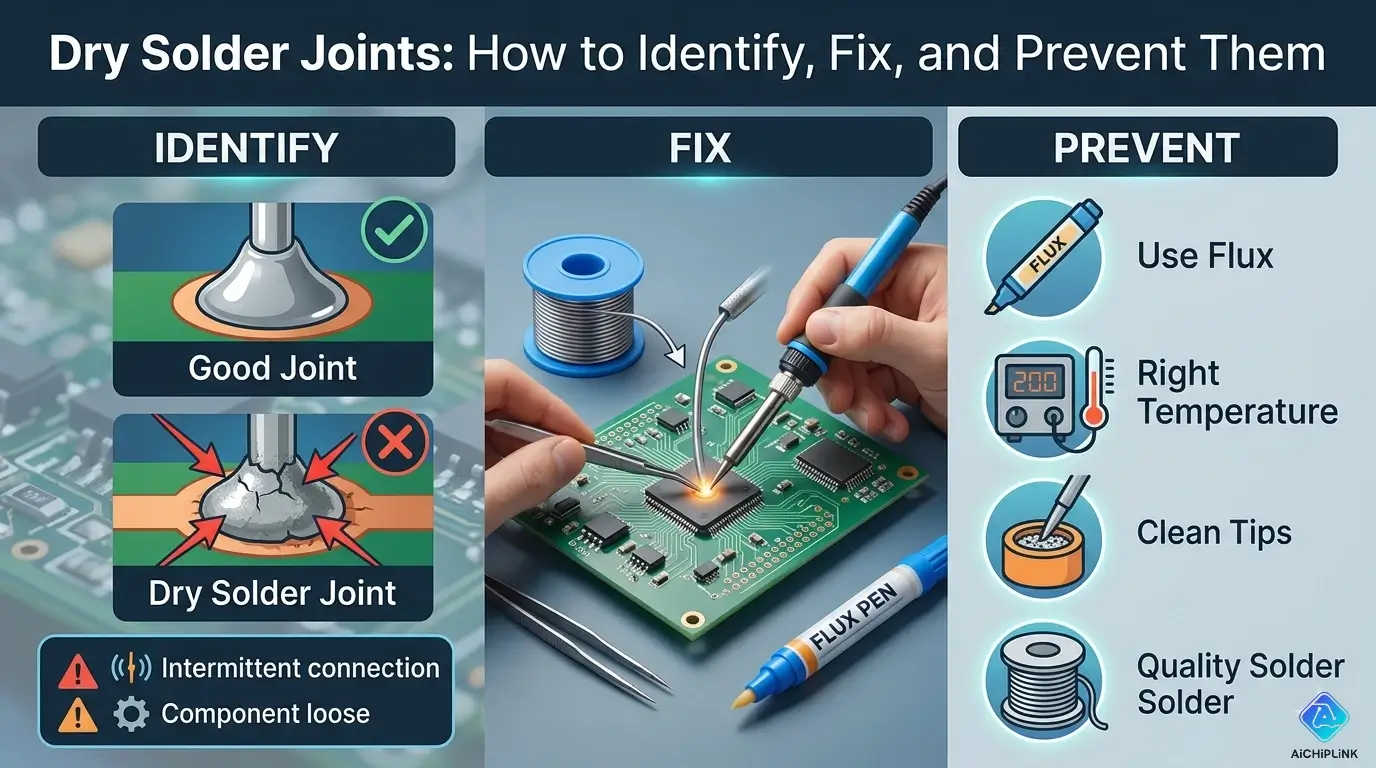
Visual Comparison:
| Good Solder Joint | Dry Solder Joint |
|---|---|
| Shiny, smooth surface | Dull, grainy appearance |
| Concave fillet shape | Lumpy, irregular shape |
| Complete coverage | Incomplete bonding |
| Strong mechanical bond | Weak, may crack easily |
Quick Test: Gently wiggle component lead. If it moves → dry joint!
Understanding Dry Solder Joints
What Makes a Joint "Dry"?
The Problem: Solder appears to be present, but didn't properly wet the metal surfaces.
Analogy:
Good Joint = Water droplet spreading on clean glass
Dry Joint = Water beading up on oily glass

The solder didn't "stick" properly!
Technical Explanation:
Good Joint:
Metal Surface + Flux + Heat → Clean oxide-free metal
Hot Solder contacts clean metal → Intermetallic bond forms
Result: Strong electrical AND mechanical connection

Dry Joint:
Metal Surface + Insufficient flux/heat → Oxide layer remains
Solder touches oxide layer → No intermetallic bond
Result: Weak connection that looks OK but fails
Common Causes
1. Insufficient Heat (Most Common)
Problem: Soldering iron not hot enough
Effect: Solder melts but doesn't flow
Temperature needed: 350-370°C (660-700°F)
If using <320°C → Guaranteed dry joints
2. Cold Joint (Moved During Cooling)
Problem: Component moved before solder solidified
Effect: Crystalline structure disrupted
Time to wait: 2-3 seconds after removing iron
3. Contaminated Surfaces
Problem: Oil, dirt, or oxidation on leads
Effect: Solder can't wet the surface
Prevention: Clean with isopropyl alcohol before soldering
4. Insufficient Flux
Problem: Not enough flux to remove oxides
Effect: Poor solder wetting
Solution: Use flux-core solder + extra flux paste
5. Wrong Solder Type
Problem: Lead-free solder requires higher temperature
Lead-free melting point: 217°C (422°F)
Leaded solder: 183°C (361°F)
If iron set for leaded → dry joints with lead-free!
Identifying Dry Solder Joints
Visual Inspection
What to Look For:
Good Joint Characteristics:
✅ Shiny, reflective surface
✅ Smooth, flowing appearance
✅ Concave fillet (volcano shape)
✅ Complete coverage of pad and lead
✅ No cracks or gaps visible
Dry Joint Red Flags:
❌ Dull, matte finish (looks grainy)
❌ Lumpy, blobby appearance
❌ Convex shape (ball sitting on surface)
❌ Visible gap between solder and pad
❌ Cracks or fractures in solder
❌ Lead can be wiggled
Visual Comparison:
GOOD JOINT:          DRY JOINT:
    Lead                 Lead
     │                    │
   ╱─┴─╲               ▄▄█▄▄  ← Blob sitting on top
  ╱     ╲             ▓▓▓▓▓▓▓
 ▕       ▏            ▀▀▀▀▀▀▀
───────────           ─────────
    PCB                  PCB

Smooth cone          Rough ball
Testing Methods
Test 1: Visual + Magnification
Tools:
- Magnifying glass (5-10×)
- USB microscope (recommended)
- Good lighting

Look for:
- Cracks (even tiny ones)
- Separation between solder and surface
- Grainy texture
Test 2: Wiggle Test
Method:
1. Gently grasp component lead with tweezers
2. Try to wiggle side-to-side
3. Observe any movement

Result:
✅ No movement = Good joint
❌ Any movement = Dry/cold joint
Test 3: Continuity Test
Equipment: Multimeter (continuity mode)

Procedure:
1. Set meter to continuity (beep mode)
2. Touch probes to both sides of joint
3. Listen for solid beep

Interpretation:
✅ Continuous beep = Good connection
❌ Intermittent beep = Poor joint
❌ No beep = Open circuit

Advanced: Wiggle component while testing
If beep cuts in/out → Dry joint!
Test 4: Resistance Test
Equipment: Multimeter (resistance mode)

For wire/trace joints:
Expected: <0.1Ω (essentially 0Ω)
Dry joint: >1Ω or fluctuating reading

Measure while gently flexing PCB
Stable reading = Good
Jumping resistance = Bad
Test 5: Thermal Cycling (Advanced)
Method:
1. Heat joint with hot air gun (low setting)
2. Monitor continuity/resistance
3. Let cool, monitor again

Dry joint behavior:
- Connection improves when hot (thermal expansion)
- Fails when cold (contraction opens crack)

Good joint: Consistent regardless of temperature
Troubleshooting Flowchart
START: Suspect Dry Solder Joint
│
├─ Visual Inspection:
│  ├─ Shiny & smooth? → Probably OK, test further
│  └─ Dull & grainy? → Likely dry joint → Proceed
│
├─ Wiggle Test:
│  ├─ Lead moves? → Definitely dry joint → FIX
│  └─ Solid? → Continue testing
│
├─ Continuity Test:
│  ├─ Continuous beep? → Might be OK
│  └─ Intermittent? → Dry joint → FIX
│
└─ Resistance Test:
   ├─ Stable <0.1Ω? → Good joint ✅
   └─ High or fluctuating? → Dry joint → FIX
How to Fix Dry Solder Joints
Method 1: Simple Reflow (For Minor Issues)
When to Use: Joint looks questionable but component still seated properly
Steps:
1. Prepare Iron
Temperature: 370°C (700°F) for leaded
            390°C (735°F) for lead-free
Tip: Clean, tinned tip
2. Apply Fresh Flux
Apply flux paste to suspect joint
Use syringe for precision
Or: Flux pen
3. Reflow the Joint
1. Touch iron to joint (contact both pad and lead)
2. Wait 2-3 seconds for everything to heat
3. Joint should become shiny and flow
4. Remove iron
5. Keep component still for 3 seconds
4. Inspect
Check for:
✅ Shiny surface
✅ Smooth fillet
✅ Good wetting on pad
Method 2: Add More Solder (For Insufficient Solder)
When to Use: Not enough solder on joint
Steps:
1. Clean Existing Joint
Apply flux to joint
Touch iron to melt existing solder
Wipe tip on brass sponge (removes excess)
2. Add Fresh Solder
1. Heat joint with iron
2. Feed new solder to junction (where iron meets component)
3. Let solder flow around lead
4. Remove solder wire first
5. Remove iron 1 second later
6. Don't move component for 3 seconds
Amount:
Through-hole: Solder should form 45° fillet all around lead
SMD: Small dome covering entire pad
Method 3: Complete Re-Do (For Bad Joints)
When to Use: Joint is severely compromised, cracked, or contaminated
Steps:
1. Remove Old Solder
Using Desoldering Pump:
1. Heat joint until solder melts
2. Quickly place pump and trigger
3. Suction removes molten solder

Using Desoldering Wick/Braid:
1. Place braid on joint
2. Press iron on top of braid
3. Braid absorbs molten solder
4. Move to fresh section of braid
5. Repeat until solder removed
2. Clean the Area
1. Remove component if needed
2. Clean pad with isopropyl alcohol
3. Scrape pad gently if oxidized (careful!)
4. Dry completely
3. Re-solder Properly
1. Apply fresh flux to pad
2. Tin the pad (thin layer of solder)
3. Insert component
4. Heat pad and lead simultaneously
5. Apply solder to junction
6. Create proper fillet
7. Remove iron, hold still 3 seconds
Method 4: SMD Rework (Surface Mount)
Special Considerations:
SMD joints are tiny - needs different approach
Hot Air Rework:
Equipment: Hot air station
Temperature: 350°C air temperature
Nozzle: 3-5mm diameter

Procedure:
1. Apply flux to all pads
2. Heat area with hot air (circular motion)
3. Solder will reflow and become shiny
4. Remove heat
5. Let cool without touching
Soldering Iron Method:
1. Add flux
2. Drag soldering iron across pads
3. Extra solder on tip helps heat transfer
4. Solder will reflow and self-align
Prevention Strategies
Proper Soldering Technique
Temperature Control:
Lead-Free Solder:
- Iron temperature: 370-390°C (700-735°F)
- Dwell time: 3-4 seconds

Leaded Solder (63/37):
- Iron temperature: 350-370°C (660-700°F)
- Dwell time: 2-3 seconds

Too hot: >400°C damages components, lifts pads
Too cold: <320°C creates dry joints
Correct Heating Method:
WRONG:
Iron → Solder → Component
(Solder balls up, doesn't wet)

RIGHT:
Iron touches BOTH pad and lead → Heat transfers
Then add solder to junction (where all three meet)
Solder flows toward heat
The 3-Second Rule:
Step 1: Touch iron to joint (0 seconds)
Step 2: Wait for heat transfer (1-2 seconds)
Step 3: Apply solder (2-3 seconds)
Step 4: Remove iron (3 seconds)
Step 5: Don't move! (3-6 seconds total)

Moving before 6 seconds = Cold joint!
Surface Preparation
1. Clean Leads Before Soldering
For through-hole components:
- Wipe leads with isopropyl alcohol
- Use fine sandpaper if oxidized
- Tin leads if very oxidized

For PCB pads:
- Clean with alcohol
- Don't touch pads with fingers (oils!)
2. Use Adequate Flux
Flux removes oxides during soldering
Types:
- Rosin (mild, needs cleaning)
- No-clean (convenient)
- Water-soluble (strong, must clean after)

Apply: Before soldering, extra flux never hurts
3. Check Component Lead Condition
Oxidized leads (dark, tarnished):
→ Clean before soldering
→ Or tin them first

Fresh, shiny leads:
→ Ready to solder
Equipment Maintenance
Soldering Iron Care:
1. Temperature Calibration
Check: Use iron thermometer
Most irons run 20-30°C lower than setting

If reading 340°C but set to 370°C:
→ Increase setting to 400°C to compensate
2. Tip Maintenance
Every session:
1. Clean tip on brass wool (not wet sponge)
2. Tin tip before storing
3. Wipe and re-tin every few joints

Replace tip when:
- Pitted or corroded
- Not transferring heat well
- Black oxidation won't clean off
3. Proper Iron Selection
Too weak: <40W → Can't heat large joints
Too strong: >100W → Damages small components

General purpose: 60W adjustable station
SMD work: 40W with fine tip
Large connectors: 80-100W or use hot air
Environmental Factors
Workspace Conditions:
1. Humidity Control
Ideal: 30-50% relative humidity
Too dry (<20%): Static damage risk
Too humid (>70%): Oxidation accelerates

Use: Hygrometer to monitor
Consider: Dehumidifier if >65% regularly
2. Proper Lighting
Essential: See what you're doing!
Use: LED magnifying lamp (5-10× magnification)
Good lighting reveals dry joints immediately
3. Temperature Stability
Rapid temperature changes = condensation
Condensation = oxidation = dry joints

Avoid: Soldering cold components from outside
Wait: Let components reach room temperature
Common Scenarios & Solutions
Scenario 1: Entire PCB Has Dry Joints
Cause: Manufacturing defect or storage issue
Symptoms:
- Multiple joints look dull
- Widespread intermittent failures
- Recent old stock (long storage)
Solution:
1. Identify critical joints (power, signals)
2. Reflow systematically with flux
3. Consider full board reflow:
   - Hot air station across whole board
   - Or reflow oven (for bare PCBs)
Prevention:
If purchasing PCBs:
- Check manufacturing date
- Avoid boards >2 years old
- Store in low-humidity environment
Scenario 2: Cold Solder Joint (Moved During Cooling)
Cause: Component moved before solder solidified
Identification:
Appearance: Fractured, crystalline surface
Looks: Like cracked glass
Texture: Rough, not smooth
Fix:
Must completely redo:
1. Remove old solder
2. Clean thoroughly
3. Re-solder without movement
4. Use helping hands to hold component steady
Prevention:
- Use helping hands/fixture
- Wait full 5 seconds before releasing
- Don't bump the board while soldering
Scenario 3: Lead-Free Solder Dry Joints
Cause: Higher melting point requires more heat
Characteristics:
Lead-free is less forgiving:
- Narrower temperature window
- Requires 20-30°C higher temperature
- Less shiny even when good
- Doesn't flow as easily
Solution:
1. Increase iron temperature: 380-400°C
2. Use extra flux (essential for lead-free)
3. Longer dwell time: 4-5 seconds
4. High-quality lead-free solder (SAC305)
Identification:
Good lead-free joint:
- Still looks slightly grainy (normal!)
- Should be smooth and well-formed
- Strong mechanical bond

Don't confuse normal lead-free appearance with dry joint!
Scenario 4: SMD Tombstoning (One-End Lifted)
Cause: Uneven heating during reflow
Appearance:
     Component
        │
      ┌─┴┐
      │  │  ← Lifted end
      │  │
      └──┘
   ───────── Pad
      ║
   Solder on one end only
Fix:
1. Heat both pads with hot air simultaneously
2. Gently press component flat with tweezers
3. Remove heat while holding
4. Hold 5 seconds until solidified
Prevention:
- Heat both pads equally (hot air or two irons)
- Use solder paste with same amount each side
- Reflow oven profile: gradual heat ramp
Quality Assurance Checklist
After Soldering - Inspect Each Joint:
Visual Check:
☐ Shiny surface (or appropriately matte for lead-free)
☐ Smooth fillet all around lead
☐ No cracks visible
☐ Pad completely wetted
☐ Appropriate solder amount (not too much/little)

Physical Check:
☐ Component doesn't move when gently tugged
☐ Solder joint feels solid (not springy)

Electrical Check:
☐ Continuity test passes
☐ Resistance <0.1Ω
☐ No intermittent connection when flexed

Documentation:
☐ Doubtful joints marked for re-inspection
☐ Critical joints tested twice
Tools & Materials
Essential Tools:
1. Soldering Iron
Recommendation: Hakko FX-888D or similar
Features needed:
- Temperature control (300-450°C)
- 60W power minimum
- Quick heat-up
- Comfortable grip

Tips: Chisel tip (most versatile)
2. Inspection Tools
Must-have:
- Magnifying glass (5-10×) - $10
- LED work light - $15
- Multimeter with continuity - $20

Nice to have:
- USB microscope (50-200×) - $30-100
- Magnifying lamp with light - $40-80
3. Desoldering Tools
Basic:
- Desoldering pump (solder sucker) - $5-10
- Desoldering wick/braid - $5

Advanced:
- Desoldering gun - $100-300
- Hot air rework station - $50-200
Recommended Materials:
Solder:
For hobbyist/general:
- 63/37 leaded solder, 0.8mm, flux-core - $10/50g
- Kester 44 (rosin flux)

For professional (RoHS):
- SAC305 lead-free, 0.5mm, no-clean flux - $15/50g

Avoid: Cheap solder from unknown brands
Quality matters!
Flux:
Rosin flux paste: MG Chemicals 8341 - $10
Flux pen: Kester 951 - $8
No-clean flux: Kester 2331-ZX - $12

Apply: Before and during soldering
Cleaning:
- 99% Isopropyl alcohol - $5/bottle
- Lint-free wipes - $5/pack
- Brass wire sponge (not wet sponge!) - $5
- Cotton swabs - $2
Professional Tips
From Industry Experts:
Tip 1: The "Halo" Test
Good solder joint has tiny "halo" around pad
This is flux residue, proves flux was active

No halo = insufficient flux = dry joint risk
Tip 2: Sound of Good Soldering
Listen: Good solder makes "tsss" sound when flowing
This is flux activating

No sound = no flux action = problem
Tip 3: Solder Should Chase the Heat
When applying solder:
- Solder should flow TOWARD the iron
- Spreads eagerly, like water downhill
- Doesn't ball up

If solder balls up:
→ Surface not hot enough or contaminated
Tip 4: When in Doubt, Reflow
Questionable joint?
Add flux and reflow
Takes 10 seconds, prevents hours of troubleshooting
Tip 5: Document Everything
Take photos:
- Before repair
- After repair
- Close-up of critical joints

Why: Learn from your work, track improvements
Case Studies
Case 1: Intermittent Audio Crackle
Problem: Guitar pedal has crackling audio
Investigation:
Symptom: Crackling when moved or tapped
Suspicion: Dry solder joint

Testing:
1. Audio test → Crackle confirmed
2. Tap test → Crackle location identified
3. Visual → Input jack solder looks dull
4. Wiggle → Jack moves slightly
Diagnosis: Dry joint on input jack ground connection
Fix:
1. Remove old solder with wick
2. Clean pad and jack terminal
3. Apply fresh flux
4. Re-solder with proper heat
5. Test → Crackle eliminated ✅
Lesson: Mechanical stress points (jacks, connectors) most prone to dry joints
Case 2: Arduino Won't Power Up
Problem: Arduino boots intermittently
Investigation:
Symptom: Sometimes boots, sometimes doesn't
Test: Gently flex PCB → Powers on/off

Visual inspection under microscope:
→ Voltage regulator pin 1 has hairline crack
Diagnosis: Cold solder joint on voltage regulator
Fix:
1. Reflow all regulator pins with fresh flux
2. Inspect under microscope
3. Test with flexing → Stable now ✅
Lesson: Cold joints often show cracks under magnification
Summary & Best Practices
Key Takeaways:
✅ Identification:
- Dull, grainy appearance = Red flag
- Wiggle test = Quick physical check
- Continuity test = Electrical verification
✅ Fixing:
- Reflow with flux (easiest fix)
- Add solder if insufficient
- Complete redo if severely cracked
✅ Prevention:
- Correct temperature (370°C typical)
- Adequate flux always
- 3-second heating, 3-second cooling
- Clean surfaces before soldering
✅ Quality:
- Inspect every joint visually
- Test critical connections electrically
- Use magnification for fine work
Conclusion
Dry solder joints are the #1 cause of intermittent electronic failures, but with proper identification and repair techniques, they're completely preventable. Understanding the root causes - insufficient heat, contamination, or movement during cooling - enables both effective troubleshooting and prevention.
The key to avoiding dry joints lies in proper technique: correct temperature, adequate flux, clean surfaces, and patience during the cooling phase. Investing in quality tools like temperature-controlled soldering stations and magnification pays dividends in reliability.
When troubleshooting existing problems, systematic testing with visual inspection, wiggle tests, and electrical continuity checks quickly identifies suspect joints. Combined with proper rework techniques, even severely compromised joints can be restored to full functionality.
For more soldering tutorials, electronics repair guides, and troubleshooting tips, visit AiChipLink.com.

Written by Jack Elliott from AIChipLink.
AIChipLink, one of the fastest-growing global independent electronic components distributors in the world, offers millions of products from thousands of manufacturers, and many of our in-stock parts is available to ship same day.
We mainly source and distribute integrated circuit (IC) products of brands such as Broadcom, Microchip, Texas Instruments, Infineon, NXP, Analog Devices, Qualcomm, Intel, etc., which are widely used in communication & network, telecom, industrial control, new energy and automotive electronics.
Empowered by AI, Linked to the Future. Get started on AIChipLink and submit your RFQ online today!
Frequently Asked Questions
What is a dry solder joint and why is it a problem?
A dry solder joint is a weak or incomplete connection where the solder fails to properly bond with the metal surfaces due to poor wetting. This results in unreliable electrical contact, often causing intermittent faults, signal loss, or complete circuit failure.
What are the most common causes of dry solder joints?
The main causes include insufficient heat, lack of flux, contaminated or oxidized surfaces, and movement during cooling. Using the wrong solder type or incorrect temperature settings can also prevent proper bonding.
How can you identify a dry solder joint?
You can identify it visually (dull, grainy, or cracked surface), physically (component moves when touched), or electrically (intermittent continuity or fluctuating resistance when tested with a multimeter).
What is the easiest way to fix a dry solder joint?
The simplest fix is reflowing the joint: apply flux, heat the joint properly until the solder melts and flows smoothly, then let it cool without movement. For severe cases, remove old solder and redo the joint بالكامل.
How can dry solder joints be prevented?
Use the correct temperature, apply sufficient flux, clean surfaces before soldering, and avoid moving components while the solder cools. Proper technique and good-quality tools are key to creating reliable joints.