Quick Answer: How Touch Sensors Work
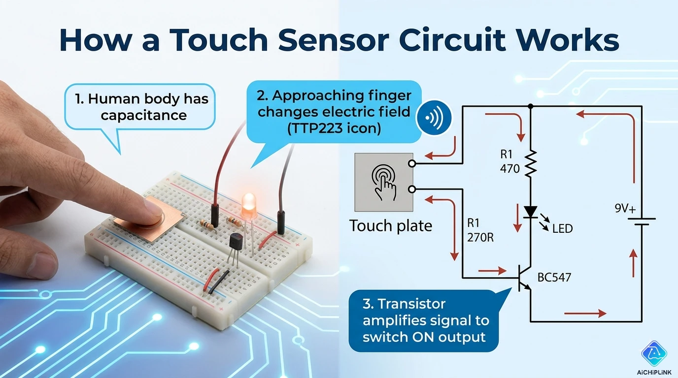
Simple Explanation: Touch sensors detect your finger by measuring changes in electrical properties when you touch a surface.
Two Main Types:
| Type | How It Works | Common Use |
|---|---|---|
| Capacitive | Detects change in capacitance | Smartphones, tablets |
| Resistive | Detects pressure connection | ATMs, industrial panels |
Bottom Line: Your finger changes the electrical field (capacitive) or completes a circuit (resistive), which the sensor detects.
Understanding Touch Sensing
What is a Touch Sensor?
ELI5 Explanation: Imagine a invisible bubble around a metal pad. When your finger gets close, it changes the bubble's shape. The sensor notices this change and knows you touched it.
Technical Definition: A touch sensor is an electronic component that detects physical touch or proximity by measuring changes in electrical properties (capacitance or resistance).
Capacitive Touch Sensors (Most Common)
How Capacitive Touch Works
The Physics (Simplified):
Step 1: Create an Electric Field
       Sensor Pad (Metal)
      ┌─────────────┐
      │             │ ← Connected to circuit
      └─────────────┘
           ║║║║║  ← Electric field
         (invisible)
Step 2: Your Finger Approaches
       👆 Finger
         │
    ┌────┴────┐
    │         │
    └─────────┘
     Sensor Pad

Your finger = capacitor plate
Creates capacitance between finger and sensor
Step 3: Measure Capacitance Change
Before Touch:  10 pF (picofarads)
During Touch:  15 pF ← Increased!
After Touch:   10 pF (returns to baseline)

Circuit detects: 50% increase = TOUCH DETECTED!
Capacitance Basics
What is Capacitance?
Water Tank Analogy:
Capacitor = Water tank
Charge = Amount of water
Capacitance = Size of tank

Bigger tank = More capacitance
Your finger = Adds extra tank volume
Formula:
C = ε × (A / d)

Where:
C = Capacitance (farads)
ε = Permittivity (material property)
A = Area of plates
d = Distance between plates

Your finger increases A → C increases
Simple Capacitive Touch Circuit
DIY Circuit (Using 555 Timer):
Components Needed:
- 555 Timer IC
- 1 MΩ resistor
- 100 nF capacitor
- LED
- Touch pad (aluminum foil works!)
- 9V battery

Circuit Diagram:

        +9V
         │
         ├──────────────┬─── Pin 8 (VCC)
         │              │
       [1MΩ]        ┌───┴───┐
         │          │  555  │
    Touch Pad ──────┤ 2   3 ├──[LED]── GND
    (Pin 2)         │       │
                    │ 1   7 ├──[100nF]── GND
                    └───┬───┘
                        │
                       GND

How it works:
1. Touch pad charges through 1MΩ resistor
2. Your finger adds capacitance
3. Charging takes longer
4. 555 timer detects timing change
5. LED turns ON when touched
Arduino Capacitive Touch
Using CapacitiveSensor Library:
Circuit:
Arduino Pin Setup:
Pin 4 (Send) ──[1MΩ resistor]── Pin 2 (Receive/Sensor)
                                     │
                               [Touch Pad]
                               (aluminum foil)

Pin 2 also connects to touch pad
Code:
#include <CapacitiveSensor.h>

// Pin 4 sends, Pin 2 receives
CapacitiveSensor cs_4_2 = CapacitiveSensor(4, 2);

void setup() {
  Serial.begin(9600);
  pinMode(13, OUTPUT); // Built-in LED
}

void loop() {
  long sensorValue = cs_4_2.capacitiveSensor(30);

  Serial.println(sensorValue);

  // Threshold: 1000 (adjust based on testing)
  if (sensorValue > 1000) {
    digitalWrite(13, HIGH); // Touch detected!
  } else {
    digitalWrite(13, LOW);
  }

  delay(10);
}
How It Works:
1. Pin 4 sends pulses to Pin 2 through 1MΩ resistor
2. Pin 2 measures how long to charge the capacitance
3. Your finger increases capacitance
4. Charging takes longer = higher sensorValue
5. If value > threshold → Touch detected
Typical Values:
No touch:     50-200
Light touch:  1000-3000
Firm touch:   5000-10000

Adjust threshold based on your setup!
Resistive Touch Sensors
How Resistive Touch Works
Two-Layer Structure:
Layer 1 (Top - Flexible)
   ┌─────────────┐
   │  ITO coating│ ← Transparent conductor
   │  (flexible) │
   └─────────────┘
        ↓ Press here
   ┌─────────────┐
   │  ITO coating│ ← Transparent conductor
   │  (rigid)    │
   └─────────────┘
Layer 2 (Bottom - Rigid)

ITO = Indium Tin Oxide (conductive & transparent)
Normal State (No Touch):
Layers separated → No connection → Open circuit
Voltage: 0V detected
Touched State:
Finger presses → Layers touch → Circuit completes
Voltage divider created → Position calculated
4-Wire Resistive Touch
How Position is Detected:
X-Axis Detection:
Apply voltage across left-right edges:
Left edge:  0V
Right edge: 5V

When touched:
Measure voltage at touch point
3V measured → 60% across (60% from left)
Y-Axis Detection:
Apply voltage across top-bottom edges:
Top edge:    5V
Bottom edge: 0V

Measure voltage at touch point
2V measured → 40% down from top
Result: Touch at (60%, 40%) position = pixel coordinates
Simple Resistive Touch Circuit
Pressure-Sensitive Button:
Components:
- 2 pieces of aluminum foil
- Foam spacer (with hole)
- Wires

Construction:
   Wire ────┤ Foil (top)
            │ Foam spacer
   Wire ────┤ Foil (bottom)

Circuit:
    +5V
     │
   [10kΩ]
     │
     ├───── Voltage measurement (Arduino A0)
     │
  [Touch Pad]
     │
    GND

When pressed:
- Foils touch
- Resistance drops
- Voltage drops
- Arduino detects change
Arduino Code:
void setup() {
  Serial.begin(9600);
  pinMode(13, OUTPUT);
}

void loop() {
  int sensorValue = analogRead(A0);
  Serial.println(sensorValue);

  // Threshold: <500 = pressed
  if (sensorValue < 500) {
    digitalWrite(13, HIGH);
  } else {
    digitalWrite(13, LOW);
  }

  delay(100);
}
Comparing Touch Technologies
Capacitive vs Resistive
| Feature | Capacitive | Resistive |
|---|---|---|
| Activation | Light touch/proximity | Pressure required |
| Accuracy | High | Moderate |
| Durability | Excellent (glass) | Moderate (plastic wears) |
| Multi-touch | Yes ✅ | No ❌ |
| Glove Use | No ❌ | Yes ✅ |
| Cost | Higher | Lower |
| Power | 3-5 mW | <1 mW |
| Transparency | 90%+ | 75-85% |
Use Case Recommendations
Choose Capacitive If:
- ✅ Smartphone/tablet interface
- ✅ Modern appliances (microwave, oven)
- ✅ High-end automotive displays
- ✅ Multi-touch gestures needed
- ✅ High durability required
Choose Resistive If:
- ✅ Industrial environment (dirty, wet)
- ✅ Glove operation required
- ✅ Stylus input needed
- ✅ Budget-constrained
- ✅ Simple single-touch interface
Advanced Touch Technologies
Projected Capacitive (PCAP)
What is PCAP? Multiple layers of electrodes in X-Y grid pattern.
Structure:
Glass Surface
┌─────────────┐
│ X electrodes│ (horizontal)
├─────────────┤
│ Y electrodes│ (vertical)
└─────────────┘

Detects touch at intersection:
X3, Y5 = Coordinate (3,5)
Advantages:
- Multi-touch (10+ fingers)
- Very accurate
- Works through glass (up to 6mm)
- Gesture recognition
Examples:
- iPhone/Android screens
- ATM machines (modern)
- Tablet displays
Self-Capacitance vs Mutual-Capacitance
Self-Capacitance:
Each sensor measures itself to ground
Pros: Simple, low cost
Cons: Ghost touches with multi-touch
Mutual-Capacitance:
Grid of X and Y electrodes
Measure capacitance between them
Pros: True multi-touch, no ghost touches
Cons: More complex, higher cost

Used in: All modern smartphones
Touch Sensor ICs
Popular Touch Controller Chips
1. TTP223 (Capacitive Touch):
Features:
- Single touch button
- Built-in regulator (2.0-5.5V)
- Toggle or momentary mode
- Very cheap ($0.20)

Pinout:
Pin 1: VCC (2-5.5V)
Pin 2: GND
Pin 3: Output (HIGH when touched)
Pin 4: Touch pad connection

No programming needed! Just connect and use.
Arduino Example:
int touchPin = 2;  // TTP223 output
int ledPin = 13;

void setup() {
  pinMode(touchPin, INPUT);
  pinMode(ledPin, OUTPUT);
}

void loop() {
  if (digitalRead(touchPin) == HIGH) {
    digitalWrite(ledPin, HIGH);
  } else {
    digitalWrite(ledPin, LOW);
  }
}
2. MPR121 (12-Channel Capacitive):
Features:
- 12 independent touch inputs
- I2C interface
- Programmable sensitivity
- Proximity detection

Use Case: Touch keyboard, musical instrument
Example:
#include <Adafruit_MPR121.h>

Adafruit_MPR121 cap = Adafruit_MPR121();

void setup() {
  Serial.begin(9600);
  cap.begin(0x5A);
}

void loop() {
  uint16_t touched = cap.touched();

  for (uint8_t i=0; i<12; i++) {
    if (touched & (1 << i)) {
      Serial.print("Pin ");
      Serial.print(i);
      Serial.println(" touched!");
    }
  }
  delay(100);
}
3. AT42QT1070 (7-Channel):
Features:
- 7 touch keys
- I2C interface
- Auto-calibration
- Low power (1.8-5V)

Use: Custom control panels
DIY Touch Projects
Project 1: Capacitive Touch Lamp
Components:
- Arduino Nano
- TTP223 touch module
- MOSFET (IRLZ44N)
- 12V LED strip
- 12V power supply
Circuit:
Touch Sensor:
TTP223 VCC ── 5V (Arduino)
TTP223 GND ── GND
TTP223 OUT ── Pin 2 (Arduino)

LED Control:
Pin 3 (PWM) ── Gate (MOSFET)
Source ────── GND
Drain ─────── LED Strip (-)
LED Strip (+) ─ +12V

Power:
12V supply (+) ── LED strip, Arduino VIN
12V supply (-) ── GND (common)
Code:
int touchPin = 2;
int ledPin = 3;
int brightness = 0;
bool ledState = false;

void setup() {
  pinMode(touchPin, INPUT);
  pinMode(ledPin, OUTPUT);
}

void loop() {
  if (digitalRead(touchPin) == HIGH) {
    delay(50); // Debounce
    if (digitalRead(touchPin) == HIGH) {
      ledState = !ledState;

      if (ledState) {
        // Fade in
        for (brightness = 0; brightness <= 255; brightness += 5) {
          analogWrite(ledPin, brightness);
          delay(20);
        }
      } else {
        // Fade out
        for (brightness = 255; brightness >= 0; brightness -= 5) {
          analogWrite(ledPin, brightness);
          delay(20);
        }
      }

      while (digitalRead(touchPin) == HIGH); // Wait for release
    }
  }
}
Project 2: Touch Piano (8 Keys)
Components:
- Arduino Uno
- 8× aluminum foil pads
- 8× 1MΩ resistors
- Buzzer or speaker
- Jumper wires
Circuit:
For each key (repeat 8 times):
Pin X (send) ──[1MΩ]── Pin Y (receive) ── Touch Pad
                                             │
                                        [Foil pad]

Buzzer:
Pin 8 ─── + (Buzzer)
GND ───── - (Buzzer)

Keys: Use pins 2-9 for 8 notes
Code:
#include <CapacitiveSensor.h>

// Create 8 sensors
CapacitiveSensor key[8] = {
  CapacitiveSensor(10, 2),  // C
  CapacitiveSensor(10, 3),  // D
  CapacitiveSensor(10, 4),  // E
  CapacitiveSensor(10, 5),  // F
  CapacitiveSensor(10, 6),  // G
  CapacitiveSensor(10, 7),  // A
  CapacitiveSensor(10, 8),  // B
  CapacitiveSensor(10, 9)   // C (high)
};

int notes[] = {262, 294, 330, 349, 392, 440, 494, 523}; // C major scale
int buzzerPin = 11;

void setup() {
  pinMode(buzzerPin, OUTPUT);
}

void loop() {
  for (int i = 0; i < 8; i++) {
    long value = key[i].capacitiveSensor(30);

    if (value > 1000) {  // Threshold
      tone(buzzerPin, notes[i]);
      delay(100);
      noTone(buzzerPin);
    }
  }
}
Project 3: Touchless Gesture Sensor
Using Proximity Detection:
Circuit:
Large copper plate (10×10 cm) as antenna
Connect to Arduino capacitive touch

Detects hand approach from 5-30 cm away!
Applications:
- Automatic faucets
- Hands-free door opener
- Presence detection
- COVID-safe interfaces
Troubleshooting Touch Sensors
Problem 1: Capacitive Touch Too Sensitive
Symptoms:
- Triggers without touching
- Detects from far away
- Random false triggers
Solutions:
1. Reduce Sensing Resistor
Change: 10MΩ → 1MΩ
Effect: Less sensitive, shorter range
2. Add Ground Plane
Place copper foil under sensor
Connect to GND
Effect: Shields from interference
3. Lower Threshold in Code
Before: if (value > 1000)
After:  if (value > 3000)  // Higher threshold
Problem 2: Not Sensitive Enough
Symptoms:
- Requires firm pressure
- Doesn't detect light touch
- Inconsistent detection
Solutions:
1. Increase Sensing Resistor
Change: 1MΩ → 10MΩ
Effect: More sensitive
2. Larger Touch Pad
Increase pad area: 1cm² → 4cm²
More capacitance = better detection
3. Multiple Samples
// Average 10 readings
long total = 0;
for (int i = 0; i < 10; i++) {
  total += cs.capacitiveSensor(30);
}
long average = total / 10;
Problem 3: Erratic Behavior
Symptoms:
- Random triggers
- Unstable readings
- Works sometimes
Solutions:
1. Add Decoupling Capacitor
0.1µF ceramic cap between VCC and GND
Place close to IC/Arduino
2. Shield Sensor Traces
Run ground wire parallel to sensor wire
Reduces electromagnetic interference (EMI)
3. Auto-Calibration
long baseline = 0;

void setup() {
  // Measure baseline (no touch)
  for (int i = 0; i < 100; i++) {
    baseline += cs.capacitiveSensor(30);
  }
  baseline /= 100;
}

void loop() {
  long value = cs.capacitiveSensor(30);
  long delta = value - baseline;  // Use relative change

  if (delta > 500) {  // Touch detected
    // Action
  }
}
Best Practices
Design Guidelines
1. Touch Pad Design:
Optimal Pad Size:
- Buttons: 10-15 mm diameter
- Sliders: 5 mm wide, 50+ mm long
- Wheels: 15-20 mm segments

Material: Copper (PCB), aluminum foil, conductive fabric
2. Grounding:
Essential: Ground plane under sensor
Size: Larger than sensor pad
Connection: Arduino GND

Improves: Stability, noise immunity
3. Calibration:
Always calibrate at startup:
1. Take 100 baseline readings
2. Average them
3. Use delta from baseline for detection

Prevents: Environmental drift
Safety Considerations
For Mains-Powered Devices:
⚠️ DANGER: Never connect touch sensor directly to mains voltage!
Proper Isolation:
Mains (120V/230V)
    ↓
[Isolated Power Supply] (UL listed)
    ↓
Low voltage (5V/12V DC) ← Safe for touch sensors
    ↓
Touch sensor circuit
Optoisolator for Control:
Touch Sensor → Arduino → Optoisolator → Relay → Mains Device

Optoisolator provides electrical isolation
Safety first!
Future of Touch Technology
Emerging Technologies (2026)
1. Force Touch / 3D Touch:
Detects:
- Light tap
- Firm press
- Hard press (different actions)

Example: iPhone (pressure-sensitive screen)
2. Ultrasonic Touch:
How: Ultrasonic waves through glass
Advantage: Works underwater, with gloves
Use: Rugged phones, underwater cameras
3. In-Display Fingerprint:
Technology: Optical or ultrasonic
Integration: Touch + biometric in one
Adoption: 80% of flagship phones (2026)
4. Mid-Air Gesture:
Technology: Ultrasonic haptic feedback
Example: Feel "buttons" in air without screen
Status: Early adoption (BMW, concept cars)
Summary & Key Takeaways
Understanding Touch Sensors:
✅ Capacitive Touch:
- Detects change in electric field
- No pressure needed
- Used in smartphones
- Multi-touch capable
✅ Resistive Touch:
- Detects physical pressure
- Layers must contact
- Works with gloves
- Lower cost
✅ DIY Touch Circuits:
- Arduino + CapacitiveSensor library
- Simple as 2 pins + 1MΩ resistor
- Aluminum foil works as touch pad
✅ Touch Controller ICs:
- TTP223: Single button ($0.20)
- MPR121: 12 channels
- Easy to integrate
✅ Best Practices:
- Use ground plane
- Auto-calibration essential
- Proper shielding for stability
Conclusion
Touch sensors have revolutionized human-computer interaction, replacing mechanical buttons with elegant, reliable interfaces. Understanding the basic principles - whether capacitive detection of electric field changes or resistive detection of pressure - enables you to design and troubleshoot touch-enabled projects.
For hobbyists and makers, capacitive touch sensors offer an accessible entry point with Arduino libraries and cheap components like TTP223 or MPR121 ICs. Professional applications leverage advanced PCAP technology for multi-touch displays in smartphones and tablets.
The future of touch continues to evolve with force-sensitive displays, in-display fingerprint sensors, and even mid-air haptic feedback bringing science fiction interfaces to reality.
For more electronics tutorials, Arduino projects, and sensor guides, visit AiChipLink.com.

Written by Jack Elliott from AIChipLink.
AIChipLink, one of the fastest-growing global independent electronic components distributors in the world, offers millions of products from thousands of manufacturers, and many of our in-stock parts is available to ship same day.
We mainly source and distribute integrated circuit (IC) products of brands such as Broadcom, Microchip, Texas Instruments, Infineon, NXP, Analog Devices, Qualcomm, Intel, etc., which are widely used in communication & network, telecom, industrial control, new energy and automotive electronics.
Empowered by AI, Linked to the Future. Get started on AIChipLink and submit your RFQ online today!
Frequently Asked Questions
How does a capacitive touch sensor detect your finger?
A capacitive touch sensor detects changes in Capacitance when your finger approaches or touches the sensor. Your body acts like a conductive plate, increasing capacitance, which the circuit measures to determine a touch event.
What is the difference between capacitive and resistive touch sensors?
Capacitive sensors detect changes in an electric field and require only light touch, while resistive sensors rely on physical pressure to connect two conductive layers. Capacitive is more modern and supports multi-touch, whereas resistive works better with gloves and harsh environments.
Why is a resistor used in Arduino capacitive touch circuits?
The resistor (often 1MΩ–10MΩ) controls how fast the sensor charges and discharges. A higher resistance increases sensitivity by making capacitance changes more noticeable, allowing the system to detect even slight touches.
Why do capacitive touch sensors sometimes give false triggers?
False triggers are usually caused by electromagnetic interference (EMI), poor grounding, or excessive sensitivity. Adding a ground plane, adjusting thresholds, or improving shielding can stabilize the readings.
Can touch sensors work without direct contact?
Yes. Capacitive sensors can detect proximity because they respond to changes in the electric field, allowing them to sense a finger even a few centimeters away—commonly used in gesture control and touchless interfaces.