A Complete Guide to the 5V Single Channel Relay Module
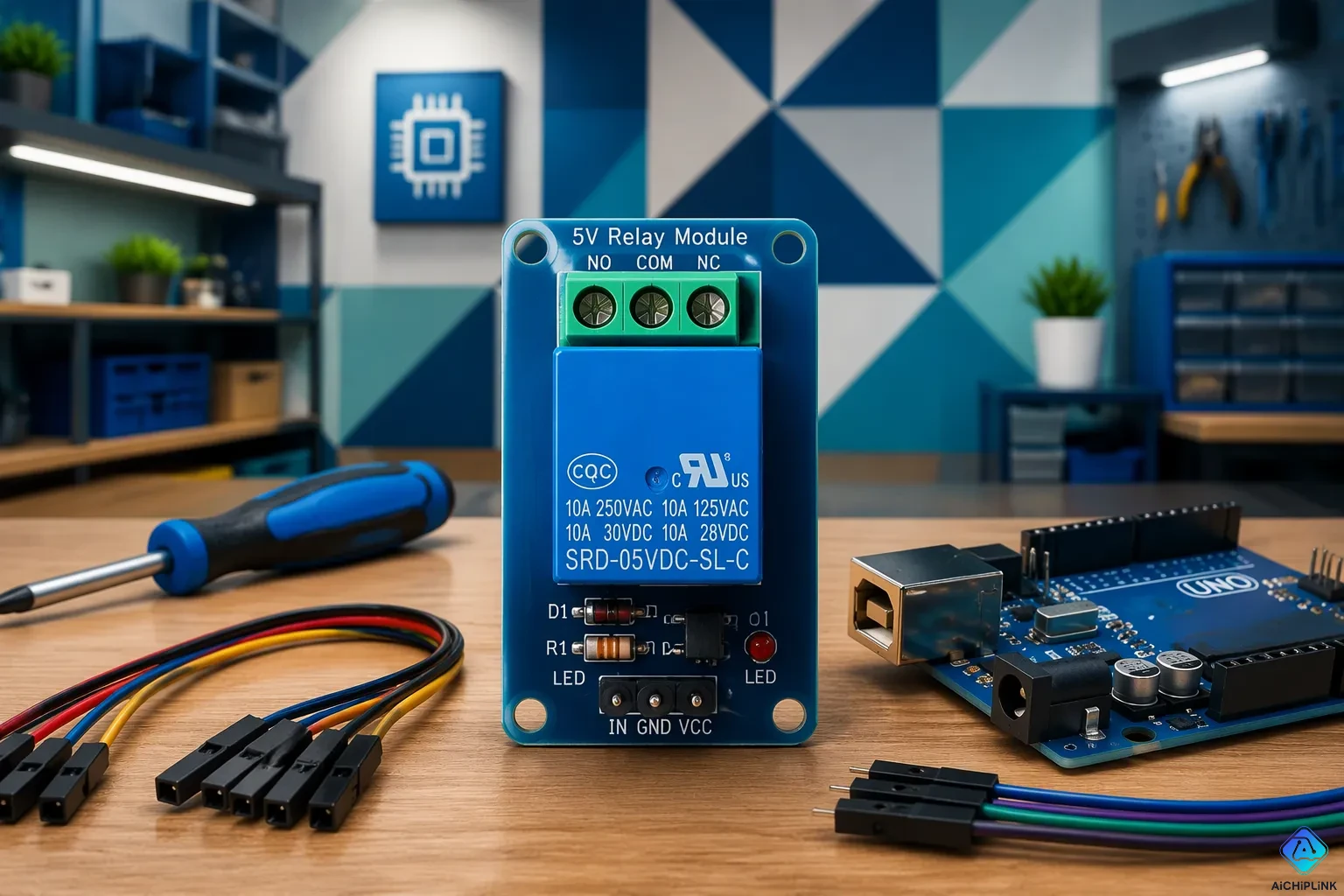
A 5V single channel relay module is a small board that lets a weak 5V control signal switch a higher-power device. It fixes a common problem: microcontrollers like Arduino output only about 5V at low current. That is not enough to drive lights, fans, motors, or solenoids directly. Wikipedia's Arduino Uno entry notes that each pin handles 20 mA as the recommended operating condition. It also says that going over 40 mA risks permanent damage:
A maximum of 40mA must not be exceeded on any I/O pin to avoid permanent damage to the microcontroller.
This guide walks you through the working principle, pin configuration, wiring steps, and common uses of the 5v relay module. That way, you can connect high-power devices with confidence.
Key Takeaways
-
A 5V single channel relay module lets a weak microcontroller signal control high-power devices safely.
-
Connect VCC to 5V, GND to ground, and IN to a digital pin to control the relay.
-
Test the trigger mode first: send a LOW or HIGH signal to see if the relay activates.
-
Wire your load through COM and NO for devices that should stay off by default.
-
Always power down before wiring and keep mains voltage away from the low-voltage pins.
What Is a 5V Single Channel Relay Module
Relay Module Basics
A relay module is a board that holds one or more relays, plus the extra parts that keep things separate and safe. The single channel version has just one relay. That relay works like a switch you control with electricity. A small control signal turns a much bigger load circuit on or off.
The 5V rating is about the coil side, not the load side. You give the board 5 volts, and the relay coil pulls the current it needs. The control side stays at a low voltage. The load side can switch much higher voltages and currents. Cestore publishes typical figures for a 1-channel 5V 10A board.
| Specification | Value |
|---|---|
| Supply voltage | 3.75V to 6V |
| Quiescent current | 2mA |
| Current when the relay is active | ~70mA |
| Relay control voltage | 5.0V directly via microcontroller |
Module Board vs. Bare Relay
A bare 5v relay is only the electromechanical switch. The 5v relay module adds the parts that make it safe and simple to use. Viox lists screw terminals for COM, NO, and NC, flyback diodes that soak up coil voltage spikes, optocouplers for optical isolation, LED indicators, and transistor drivers that boost the weak control signal.
These extras matter for beginners. The driver transistor lets a weak pin signal run the coil. The flyback diode shields your microcontroller from voltage spikes. The screw terminals hold thicker wires for high-power devices. Qianji Relay notes that opto-isolated boards make a full electrical air gap between the microcontroller and the driver circuit. An internal 5v single channel relay module diagram usually shows these blocks in order: input pins, optocoupler, transistor, coil, and relay contacts.
The board also works with microcontrollers like Arduino, AVR, PIC, ARM, Raspberry Pi, and MSP430. That makes the single channel 5v relay module a popular first pick for prototyping.
How a 5V Relay Module Works
Coil and Contacts
The working of 5v relay module starts with a simple magnetic switch. Onpowbutton describes the sequence in clear steps:
-
A spring holds the moving assembly in its normal position.
-
Current through the relay coil produces a magnetic field.
-
The magnetic circuit attracts an armature and overcomes the restoring force.
-
The armature moves the contact mechanism.
-
Removing coil power lets the spring return the contacts to their normal state.
The internal coil may use only small amounts of power, according to workforce.libretexts.org. The relay contacts it moves can carry hundreds of times that power to a load. A minimum pull-in current must flow before the armature moves. Once pulled in, less current keeps it there. The coil current must drop below the drop-out current before the contacts return. That gap between pull-in and drop-out works like a Schmitt trigger gate. This hysteresis stops the relay from chattering when the control signal sits near the threshold.
Most single channel boards use an SPDT arrangement. Three load terminals serve this switch: NC (normally closed), C (common), and NO (normally open). The C terminal connects to one side of your load. You pick NO for a load that stays off until the relay activates. You pick NC for a load that stays on until activation. The moving contact inside the relay decides which path carries current.
Driver Circuit and Isolation
A microcontroller pin cannot drive the coil alone. Eleccircuit.com notes that a relay coil needs about 100 mA, while a normal digital output supplies about 2 mA. A driver transistor bridges that gap. It acts as a switch that lets a small base current control a much larger collector current. Industrialmonitordirect.com explains that a single-transistor stage turns a 5 V, roughly 1 mA logic output into a hard 5 V drive. That drive energizes the opto-isolated inputs on common 5 V relay modules.
| Aspect | Detail |
|---|---|
| Function | Single-transistor stage that turns a weak logic output into a hard 5 V drive |
| Typical design | NPN BJT (2N3904) common-emitter switch, with an N-channel MOSFET (2N7000) variant |
| LED operating range | Between 2.5 mA minimum trigger current and 50 mA absolute maximum for the EL817 family |
An optocoupler adds optical isolation. An infrared LED inside the coupler flashes across a gap to a phototransistor. The low-power control signals never touch the load side electrically. This protects your board from voltage spikes on the load circuit. The 5v signal stays on the safe side of the barrier. The relay module keeps the two circuits apart even when the load side switches mains voltage.
Many boards use a low-level trigger. A LOW signal on the IN pin activates the relay. A HIGH signal releases it. Check your board's behavior before you wire a real load. A single channel relay module circuit diagram usually marks the trigger type near the input header. The relay module circuit diagram also shows the flyback diode across the coil. That diode absorbs the voltage spike when the coil de-energizes. A quick test with a multimeter confirms the trigger mode before you connect anything expensive.
5V Relay Module Pin Configuration
Input Pins: VCC, GND, IN
The input side of a 5v relay module has three pins, and Components101 lists them in order: Relay Trigger, Ground, and VCC. You connect VCC to a 5 volts supply, GND to the ground rail, and IN to any digital pin on your microcontroller. The VCC pin feeds the relay coil, so it needs a steady supply. A weak supply makes the relay behave unpredictably.
The IN pin carries your control signal. Elprocus explains that this signal pin works in two modes: active low or active high. In active low mode, the relay activates when you send a low signal. In active high mode, a high signal triggers it. Many boards ship with active high behavior, which energizes the coil and pulls the common terminal toward the normally open contact. Always confirm the mode on your own board before wiring a load.
Output Terminals: COM, NO, NC
The output side uses three screw terminals. COM is the common terminal, and you connect it to the supply side of your load circuit. NO stands for normally open, and it connects to a load that stays off until the coil energizes. NC stands for normally closed, and it keeps a load running until activation. JLCPCB puts the choice plainly: wire a heater, pump, or lamp to NO so it stays off after a power loss, and wire a ventilation fan to NC so it keeps running unless your controller turns it off.
Your choice between the no or nc terminals depends on what should happen when the controller resets or loses power. A relay pin diagram for an SPDT board shows all three contacts, and a single channel unit uses exactly this arrangement. Terminal labels vary slightly between manufacturers, so read the silkscreen before you tighten any screw. The printed 5v relay pin configuration on the board is your final reference, not the product photo.
Wiring a 5V Relay Module to a Microcontroller
Connection Steps
You need only three signal wires between an Arduino Uno and the relay module, according to Medium's beginner guide. The table below shows each connection.
| Arduino Uno | Relay Module |
|---|---|
| 5V | VCC |
| GND | GND |
| Digital Pin 7 | IN |
Follow these steps in order:
-
Connect the Arduino 5V pin to VCC on the board. This pin powers the coil.
-
Connect the Arduino GND pin to GND on the module.
-
Wire a digital pin, such as Pin 7, to the IN pin.
-
Wire your load through COM and NO. The device stays off until the relay receives a control signal.
Random Nerd Tutorials confirms this layout: GND goes to ground, VCC goes to 5V, and the IN pin connects to a digital pin. A single channel board has just one IN pin, so the wiring stays simple. The 5v relay module is compatible with microcontrollers from many families, which makes this layout a common starting point.
Now connect the load side. Run the positive supply wire to COM. Run the load's other wire to NO for a device that should stay off by default. Choose NC instead if the device should run until activation. This single-channel relay module circuit keeps the control side and the load side apart, so your low-power microcontrollers never touch the high-power devices directly.
Trigger Mode Check
Test the trigger mode before you connect a real load. Power the board and watch the status LED. Send a LOW signal from your code. If the LED lights and the relay clicks, the board is active-low. If nothing happens, send a HIGH signal and listen again. Many boards ship active-high, so confirm the behavior on your own unit. A quick bench test with a small lamp protects your project from a wrong assumption.
Safety deserves equal care. Omron's safety precautions state that you must turn off the power and confirm there is no residual voltage before wiring or replacing a relay. The same page warns you never to touch the terminal section while power is supplied, because electric shock may occur. Keep mains wiring physically away from the low-voltage header. Use insulating coverings on exposed conductors. Tighten every screw terminal firmly, since Omron notes that loose screws may cause abnormal heat and burning during energization. Power down before every change, and treat the 5v relay contacts with respect whenever a mains load is attached.
Applications and Troubleshooting
Common Uses
You will see the relay module in many everyday projects. Vocal Media lists three main areas where it works well:
-
Home automation — control household appliances like lights, fans, or air conditioners from a distance.
-
Robotics — run motors or other high-power parts in robots.
-
Industrial automation — handle process control and automation jobs in industrial settings.
Beyond those groups, the same board switches lamps, solenoids, solenoid valves, heaters, and AC devices. The applications of 5v relay module designs stay wide because the board works with microcontrollers from Arduino, Raspberry Pi, and PIC families. Simple wiring, isolation between control and load, low cost, and easy prototyping explain why people like it. The 5v relay handles high-power devices and high-voltage devices on the load side while your logic pin stays safe. Check your board's current capacity against the load before you commit.
Fixing Common Issues
Start with the simplest fault: the relay clicks but the load stays off. Your COM and NO wiring is the usual cause. Confirm the supply wire sits on COM and the load wire sits on NO. Swap to NC only when the device should run by default.
A relay that never clicks points to the control side. Allpcb suggests a practical order. Inspect the board for burn marks, loose terminals, or corrosion. Test the relay coil with a multimeter set to ohms; a typical coil resistance might range from 50 to 500 ohms, and an infinite reading means a burnt coil. Verify the control signal matches the rated voltage. Confirm the load does not exceed the relay rating; Allpcb notes that a load drawing 8A on a 5A relay will cause overheating and failure.
Erratic behavior usually means a weak supply. The 5v relay coil draws a current surge at activation, so a thin USB cable or shared rail can cause dropouts. Power the single channel board from a steady 5V source. A single channel relay module rewards careful wiring with years of reliable switching.
The 5v single channel relay module earns its place in your parts box. It bridges low-power control electronics and high-power loads with simple wiring, solid isolation, and a low price. You get one reliable switch between a weak logic pin and a real device.
This relay module fits hobby builds, home automation, and quick prototypes alike. The single channel layout keeps your first project manageable. Try the 5v relay module with a small lamp or fan this weekend. Test the trigger mode first, then wire the load through COM and NO. Treat any mains connection with care, and power down before you touch a terminal. Your 5v relay will reward that caution for years.

Written by Jack Elliott from AIChipLink.
AIChipLink, one of the fastest-growing global independent electronic components distributors in the world, offers millions of products from thousands of manufacturers, and many of our in-stock parts is available to ship same day.
We mainly source and distribute integrated circuit (IC) products of brands such as Broadcom, Microchip, Texas Instruments, Infineon, NXP, Analog Devices, Qualcomm, Intel, etc., which are widely used in communication & network, telecom, industrial control, new energy and automotive electronics.
Empowered by AI, Linked to the Future. Get started on AIChipLink and submit your RFQ online today!
Frequently Asked Questions
Can I power the 5v relay module from the Arduino 5V pin?
Yes, for a single channel board. The coil draws roughly 70 mA when active, and the Arduino 5V pin can supply that. Avoid powering several boards from the same pin. A separate 5V supply gives you steadier switching.
Why does my relay click but nothing turns on?
Your load wiring is the likely culprit. Check that the supply wire sits on COM and the load wire sits on NO. Move the load wire to NC only when the device should run by default. Tighten both screws before you test again.
How do I know if my board is active-low or active-high?
Run a quick bench test. Send a LOW signal and watch the status LED. A click means the board is active-low. No reaction means you should try a HIGH signal. Confirm the trigger mode before you connect any real load to the 5v relay.
Can a 5v relay switch mains voltage?
Many boards rate their contacts for mains-level loads, but you must check your own unit's rating first. Keep mains wiring away from the low-voltage header. Power down before every change. Treat every terminal as live until you verify otherwise.
Do I need a separate power supply for the relay module?
Usually not for one board. A single channel unit runs fine from the Arduino 5V pin. Erratic clicking or dropouts point to a weak supply. In that case, feed the 5v relay module from its own 5V source and share only ground with the microcontroller.