How to Calculate Flyback Diode Values for 5V, 12V, and 24V Relays
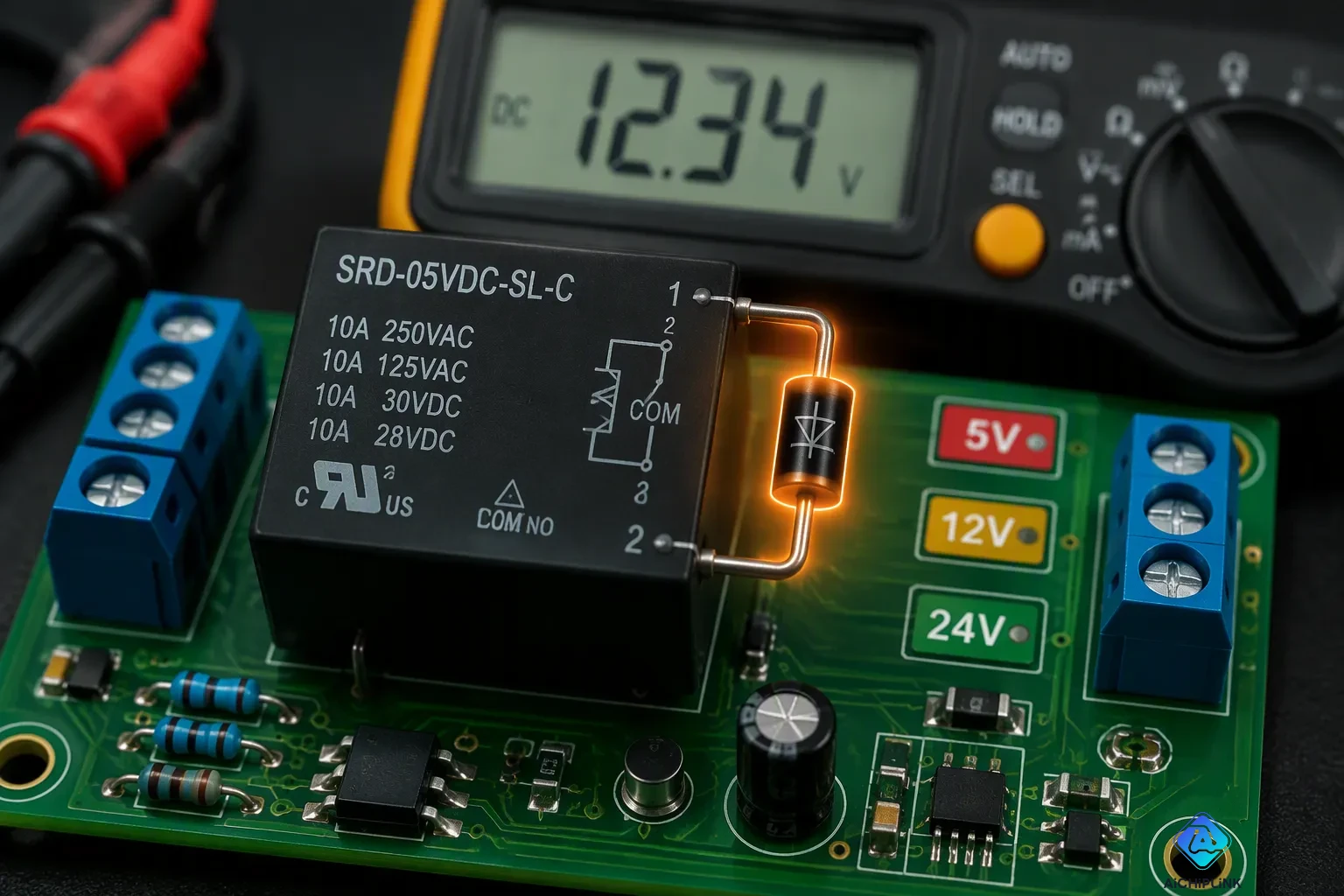
To pick the right flyback diode, start with proper Flyback Diode Relay Selection. First, find the relay coil current using the formula I = V divided by R. Here, V is the relay supply voltage, and R is the coil resistance. Next, choose a diode with a current rating equal to or higher than that coil current. The reverse voltage rating must be at least 1.5 to 2 times the supply voltage. For example, a 5V relay often has a coil current around 70 mA. This method gives a simple and reliable approach to Flyback Diode Relay Selection. You can apply it to 5V, 12V, and 24V relay versions. The guarding diode always protects the driving transistor from the voltage spike when the coil turns off—this spike is known as the flyback effect.
Key Takeaways
-
Find the relay coil current with I = V / R. Here, V is the supply voltage, and R is the coil resistance.
-
Pick a flyback diode. Its current rating must be equal to or higher than the coil current. Its reverse voltage rating must be 1.5 to 2 times the supply voltage.
-
For 5V and 12V relays, the 1N4148 diode is a good choice; for 24V relays, pick the 1N4002 diode instead.
-
Put the flyback diode right across the relay coil's terminals, with the cathode on the positive side and the anode on the negative side.
-
Always check the relay datasheet for the exact coil resistance. This helps you pick the right diode and keep the relay safe.
Flyback Diode Role in Relay Circuits
Necessity of Flyback Diodes
When you turn off a relay, the coil has stored energy in its magnetic field. That energy needs a place to go. The sudden stop of current makes a voltage spike, called inductive kickback. The formula for this spike is voltage equals inductance times the change in current over time. A small inductance can create a surprisingly large voltage when the current drops fast.
Think about a servo motor with 10 mH of inductance. If it turns off in 1 microsecond, it can make a 100V spike on a 12V circuit. That spike can harm your driving transistor or microcontroller. Without protection, you may get random failures.
A servo motor with 10 mH of inductance that turns off in 1 microsecond can make a 100V spike on a 12V circuit.
You may see these problems in your own projects:
-
The microcontroller resets or times out when motors start or stop
-
Sensor readings become wrong when motors are running
-
Input modules in PLCs fail without clear reason
-
Servo motors act erratically
All these signs point to one cause: missing flyback protection. A flyback diode circuit stops these problems by giving the coil a safe path for its stored energy.
Circuit Protection Mechanism
The flyback diode connects across the relay coil terminals. You put the cathode on the positive supply side and the anode on the negative side. During normal use, the diode blocks current because it is reverse-biased. When you turn off the coil, the voltage flips polarity. The diode becomes forward-biased and starts to conduct.
This action holds the voltage at a safe level. The coil current flows through the diode and slowly drops. The driving transistor never sees the full spike. The flyback diode takes in the energy and gives it off as heat.
Flyback diodes are very good at protecting electronic circuits from voltage surges caused by inductive loads like relays, solenoids, and DC motors. Adding them to circuit designs can make these systems last longer and work better. Every relay you drive with a transistor needs this protection. The diode costs only a few cents, but it saves your expensive parts from being destroyed.
Calculating Flyback Diode Ratings for Relays
Determining Relay Coil Current
First, find the coil current to pick a flyback diode. The formula is easy: coil current = relay voltage ÷ coil resistance. Write it as I = V / R. The relay voltage comes from your power supply. The coil resistance is in the relay datasheet. You can measure it with a multimeter too.
Relays have different coil resistances. A 12V car relay often has a coil resistance from 50 to 200 ohms. A 24V system relay is usually between 200 and 600 ohms. These ranges are a starting point. Always check the exact value for your relay.
Let's try an example. Imagine you have a 12V relay with a coil resistance of 350 ohms. Divide 12 by 350. You get about 0.034 amps, which is 34 milliamps. That number shows the coil current during normal use. This current is your baseline for picking a diode.
A 5V relay usually has a coil current between 70 and 100 milliamps. For a 24V relay, some industrial units have a coil resistance as low as 10 ohms. That low resistance gives a much higher coil current. Calculate carefully for each relay.
The coil current is important because it sets the minimum current rating for the flyback diode. The diode must handle the same current as the coil. If you pick a diode with a lower rating, it will get too hot and break.
Selecting Diode Current and Voltage Ratings
After you know the coil current, use two selection rules. First, the diode's current rating must be equal to or more than the coil current. Second, the reverse voltage rating must be at least 1.5 to 2 times the supply voltage. These rules keep the circuit safe.
The reverse voltage rule guards against the flyback spike. When the coil turns off, the voltage can go much higher than the supply. A diode rated only at the supply voltage might fail. The 1.5 to 2 times margin gives you a safety buffer.
Common diodes work well for most relay circuits. The 1N4148 can handle 100 volts and 200 milliamps. This diode is good for 5V and 12V relays with normal coil currents. The 1N4001 handles 50 volts and 1 amp. It also works for 12V relays. The 1N4002 handles 100 volts and 1 amp. This one fits 24V relays because its 100-volt rating meets the derating rule.
Let's check the numbers for a 24V relay. The supply voltage is 24 volts. Multiply by 2 to get 48 volts. The 1N4002 with its 100-volt rating easily meets that need. The 1N4001 with only 50 volts is too close to the limit. So pick the 1N4002.
Your flyback diode relay selection process is always the same. Calculate the coil current. Apply the voltage derating rule. Match the diode to both needs. This method works for any relay voltage.
The table below summarizes typical coil resistance ranges for common relay voltages.
| Relay Voltage | Typical Coil Resistance Range |
|---|---|
| 12V (automotive) | 50 – 200 ohms |
| 24V (systems) | 200 – 600 ohms |
Remember that these ranges vary by manufacturer. Always check the coil resistance from your relay datasheet before choosing the flyback diode. A wrong guess can cause early diode failure and unprotected circuits.
Flyback Diode Relay Selection Examples
5V and 12V Relay Examples
For a 5V relay with a coil current of 70 mA, you need a diode that can handle this current. The flyback diode must also block the reverse voltage spike. A 1N4148 diode works well for this case. It has a 200 mA current rating and a 100 V reverse voltage rating. This gives you plenty of margin for the 70 mA coil current. The 1N4007 diode also works for slower coils. It can handle 1 A of current and 1000 V of reverse voltage. Both options protect your circuit from the flyback effect. The 1N4007 is a good choice if you want extra headroom for future projects. You can use either diode for a 5V relay with confidence.
Flyback diode is mandatory. A relay coil is inductive. When the transistor switches off, the collapsing magnetic field generates a reverse EMF spike of tens to hundreds of volts. The 1N4148 (or 1N4007 for slower coils) clamps this spike to about 0.7 V, protecting the transistor and the Arduino pin.
For a 12V relay with a coil current of 34 mA, the selection process is similar. You calculate the current first. Then you match it to a diode. The 1N4148 remains a good choice. It has a 200 mA current rating, which covers the 34 mA coil current with room to spare. Its 100 V reverse voltage rating also meets the derating rule. You need at least 24 V of reverse voltage for a 12V supply. The 1N4148 gives you 100 V, so it works perfectly. This diode is the most common option for low-power relays. It works for both 5V and 12V circuits.
| Diode | Current Rating | Reverse Voltage | Recovery Time | Suitability for 12V, 34mA Coil |
|---|---|---|---|---|
| 1N4148 | 200 mA | 100 V | 4 ns | Recommended – covers 34 mA with margin |
| 1N5819 (Schottky) | 1 A | 40 V | Fast | Overkill but works; lower forward drop |
| UF4007 | 1 A | 1000 V | Fast | Overkill; better for high-voltage apps |
The 1N4148 meets all requirements for your 12V relay. This is the most cost-effective flyback diode for this application. The 1N5819 Schottky diode also works. It has a lower forward voltage drop, which helps in hot switching situations. But the 1N4007 or 1N5819 may be overkill for a simple relay circuit. Stick with the 1N4148 for most cases. You can find this diode in any electronics store. It costs only a few cents per piece.
24V Relay Example
For a 24V relay, you need a different diode. The derating rule requires a reverse voltage of at least 48 V. Multiply 24 V by 2 to get 48 V. The 1N4002 diode has a 100 V reverse voltage rating. It meets the rule easily. The 1N4001 only has 50 V, which is too close to the limit. Do not use that part for a 24V relay. The 1N4002 gives you a safety margin of more than 2 times the supply voltage. This margin ensures reliable operation over many switching cycles.
The current for this supply voltage is typically around 34 mA. This is similar to the 12V example. The 1N4002 handles 1 A of current, so it covers the 34 mA coil current with plenty of margin. This diode is a standard choice for your flyback diode relay selection process. It costs very little but provides reliable protection.
Your flyback diode relay selection always follows the same steps. Find the coil current. Apply the voltage derating rule. Pick a diode that meets both requirements. For 5V and 12V relays, use the 1N4148 or 1N4007. For 24V relays, use the 1N4002. The correct diode prevents damage to your circuit. These choices protect your relay coil and the driving transistor from damage. Always check the relay datasheet for exact coil resistance values. This small step saves you from costly repairs later.
Additional Flyback Diode Selection Tips
Switching Speed and Diode Type
How fast your circuit switches changes which flyback diode you should pick. Standard diodes like the 1N4002 work fine for slow switching. They take longer to recover. This delay creates extra heat and noise when you switch at high frequencies. For PWM control or fast switching, choose a Schottky or ultra-fast diode instead. These parts have a low reverse recovery charge. They reduce ringing and cut switching losses.
You should also add a safety margin to your voltage math. Add 30% to the computed reverse voltage to cover parasitic ringing and spikes. For example, a 52V spike becomes 67.6V with this margin. Then make sure the flyback diode's voltage rating sits at least 80% above that adjusted voltage. Divide 67.6V by 0.8 to get 84.5V. A standard 100V diode meets this need. Apply the same logic to current. Pick a flyback diode with a current rating at least 80% higher than the computed current. For a 10A coil, choose a diode rated above 12.5A.
Think about other diode types for special cases. Metal oxide varistors handle AC spikes. Transient-voltage-suppression diodes act fast and work bidirectionally. Zener diodes trigger on reverse voltage. Schottky diodes offer a low forward voltage drop but tolerate less reverse voltage. Your choice of flyback diode also depends on the relay's duty cycle.
Placement and Wiring Tips
Where you place your flyback protection diode matters as much as its ratings. Connect the diode in parallel with the relay coil. Put the cathode on the positive supply side and the anode on the negative side. This setup keeps the diode reverse-biased during normal operation. When the switch opens, the coil's polarity reverses. The diode becomes forward-biased and clamps the voltage spike.
Place the diode directly across the relay coil terminals. Solder it to the coil pins if possible. This position creates the shortest path for the freewheeling current. It also shrinks the loop area that could act as an EMI antenna. A smaller loop radiates less noise. Your flyback diode circuit works better with tight wiring.
For remote loads, add a second diode at the load terminals. Long wiring adds stray inductance. This inductance can cause voltage overshoot. A second diode at the load fixes that problem. You can also use a Zener clamp in series with the diode. This setup speeds up current decay and shortens the time the loop radiates.
Every relay you drive with a transistor needs this protection. The flyback effect can destroy your switching component without warning. A few cents of diode saves you from costly replacements.
You now know the three steps for flyback diode selection. First, calculate the relay coil current with I = V / R. Second, apply the 1.5 to 2 times derating rule for reverse voltage. Third, pick a flyback diode with matching ratings. The 1N4148 works for 5V and 12V relays. The 1N4002 suits 24V relays. Always check the coil resistance from your datasheet. This flyback protection prevents damage.
| Voltage | Typical Coil Current | Suggested Diode |
|---|---|---|
| 5V | 70 mA | 1N4148 |
| 12V | 34 mA | 1N4148 |
| 24V | 34 mA | 1N4002 |
Apply this method to your own circuits. Share your questions in the comments below.

Written by Jack Elliott from AIChipLink.
AIChipLink, one of the fastest-growing global independent electronic components distributors in the world, offers millions of products from thousands of manufacturers, and many of our in-stock parts is available to ship same day.
We mainly source and distribute integrated circuit (IC) products of brands such as Broadcom, Microchip, Texas Instruments, Infineon, NXP, Analog Devices, Qualcomm, Intel, etc., which are widely used in communication & network, telecom, industrial control, new energy and automotive electronics.
Empowered by AI, Linked to the Future. Get started on AIChipLink and submit your RFQ online today!
Frequently Asked Questions
Can I use any diode as a flyback diode?
No. You must match the diode ratings to your relay coil current and supply voltage. A diode with too low a current rating will overheat. A diode with too low a reverse voltage rating may fail during the flyback spike. Check your relay datasheet first.
What happens if I skip the flyback diode?
Your driving transistor or microcontroller can suffer damage. The inductive spike from the relay coil can reach tens or hundreds of volts. That spike exceeds the breakdown voltage of most switching components. You may see resets, erratic behavior, or permanent failure without protection.
Does diode placement matter for flyback protection?
Yes. Solder the flyback diode directly across the relay coil terminals. Put the cathode on the positive supply side and the anode on the negative side. This short path minimizes loop area and reduces radiated noise. For remote loads, add a second diode at the load.
Can I reuse the same diode for different relay voltages?
Sometimes. The 1N4148 works for both 5V and 12V relays because its 100V rating covers both. For a 24V relay, you need the 1N4002 with its 100V rating. Always apply the derating rule to confirm your choice.