50 Watt Power Amplifier Circuit Using MOSFETs for High-Quality Audio
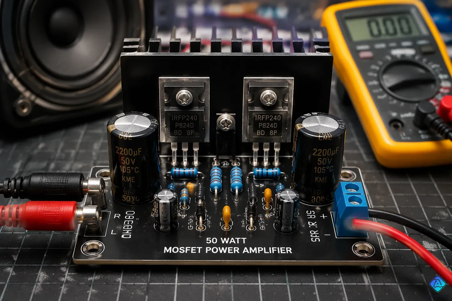
This 50 watt power amplifier joins a differential input pair, a driver stage, and complementary push-pull mosfets. A symmetric ±35V supply feeds the rails. The design gives 50W RMS into an 8 ohms load with low distortion.
You can expect distortion below 0.1% and flat audio-band response. Each mosfet stays cool on a large heatsink. This 50 watt audio amplifier fits a bookshelf system. The 50w rms audio amplifier works well for learners. Any audio amplifier build rewards patience.
The guide follows build order: circuit design, parts selection, assembly on Vero board or PCB, testing, and troubleshooting.
Mains voltage can kill. Ground the heatsink, and discharge filter capacitors before you touch the board.
Key Takeaways
-
Build a 50W amplifier with a differential input pair, a driver stage, and push-pull MOSFETs to get clear audio.
-
Use matched MOSFET pairs and a big heatsink so the current is shared evenly and the devices stay cool.
-
Use a star grounding setup and keep input wires short to stop hum and noise.
-
Test it with a current-limited supply. Set the bias to 20mV across the emitter resistors. This gives 30mA of quiescent current.
-
Do a dummy load test first before you connect speakers. This helps avoid damage and makes sure everything works right.
50 Watt Power Amplifier Circuit Overview
Design Goals and Topology
This 50 watt power amplifier aims for 50W RMS into an 8 ohms load. The design keeps distortion low and holds a flat frequency response across the audio band. The mosfets give the input stage a high impedance, so your source sees an easy load.
The topology is a classic discrete chain. A differential input pair compares the signal with the feedback. A driver stage then boosts voltage. Finally, a complementary push-pull output stage sends current to the speaker. This 50w rms mosfet audio amplifier uses lateral mosfets, and that choice shapes the bias behavior you will set later.
50 Watt Amplifier Circuit Diagram and Specs
The 50 watt amplifier circuit diagram shows three blocks in order: input pair, driver, and output stage. Look at the schematic diagram 50w rms audio amplifier builders often share, and you will see the same flow. The mosfet power amplifier section sits on the right, fed by symmetric ±35V rails.
| Parameter | Value |
|---|---|
| Output power | 50W RMS into 8 ohms |
| Supply voltage | ±35V symmetric |
| Distortion | Below 0.1% |
| Bandwidth | Flat across the audio band |
| Input impedance | High, set by the mosfet input |
| Speaker impedance | 8 ohms target; 6-ohm compatible with care |
This 50 watt rms output power amplifier using mosfets suits builders who want discrete control. A chip amp such as the LM3886 is a simpler path for beginners. The discrete mosfet audio amplifier rewards you with learning value instead.
How the 50W RMS MOSFET Audio Amplifier Works
Input and Driver Stages
The signal enters a differential input pair. One transistor takes your source signal. The other takes the feedback from the output. This pair compares the two and corrects any error. The feedback path sets the gain and keeps distortion low. A high input impedance matters here. The mosfets present an easy load to a preamp or phone. Your source does not sag under the load. That is why this 50w rms mosfet audio amplifier pairs well with simple sources.
The driver stage follows the input pair. It boosts the small voltage swing up to the level the output devices need. The driver also supplies the current that charges the gate capacitance of the output mosfets. Fast charging keeps the high frequencies clean. A weak driver smears transients. This 50 watt rms output power amplifier using mosfets uses a driver stage sized for that job.
MOSFET Output Stage and Bias
The output stage uses complementary mosfets in a push-pull arrangement. One device pulls the speaker up toward the positive rail. The other pulls it down toward the negative rail. This complementary push-pull pair shares the load. Each device handles half the waveform. The bias network sets a small standing current through both devices. That current keeps them conducting near the zero crossing. Without it, you hear crossover distortion as a harsh edge on quiet passages.
This build runs in class AB. Class A wastes power and runs hot. Class B is efficient but distorts at the crossover. Class AB sits between the two and suits a 50w rms amplifier that must stay cool on a reasonable heatsink. The bias current is the key setting. Set it too low and distortion returns. Set it too high and the mosfets overheat. You will adjust it during testing. A well-biased mosfet audio amplifier delivers the clean 50w rms into 8 ohms this design promises.
Building the 50 Watt Power Amplifier
Bill of Materials and Component Selection
Get all your parts before you start soldering. If a resistor is missing, the build stops halfway through.
| Part | Notes |
|---|---|
| Lateral power mosfets | One N-channel and one P-channel, a matched pair |
| Driver transistors | Small-signal types that boost voltage |
| Resistors | For the input pair, feedback, and bias network |
| Capacitors | 2000 µF filter value, plus small coupling and bypass parts |
| Diodes | Rectifier bridge and bias spreader |
| Vero board or PCB | The platform you pick |
| Heatsink and hardware | Screws, insulators, thermal paste |
Buy mosfet pairs that are matched and from the same batch. If the devices don't match, they share current unevenly and get hot. Check that capacitor voltage ratings can handle the ±35V rails, and leave some headroom. Pick resistors with tight tolerance for the input and feedback spots. If tolerance is loose there, your gain and bias will shift.
Power Supply, Heatsink, and Assembly
The supply begins with a transformer rated well above the 50w rms output. A bridge rectifier changes AC into DC. Filter capacitors smooth the ripple into clean symmetric ±35V rails. If the filtering is too small, you will hear hum through the 8 ohm speaker.
Size the heatsink for continuous output, not short bursts. Spread a thin, even layer of thermal paste. Mount each device flat and tighten the screws evenly. Insulate the tabs wherever the design calls for it.
Build on Vero board or PCB in this order:
-
Solder the smallest parts first: resistors, then diodes.
-
Add capacitors and the driver transistors.
-
Mount the power mosfets last, and wire them to the heatsink.
-
Keep input wiring short and away from output leads.
-
Run all ground returns to one central point.
This 50 watt power amplifier circuit pays off with a tidy layout. Clean grounding stops hum before it starts. The 50 watt power amplifier also needs a solid star ground at the supply.
Mains voltage can kill. Discharge the filter capacitors through a resistor before you touch the board, and bond the heatsink to earth ground.
Testing and Troubleshooting the 50 Watt Amplifier Circuit
Test and Bias Adjustment
Testing the 50watt amplifier circuit follows a set order. Skip a step and you could damage your speakers or your mosfets.
-
Unhook the speakers and turn the bias trimmer to its lowest setting, which is the highest resistance.
-
Power the amplifier through a current-limited supply, first set to about 200mA. Check that the DC offset at the speaker terminals stays under 50mV and that no oscillation shows up.
-
Switch to the final power supply with rail fuses. Check the DC offset at the speaker outputs again. It should not go above 50mV.
-
Measure the voltage between the emitters of the output transistors.
-
Turn the bias trim until this emitter-to-emitter voltage reads 20mV. That value matches a quiescent bias current of 30mA.
-
Check that the heatsinks stay no warmer than lukewarm. You can raise or lower the bias to your liking while you watch the temperatures.
-
For thermal safety, mount the driver and output devices on the same heatsink. Thermal coupling stops thermal runaway and serious damage to the output stage.
As a guide for picking a bias level, this design reports a simulated THD20k of 0.003% at 30% power when run at a moderate quiescent current of 45mA. Full-power 50W THD sits around 0.1%. That gives you context for deciding whether to stay near the 30mA setting or move up toward 45mA while watching heatsink temperature.
Run a dummy-load test before you connect any 8-ohm speaker. Feed a signal into a power resistor and watch the waveform. Only after the amplifier passes this test should you hook up a real 8 ohms load.
Troubleshooting and Upgrades
| Fault symptom | Check | Pass / fail criterion |
|---|---|---|
| DC offset | Output DC offset with grounded inputs | Acceptable below ±50mV; above 100mV points to a failed output transistor or bias resistor drift |
| Hum or noise | Noise floor on a scope, volume at minimum | RMS noise should stay below 2mV; higher noise suggests poor grounding or bad decoupling |
| Overheating | Device surface temperature at 50% rated power for 15 minutes | Should stay below 70°C; above 85°C signals inadequate heatsinking |
| Distortion or no output | Clipping onset with a 1 kHz sine | Clipping should begin at the input voltage matching the gain times input sensitivity |
For hum, use star grounding at one point near the supply filter caps. Shared ground paths between the input stage, power stage, and supply return create loops and hum. Thin power traces also heat up and drop voltage during transients, so keep power rails wide.
Optional improvements raise long-term reliability. Add a speaker protection board to guard your 8-ohm speaker against DC faults. A soft-start circuit limits the inrush current at power-on. Better filtering cuts leftover hum. An upgraded heatsink gives the 50 watt power amplifier more thermal margin for long listening sessions. Each upgrade builds on a working 50w rms audio amplifier, so finish testing first.
You now have a clear build path. Check the power supply first. Next, put the board together and look it over. Set the bias using a dummy load. Hook up your speakers last.
Four things decide success. Matched mosfets share current evenly. A medium heatsink with thermal paste keeps the devices cool. Clean grounding means short signal traces that stay away from power traces. Measure bias current with a multimeter in series with the supply; aim for 50–100 mA. Guessing the setting invites distortion.
Start with a current-limited supply. Careful setup turns a working 50 watt power amplifier into high-quality audio. This 50w rms audio amplifier is a solid platform for learning. The mosfet stage welcomes upgrades later.

Written by Jack Elliott from AIChipLink.
AIChipLink, one of the fastest-growing global independent electronic components distributors in the world, offers millions of products from thousands of manufacturers, and many of our in-stock parts is available to ship same day.
We mainly source and distribute integrated circuit (IC) products of brands such as Broadcom, Microchip, Texas Instruments, Infineon, NXP, Analog Devices, Qualcomm, Intel, etc., which are widely used in communication & network, telecom, industrial control, new energy and automotive electronics.
Empowered by AI, Linked to the Future. Get started on AIChipLink and submit your RFQ online today!
Frequently Asked Questions
Can I use this design with 4-ohm speakers?
No. This build targets 8 ohms, and the article notes 6-ohm compatibility only with care. A 4-ohm load draws more current than the output stage and heatsink are sized for. Stay at 8 ohms unless you upgrade the heatsink and verify the bias current again.
Why does my amplifier hum even after I set the bias?
Hum usually comes from grounding, not bias. Run every ground return to one star point near the supply filter capacitors. Keep input wiring short and away from output leads. Shared ground paths between stages create loops, and those loops pick up ripple as audible hum.
How do I know the bias current is set correctly?
Measure the voltage between the output transistor emitters. The article's procedure sets this to 20mV, which matches a quiescent current of 30mA. Watch the heatsink temperature as you adjust. If the devices run hot, lower the setting. Measure with a meter, never by ear.
What distortion should I expect at full output?
Expect roughly 0.1% THD at full 50W output. At lower power the figure drops sharply; the design reports about 0.003% at 20kHz and 30% power with a moderate bias current. Distortion rises if the mosfet pair is mismatched or the bias sits too low.
Is a chip amp easier for a first build?
Yes. The article names the LM3886 as a simpler beginner path. This discrete power amplifier suits builders who want control over the bias and the learning that comes with it. Either way, start with a current-limited supply and test before you connect speakers.