How to Select an HDMI Redriver or Retimer for High Speed Signal Integrity
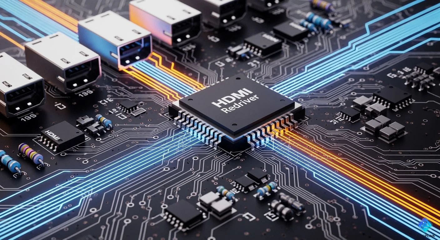
Pick an HDMI redriver for medium board trace lengths. Use it when signal overlap causes most line problems. Choose a retimer for longer traces or strict rules. A retimer resets both fixed and random signal jitter. Picking the best chip protects your fast HDMI signals. It works for HDMI 2.0 and HDMI 2.1. Balance signal loss at top speeds with jitter limits. Watch board power limits and total chip costs.
Key Takeaways
-
Pick an HDMI redriver for short connections.
-
It saves power and cuts overall costs.
-
Choose an HDMI retimer for long paths.
-
It cleans up jittery signals.
-
It also rebuilds clear video data.
-
Measure your total trace loss at high speeds.
-
Do this before picking an HDMI signal chip.
-
Run software tests to check signal quality.
-
Follow HDMI rules before building the board.
HDMI Redriver vs. Retimer: Core Differences
Learn key differences between signal tools today. They fix fast HDMI lines. Both parts save signals on weak boards. Yet, they work using different internal setups. They fix signal loss and timing issues.
Linear Equalization in Redrivers
An hdmi redriver acts like an analog amp. Board lines block fast signals. They cut high speeds faster than slow ones. This loss hides your fast data bits. It closes the signal eye shape fast.
Key Technical Takeaway: This tool boosts high speeds. It levels out channel performance fast.
These chips use special CTLE analog circuits. The inner CTLE boosts high speed parts. This action fixes board loss very quickly.
[ Input Signal with ISI ] ---> [ CTLE Analog Gain ] ---> [ Amplified Signal ]
This method gives you great design perks:
-
The simple path creates almost zero delay.
-
The simple chip uses very low power.
-
The tiny chip takes up small space.
Yet, simple amps have clear physical limits. An hdmi redriver boosts signals and noise. It cannot remove timing jitter from data. It passes all old jitter right along.
Clock and Data Recovery in Retimers
A retimer resets your system clock completely. It does not just boost old signals. This tool rebuilds data from scratch instead.
The chip uses a special CDR circuit. The CDR locks onto incoming signal edges. It grabs the clock and key bits. Then, DFE cuts out bad board noise.
How CDR Cleans Signals:
The inner PLL tracks your speed.
The CDR samples distorted data points.
The tool removes all bad jitter.
The retimer outputs clean new data.
Rebuilding the stream stops built-up phase noise. The receiver gets a fresh new signal. It gets maximum time and voltage space.
Latency, Cost, and Layout Trade-Offs
You must weigh key trade-offs now. Your choice changes power and real costs. It affects your circuit board space too.
| Selection Metric | Analog Equalization Device | Digital CDR Regeneration Device |
|---|---|---|
| Primary Function | Boosts high speed signals | Fixes clocks and rebuilds data |
| Jitter Reset Capability | None (it passes all jitter) | Full reset (it clears all jitter) |
| Signal Latency | Very fast (under one nanosecond) | Slow delay (takes many clock cycles) |
| Power Consumption | Low power (100 to 300 mW) | High power (up to 1.5 W) |
| BOM Cost | Low cost ($) | High cost ($$$) |
Pick a chip based on your layout:
-
Short to Medium Board Traces: Use an analog boost chip now. Use it when trace loss stays low. It saves power and cuts total costs.
-
Long Traces or Cables: Use a CDR chip for long paths. Use it when trace loss is high. It helps you pass strict HDMI tests.
Key Selection Criteria for Signal Integrity
Engineers check board traits first. They choose signal tools carefully. Your layout guides your choice. Select an amp or retimer.
HDMI Bandwidth and Data Rates
HDMI rules set speed needs. HDMI 2.0 reaches 6 Gbps. It uses TMDS lines daily. HDMI 2.1 hits 12 Gbps. It needs FRL tech instead.
Important Bandwidth Rule: Faster data speeds create big loss. Board trace losses jump fast.
Match devices to protect signals. High speed lines stay safe.
Insertion Loss and Trace Length
Long traces weaken fast signals. Copper lines cut power fast. Dielectric loss hurts signal strength. Skin effects cause problems too.
Trace Loss (dB) = Frequency (GHz) x Length (inches) x Loss Factor
A 3-inch trace loses little. Yet, 12-inch traces drop power. Calculate total loss at key speeds. This step protects your data.
Jitter Breakdown: Deterministic vs. Random
Two jitter types ruin signals:
-
Deterministic Jitter (DJ): Interference and distortion cause it. Simple chips fix predictable noise.
-
Random Jitter (RJ): Heat and chip noise cause it. Retimers rebuild clocks to clear it.
Equalization Types: CTLE vs. DFE
Tools clean incoming data differently. Continuous Time Linear Equalization boosts signals. It lifts high frequencies fast. Yet, it boosts noise too.
Decision Feedback Equalization fixes reflections well. It cleans signals without boosting noise. DFE works in three steps:
-
The tool reads the bit state. It spots a 0 or 1.
-
It calculates old bit interference. It uses tap weights ($b_k$).
-
It removes the guessed noise. Special math cleans the input.
y[n] = x[n] - SUM( b_k * y_hat[n-k] )
This smart loop clears reflections.
Power and Thermal Budgets
Part power changes heat plans. An analog hdmi redriver uses 200 mW. A retimer needs 1.5 W. Active CDR parts draw power. Small cases need low heat. Low heat keeps systems stable.
Selecting the Right HDMI Redriver or Retimer
Follow a clear plan now. Pick the best part for your board. Match board specs to datasheet limits. Protect your signals easily. Pass official tests on your first try.
Calculate Channel Loss at Nyquist Frequency
Find total signal loss first. Fast HDMI data moves very quickly. Test loss at the Nyquist point. This point is half your data rate. HDMI 2.0 hits 6 Gbps. Check its loss at 3 GHz. HDMI 2.1 FRL reaches 12 Gbps. Check its loss at 6 GHz.
Measure loss from sender to receiver. Count board paths, vias, and caps. Include all board connectors too. Board metals change loss at 6 GHz. See real material loss traits below:
| Trace Width (W) | Megtron 6 Insertion Loss (dB/in) | Standard FR4_LP Insertion Loss (dB/in) | Approximate Attenuation Factor (FR4 / Megtron 6) |
|---|---|---|---|
| 4 mil | –0.872 | –1.290 to –1.356 | ~1.48x – 1.55x lower loss |
| 6 mil | –0.683 | –1.085 to –1.134 | ~1.59x – 1.66x lower loss |
| 8 mil | –0.577 | –0.961 to –0.999 | ~1.67x – 1.73x lower loss |
| 10 mil | –0.508 | –0.891 to –0.924 | ~1.75x – 1.82x lower loss |
| 12 mil | –0.455 | –0.842 to –0.871 | ~1.85x – 1.91x lower loss |
Multiply line length by loss rates. Add small loss for each via. Add connector loss numbers next. Add all losses to find totals.
Evaluate RX Sensitivity and TX Output
Check channel loss against driver specs. Look at receiver input limits. HDMI needs solid voltage levels. This reads data bits correctly.
[ Driver Output Swing ] ---> [ Channel Insertion Loss ] ---> [ Target RX Sensitivity ]
Signals lose power along long lines. Voltage drops and timing gets messy. Calculate voltage at the receiver input. Add a chip if voltage drops.
Match Equalization Gain to Trace Loss
Pick equalizer settings for your loss. Modern chips offer adjustable CTLE levels.
An analog hdmi redriver gives 12 dB boost. Use it for medium line loss. Pick a retimer for big losses. Use it if loss hits 16 dB. The retimer CDR cleans bad timing. It rebuilds fresh output signals fast.
Simulation Tip: Run software tests before making boards. Import chip models into your tool. Check eye height and jitter limits. This step proves your design works.
  Uncompensated Eye Diagram          Equalized / Regenerated Eye
     (Closed Differential)              (Open Compliant Eye)

        XXXXXXX                            .-------.
      XX       XX                         /         \
     XX  CLOSED  XX         --->         |   OPEN    |
      XX       XX                         \         /
        XXXXXXX                            '-------'
Verify HDMI Compliance and Protocols
Check chip support for HDMI rules. HDMI 2.0 uses clock-forwarded TMDS. HDMI 2.1 uses four FRL lanes.
Ensure chips pass link training data. Devices trade key setup patterns first. A retimer must pass patterns cleanly. It must not break system handshakes.
Check final HDMI test rules today. The right chip keeps signals strong. It helps you pass all tests.
Pick a chip by checking board loss. Choose based on your signal needs.
Decision Framework:
HDMI 2.0 (TMDS) & Short Traces: Pick an hdmi redriver for low loss under 12 dB.
HDMI 2.1 (FRL) & Extended Channels: Pick a retimer for big loss over 16 dB.
An hdmi redriver gives a cheap analog boost for short paths. Yet, retimers fix bad timing before signals reach the receiver. Run test models to ensure board compliance before building.

Written by Jack Elliott from AIChipLink.
AIChipLink, one of the fastest-growing global independent electronic components distributors in the world, offers millions of products from thousands of manufacturers, and many of our in-stock parts is available to ship same day.
We mainly source and distribute integrated circuit (IC) products of brands such as Broadcom, Microchip, Texas Instruments, Infineon, NXP, Analog Devices, Qualcomm, Intel, etc., which are widely used in communication & network, telecom, industrial control, new energy and automotive electronics.
Empowered by AI, Linked to the Future. Get started on AIChipLink and submit your RFQ online today!
Frequently Asked Questions
When should you choose an HDMI redriver instead of a retimer?
Pick an hdmi redriver for medium PCB traces. Use it for low channel loss. Your total loss stays under 12 dB. This chip cuts total board costs. It uses much less power too. The chip boosts weak signal power. Use it with safe timing margins.
Can an HDMI redriver fix timing jitter in HDMI 2.1 designs?
No, redrivers cannot fix timing jitter. They only boost total signal voltage. They use basic linear equalization tools. You need a retimer for jitter. Use CDR on fast 12 Gbps lanes. It clears all bad jitter.
Does an HDMI retimer add latency to your video signal?
Yes, a retimer adds small delay. The inner CDR takes clock cycles. It samples and rebuilds data. This tiny delay stays very short. It will not hurt video streaming. Games run smoothly without issues.
How do you simulate HDMI channel signal integrity before board tape-out?
Run IBIS-AMI tests in software first. Load chip models into your tool. Set up total line losses. Check eye diagrams to test performance. Models check voltage and timing space. You verify setups before buying boards.