What Is a Ladder Diagram and How Does It Work
A Ladder Diagram helps you control machines with a simple picture language. You use it to program PLCs. PLCs are devices that run many automatic systems. The design looks like a ladder. It has two rails on the sides. The rungs show control instructions. This idea came from relay logic. Engineers used real relays for ON and OFF control.
| Year | Milestone Description |
|---|---|
| 1980 | Relay logic started in factories. Electromechanical relays were used for ON and OFF control. |
| 1980s | Factories moved from relay logic to PLCs. They needed better control systems. |
| 1980s | Ladder diagrams were made from electrical ladder diagrams. This made PLC programming easier. |
Today, ladder diagrams are used in almost all factories. About 80% of automation systems use them for PLC programming. If you want to work with modern automation, you must know how a ladder diagram works.
Key Takeaways
- A Ladder Diagram shows how machines decide what to do. It uses rails and rungs to display control logic. - Knowing the parts, like contacts and coils, helps you program PLCs well. - Ladder Diagrams make control steps easier to see and understand. This helps you design, fix, and talk about automation systems. - You can use Ladder Diagrams for easy ON/OFF controls. You can also use them for harder jobs by joining rungs and branches. - Learning to read and make Ladder Diagrams helps you work with new automation systems.
Ladder Diagram Basics
Definition and Structure
You can think of a Ladder Diagram as a picture that shows how machines make decisions. This diagram helps you program a PLC by using symbols that look like parts of an electric circuit. The layout looks like a ladder, with two vertical lines called rails and several horizontal lines called rungs. The rails show where the power comes from and where it goes. The rungs hold the instructions that control machines.
Here is a table that shows the main parts of a Ladder Diagram and what they do:
| Component | Description |
|---|---|
| Contacts | Let power pass if the input is in the right state. There are two types: normally open (NO) and normally closed (NC). |
| Coils | Show outputs that turn on when power reaches them. |
| Branches | Allow power to flow in more than one path, like an OR gate. |
| Timers | Delay turning things on or off. |
| Counters | Count how many times something happens. |
| Latches | Keep something on even after the input turns off. |
| Rails | Vertical lines that show the power supply. |
| Rungs | Horizontal lines that connect the rails and hold the logic. |
The diagram puts inputs on the left and outputs on the right. This makes it easy for you to see what needs to happen for a machine to work. Each rung works like a small rule. The PLC checks each rule from top to bottom and from left to right. This clear layout helps you understand and fix problems quickly.
Tip: The Ladder Diagram uses a visual style that matches old relay diagrams. This makes it easy for you to learn if you have seen relay logic before.
Evolution from Relay Logic
Factories used to control machines with relay logic. This meant using many wires and physical relays to turn things on and off. You had to connect each relay with wires, which made the system large and hard to change. If you wanted to change how a machine worked, you had to move wires or add new relays.
When you use a Ladder Diagram, you do not need to move wires. You write the control logic in the PLC using the diagram. This makes your work faster and easier. You can change the logic by editing the diagram on a computer. The PLC then follows the new rules right away.
Here is a table that shows the main differences:
| Feature | Relay Logic Hardware | Ladder Diagram Programming |
|---|---|---|
| Wiring | Needs lots of wires and relays | Only needs wiring for inputs and outputs |
| Logic Creation | Built with physical relays | Drawn in the PLC as a diagram |
| Complexity | Gets messy with many relays | Stays simple and clear |
| Execution | All relays work at the same time | PLC checks each rule one after another |
You get many benefits from using a Ladder Diagram. You can design control systems quickly. You can fix problems easily because you see the logic as a picture. You can also work with others better because everyone can read the diagram. This change has made factories safer, faster, and more flexible.
Note: Ladder Diagrams are best for simple ON and OFF control. If you need to do math or work with complex data, you may need other PLC languages.
How Ladder Diagrams Work
Logic Flow
You can picture the logic flow in a Ladder Diagram as a step-by-step process. The PLC follows a clear path to make decisions and control machines. The CPU starts by reading the status of all physical inputs, such as switches and sensors. It updates this information in its memory. The PLC then begins at the top left of the Ladder Diagram and works through each rung, moving from left to right and top to bottom.
Here is how the logic flow works in most PLCs:
-
The CPU checks the status of inputs connected to the I/O modules.
-
It starts at the first rung, reading from left to right.
-
If an input, like a push button, is activated, the PLC turns on the output, such as a relay or motor.
-
The CPU continues to the next rung, repeating the process for each instruction.
-
After reaching the last rung, the CPU returns to the top and starts again. This loop happens many times each second.
The Ladder Diagram lets you see the control process as a picture. You can follow the logic easily because the PLC checks each rung in order. This makes troubleshooting simple and helps you understand how the machine works.
The left-to-right, top-to-bottom order is important. Each rung’s output can affect the next rung. The PLC checks all conditions before moving to the next rung. Power flows from left to right, which matches how electricity moves in real circuits. This structure breaks complex logic into smaller parts, making it easier for you to manage.
Control Processes
You use Ladder Diagrams to control many types of machines and processes. The diagram handles both sequential and parallel tasks. Sequential control means the PLC completes one task before starting the next. Parallel control lets the PLC manage several tasks at the same time by using branches in the rungs.
Here are some common control processes you can implement:
-
Limit switches
-
Inductive proximity switches
-
Proximity sensors
-
Capacitive proximity sensors
-
Ultrasonic proximity sensors
-
Photoelectric sensors
These sensors help the PLC know what is happening in the system. For example, you can use a Ladder Diagram to control a conveyor belt. The PLC turns the motor on when a sensor detects an object. It stops the belt when the object reaches a certain point. The PLC repeats this process in a loop, making sure the system works in real time.
Ladder Diagrams also work well with modern PLC hardware and software. Most PLCs follow the IEC 61131-3 standard, which includes Ladder Diagram as one of the main programming languages. This standard helps you connect PLCs with other systems, such as SCADA, HMIs, and cloud platforms. You can see this integration in the table below:
| Aspect | Description |
|---|---|
| Modern PLCs | Connect with SCADA, HMIs, ERP, and cloud platforms for full automation. |
| Communication Protocols | Allow real-time data flow from machines to management systems. |
| IEC 61131-3 Standard | Standardizes programming languages, including Ladder Diagram, for better integration. |
Tip: You can use Ladder Diagrams to control simple ON and OFF actions or more complex tasks by combining rungs and branches. The visual style helps you understand and change the logic quickly.
Ladder Diagrams give you a clear way to control machines. You can manage both simple and complex processes by arranging the rungs and branches. The PLC keeps checking the logic, making sure your system responds to changes right away.
Ladder Diagram Components
Rails and Rungs
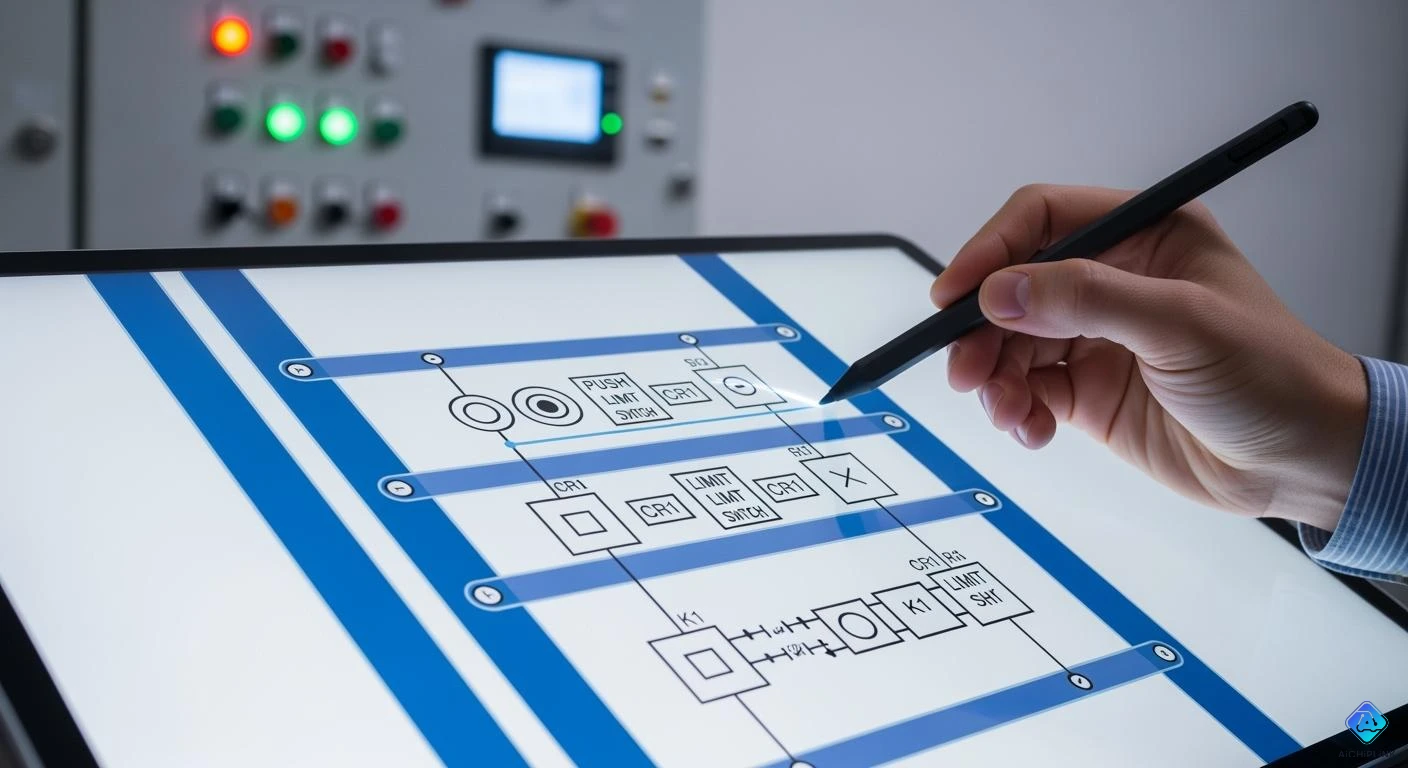
You can picture the rails and rungs as the backbone of any Ladder Diagram. The rails run vertically on each side of the diagram. The left rail connects to the power source, while the right rail connects to ground or neutral. The rungs stretch horizontally between the rails. Each rung holds the logic for one operation or rule. The PLC reads each rung from left to right, just like reading a sentence.
| Component | Function |
|---|---|
| Rails | Vertical lines that provide structure; the left rail is linked to the power source, and the right rail to the ground or neutral connection. |
| Rungs | Horizontal lines that contain the logic symbols defining operations or conditions in the control process. Each rung represents a single operation, with logic flowing from left to right. |
Tip: Think of the rails as the sides of a ladder and the rungs as the steps you climb. Each step is a new instruction for your machine.
Contacts and Coils
Contacts and coils help you control real-world devices using the Ladder Diagram. Contacts act like switches or sensors. You use two main types: normally open (NO) and normally closed (NC). A NO contact lets power pass when the input is true, like a switch that turns on a light. An NC contact lets power pass when the input is false, like a safety switch that stops a machine if opened. Coils sit on the right side of the rung. When energized, they turn on outputs such as motors or lamps.
| Component Type | Description |
|---|---|
| Contacts (NO) | Allow power to pass when the controlling input is true, like a closed switch. |
| Contacts (NC) | Allow power to pass when the controlling input is false, like a closed switch that stops power flow when open. |
| Coils | Represent outputs; when energized, they activate devices like motors or lights. |
-
Contacts show inputs such as switches and sensors.
-
Coils show outputs like motors and lights.
-
The order of these parts in the diagram matches how your system works.
Note: Placing the load device, such as a lamp or relay coil, on the right side of the rung helps ensure safe and reliable operation.
Common Symbols
You will see many symbols in a Ladder Diagram. Each symbol stands for a different part or action in your control system.
-
Contact symbols show the state of an input or output. You use normally open (NO) and normally closed (NC) contacts most often.
-
Coil symbols show outputs. You may see output coils, set coils, and reset coils.
-
Timer symbols look like a box with a "T" and a number. They control actions based on time.
-
Counter symbols help you count events, like how many times a button is pressed.
-
Other symbols show logic operations, such as AND, OR, or NOT.
Remember: Learning these symbols helps you read and create Ladder Diagrams quickly and accurately.
Applications of Ladder Diagrams
Industrial Automation
Ladder Diagrams are used in many factory systems. They help control machines and watch sensors. They also manage outputs very well. Ladder Diagrams started with relay-based systems. This makes them good for jobs that need safe and exact control. Ladder Logic checks switches, sensors, and output coils all the time. This helps keep machines safe and working right. It stops accidents and keeps the system running as it should.
Here is a table showing common things you can control with Ladder Diagrams:
| Functionality | Description |
|---|---|
| Counting Functions | Count up or down when inputs change. |
| Comparisons | Check if values are greater than, less than, or equal. |
| Timing Instructions | Manage delays for turning devices on or off. |
| Special Functions | Handle tasks like PID loops, shift registers, and communication. |
| Math Instructions | Perform calculations such as addition or subtraction. |
| Boolean Expressions | Use logic like AND, OR, and NOT for decision-making. |
Tip: Ladder Diagrams have worked well for many years in factories.
PLC Programming
Ladder Diagrams are a main way to program PLCs. This picture style makes it easy to design and fix control systems. Many engineers learn PLC programming by drawing Ladder Diagrams. They use these diagrams to set up automated systems. You can connect sensors, actuators, and control devices. You get to work with real hardware, like Siemens PLCs. This helps you see how sensors and actuators work together.
-
You can design and test full control systems.
-
You can use many sensors and actuators together.
-
You learn how to make sensors and actuators work as a team.
Other Uses
Ladder Diagrams are not just for factories. Some schools use them to teach automation basics. You might find them in building controls or water plants. They are even used in amusement park rides. Their simple style and clear logic make them good for any system that needs safe ON and OFF control.
Reading and Creating Ladder Diagrams
Interpreting Symbols
When you read a ladder diagram, you need to understand what each symbol means. Each symbol shows a part of the control system. You will see input symbols, output symbols, and special symbols like timers or counters.
-
Place input symbols on the left side of the rungs. These symbols show the conditions that must be met for the output to turn on.
-
Use series connections for AND logic. This means both conditions must be true for the output to activate.
-
Use parallel connections for OR logic. This means if either condition is true, the output will activate.
-
Put output symbols on the right side of the rungs. These symbols show the devices that turn on when the input conditions are met.
-
Add special symbols, such as timers and counters, for more complex tasks.
Tip: Always check that your symbols are in the right place. Input symbols go on the left, and output symbols go on the right. This helps you avoid mistakes and makes your diagram easy to read.
Common errors include putting symbols in the wrong place, missing logic steps, or adding extra operations that do not belong. If you keep your symbols organized, you will find it easier to follow the logic and fix problems.
Drawing Basics
You can start drawing ladder diagrams by learning the basic structure. A ladder diagram uses two vertical rails and several horizontal rungs. Each rung acts as a pathway for logic operations. This layout helps you see how the control flow moves from left to right.
Here are the seven basic parts you should know:
-
Rails
-
Rungs
-
Inputs
-
Outputs
-
Logic expressions
-
Address notation or tag names
-
Comments
When you draw, use clear labels for each input and output. Add comments to explain what each rung does. This makes your diagram easy for others to understand. Always check your logic for missing or conflicting steps. If you follow these basics, you will create ladder diagrams that work well and are easy to troubleshoot.
Ladder Diagram Example
Simple Circuit Example
You can start learning ladder diagrams with a basic circuit. Imagine you want to control a lamp with a push button. This setup works like a light switch in your room. When you press the button, the lamp turns ON. When you release the button, the lamp turns OFF. This is one of the simplest ways to use a ladder diagram.
-
A push button acts as the input.
-
A lamp acts as the output.
-
Pressing the button completes the circuit and lights the lamp.
Here is what the ladder diagram might look like:
|----[ ]----( )----|
     PB      LAMP
-
[ ]represents the push button (normally open contact). -
( )represents the lamp (output coil).
Tip: You can use this same idea to control other devices, such as motors or buzzers, by changing the output.
Step-by-Step Walkthrough
You can follow each step in the ladder diagram to see how the control process works. This step-by-step approach helps you understand how each rung acts as a rule for the PLC.
-
The PLC checks the push button input.
-
If you press the button, the contact closes.
-
Power flows from the left rail, through the closed contact, to the lamp coil.
-
The lamp turns ON as long as you hold the button.
-
When you release the button, the contact opens, and the lamp turns OFF.
This visual process shows you how the PLC reads each rung in order. Each rung acts as a logic pathway. You can see how the input (push button) controls the output (lamp) directly.
-
A step-by-step walkthrough makes complex automation logic simple.
-
You can use this method to train others or solve problems quickly.
-
Teams can work together better because everyone sees the same logic.
Note: Practicing with simple circuits helps you build confidence before moving to more advanced ladder diagrams.
You now know that ladder diagrams use rails and rungs to show how things work. The diagram has contacts, coils, timers, and counters. You can look at the table below to see the main ideas:
| Main Points | Description |
|---|---|
| Structure | Rails and rungs make up the diagram. |
| Components | Contacts, coils, timers, counters, and blocks. |
| Logic Functions | IF-THEN logic helps control machines. |
| Ease of Use | Easy to fix and keep working. |
Learning about ladder diagrams helps you fix problems and make safe systems. If you want to try it yourself, you can use guides like PLC Programming | How to Read Ladder Logic & Ladder Diagrams or PLC Ladder Logic Programming Tutorial (Basics).

Written by Jack Elliott from AIChipLink.
AIChipLink, one of the fastest-growing global independent electronic components distributors in the world, offers millions of products from thousands of manufacturers, and many of our in-stock parts is available to ship same day.
We mainly source and distribute integrated circuit (IC) products of brands such as Broadcom, Microchip, Texas Instruments, Infineon, NXP, Analog Devices, Qualcomm, Intel, etc., which are widely used in communication & network, telecom, industrial control, new energy and automotive electronics.
Empowered by AI, Linked to the Future. Get started on AIChipLink and submit your RFQ online today!
Frequently Asked Questions
What is the main purpose of a ladder diagram?
You use a ladder diagram to show how machines make decisions. It helps you control devices like motors and lights in an easy-to-read way.
Can you use ladder diagrams for complex tasks?
You can use ladder diagrams for many tasks. For very complex math or data work, you may need other PLC languages.
Why do ladder diagrams look like ladders?
Ladder diagrams look like ladders because they have two rails and rungs. The rails show power flow. The rungs show control steps.
Do you need special software to draw ladder diagrams?
You need PLC programming software to draw and test ladder diagrams. Most PLC brands give you their own software for this job.