How Millimeter Wave Radar Works: Principles and Components
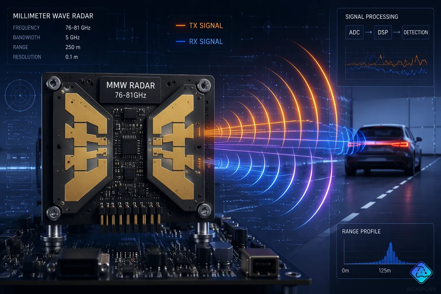
Millimeter wave radar works by sending out high-frequency electromagnetic waves and analyzing the reflected signals to detect objects and measure their distance, speed, and angle. Think of shouting in a canyon and listening for the echo. The working principle and key components are explained in simple terms. Mmwave radar sensors are growing quickly, and the global market is expected to grow from $4.7 billion in 2025 to $17.7 billion by 2035. Millimeter wave radar leads in automotive use. Mmwave radar sensors use FMCW technology, and they transmit chirps with the help of an antenna array. Range resolution and distance measurement are both very important. These sensors are everywhere and help improve safety. A mmwave radar system includes a processor, and another sensor detects objects. Millimeter wave radar sensors are small and accurate.
Key Takeaways
-
Millimeter wave radar uses radio waves to find objects and tell how far away, how fast, and at what angle they are.
-
It works well in bad weather like fog, rain, and snow, unlike cameras and LiDAR.
-
The radar sends out chirps and listens for the returning echoes to figure out distance and speed.
-
The main parts are a transmitter, antenna, receiver, and signal processor.
-
These tiny, cheap sensors make cars safer with features like collision avoidance.
Millimeter Wave Radar Basics
Frequency, wavelength, and bands
Millimeter wave radar operates in the 30–300 GHz frequency range. The wavelength spans 1–10 mm. These short wavelengths give mmwave radar sensors their unique capabilities. Engineers often choose 60 GHz and 77 GHz for automotive and industrial applications. Each band offers different trade-offs between range, resolution, and size.
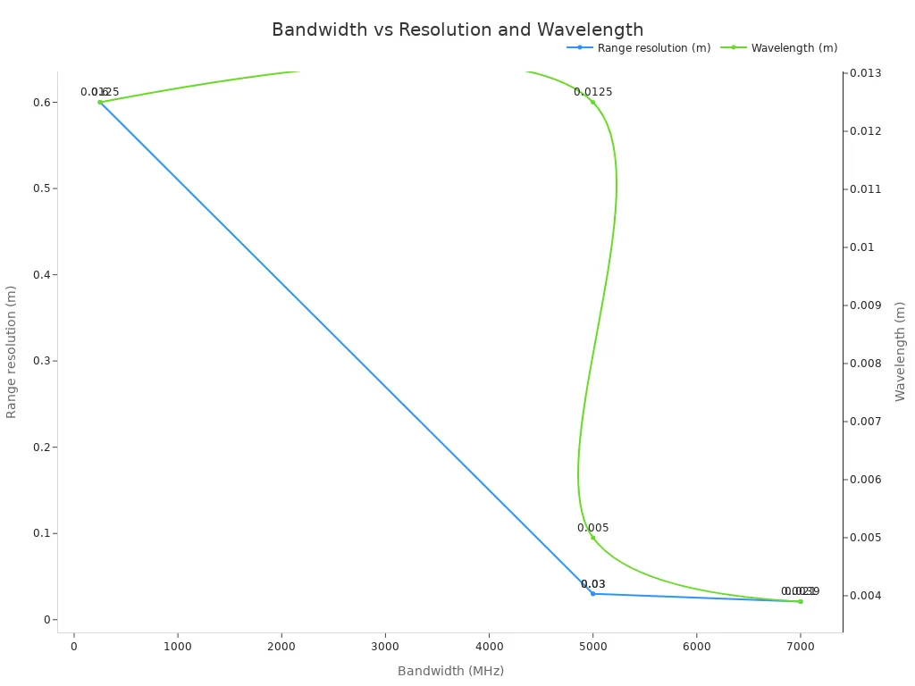
The table below shows the key frequency bands and their characteristics.
| Band | Frequency | Bandwidth | Range resolution | Wavelength | Primary use |
|---|---|---|---|---|---|
| 24 GHz narrowband | 24.0–24.25 GHz | 250 MHz | 0.6 m | 12.5 mm | Motion-only, low cost |
| 24 GHz UWB | 24.05–24.25 GHz | 5 GHz | 3 cm | 12.5 mm | High-precision motion |
| 60 GHz | 57–64 GHz | 7 GHz | 2.1 cm | 5.0 mm | Indoor presence detection |
| 77 GHz | 76–81 GHz | 5 GHz | 3 cm | 3.9 mm | Automotive, industrial |
Regulatory bodies allocate specific bands for different regions. The USA permits 24.0–24.25 GHz and 76–81 GHz. Europe and China follow similar standards. These allocations ensure mmwave radar sensors operate without interfering with other wireless services.
Why millimeter waves suit radar
Higher frequencies enable wider bandwidths. A wider bandwidth directly improves range resolution. At 60 GHz, a 7 GHz bandwidth delivers 2.1 cm range resolution. At 77 GHz, a 5 GHz bandwidth achieves 3 cm range resolution. These fine resolutions allow mmwave radar sensors to distinguish nearby objects clearly.
Shorter wavelengths also allow smaller antennas. A 60 GHz system with a 50 mm aperture achieves about 5.7 degrees angular resolution. A 24 GHz system with the same aperture only reaches about 14 degrees. This difference explains why 60 GHz and 77 GHz systems can resolve multiple occupants while 24 GHz typically cannot.
Weather resilience sets millimeter wave radar apart from optical sensors. Fog, rain, snow, and dust do not degrade radar performance. LiDAR struggles in these conditions. Cameras also lose effectiveness in low visibility. Mmwave radar sensors maintain reliable distance measurement and speed detection regardless of weather.
Cost and size favor millimeter wave radar sensors for mass deployment. They are compact and affordable. Automakers install them on grilles, sides, and rear sections. This flexibility supports full 360-degree coverage at low cost.
Working Principle of mmWave Radar
FMCW and time-of-flight for distance
The basic working idea of a millimeter wave radar sensor is simple. The device sends out a wave and listens for its return. Engineers call this method frequency-modulated continuous wave, or FMCW. Unlike pulse radar, which sends short bursts, FMCW radar sends a steady signal. It sends a chirp, which is a wave that rises in frequency over a short time. One sweep is called a chirp. The transmitter sends this chirp out, and the receiver catches the echo from objects.
The system then mixes the sent chirp with the received chirp. This mixing creates an intermediate-frequency (IF) signal. The IF signal is a sine wave with a frequency equal to the difference between the two input frequencies. For an object that is still, the IF signal has a steady frequency. That frequency is related to the round-trip delay. The round-trip delay is two times the distance divided by the speed of light. So range measurement boils down to measuring the IF signal frequency.
| Aspect | Operating Principle | How It Enables Measurement |
|---|---|---|
| FMCW transmission and mixing | The radar transmits frequency-modulated chirps and mixes them with the delayed echo. The mixer outputs an IF signal. | Creates a stable IF signal for extracting range and velocity. |
| Range measurement | For a stationary object, the IF signal is a sine wave with constant frequency. | Range comes from the IF frequency, which is proportional to round-trip delay. |
| Velocity measurement | The phase of the IF signal changes with small distance shifts across chirps. | Velocity comes from the phase difference between consecutive chirps. |
A simple example can help. Think about shouting in a canyon. The time between your shout and the echo tells you how far the canyon wall is. FMCW radar does the same with radio waves. The IF signal frequency acts like that echo delay. A higher IF frequency means a farther object. This method gives millimeter wave radar sensors their reliable distance measurement ability.
The IF signal has a phase equal to the difference between the phases of the sent and received signals. When we see the IF signal as a peak in the spectrum, we are only seeing part of the picture—the signal's strength. The peak also has a phase value that matches the starting phase of the IF signal.
Doppler effect for speed
Speed measurement uses the Doppler effect. When an object moves toward the radar, the reflected wave gets compressed. When it moves away, the wave gets stretched. This change in frequency shows the object's speed. The formula for radar Doppler shift is fd = 2v times ft divided by c, where v is the target's speed toward the radar, ft is the sent frequency, and c is the speed of light. Since v is much smaller than c in most cases, this is easy to handle.
A group of chirps, called a frame, lets us find speed. If the object moves between chirps, the IF signal's FFT peak changes in phase. The phase difference between chirps shows the Doppler shift. A Range FFT finds distance from each chirp. A Doppler FFT across chirps finds speed. This separates the two measurements. Range and speed estimation happen at the same time in FMCW mmwave radar sensors.
Real-world conditions create limits. Range-Doppler coupling causes signal overlap and errors in distance and speed. Fast-moving targets can go beyond the clear speed range, causing aliasing. Multipath reflections from metal areas create fake signals. Low signal-to-noise ratio lowers estimate reliability. Temperature and oscillator drift cause errors without calibration. Multiple moving objects need advanced separation methods. These factors guide how engineers design and use FMCW technology in real life.
Key Components of Millimeter Wave Radar Sensors
Transmitter, antenna, and receiver
Every mmwave radar sensor has three main parts: a transmitter, an antenna system, and a receiver. The transmitter makes the chirp signal. A synthesizer creates this chirp. The transmitter then sends the signal to the transmitting antenna. That antenna sends the signal outward. On the other side, the receiving antenna picks up the echo from objects. A mixer inside the receiver combines the received signal with the sent signal. This mixing forms an IF signal. The IF signal holds information about detected objects.
Antenna choice changes based on what the system needs. Engineers pick from microstrip patches to horns depending on size, weight, and how much power they must handle. The millimeter-wave band lets engineers pack more antennas into a small space and get higher gain. A special material called a metamaterial radome protects the antenna array but still lets signals pass through. Lab tests showed a gain increase of about 7 dB in transfer coefficient. Chamber tests showed a gain improvement of about 5 dB for a 24 GHz array antenna. The receiving antenna must catch even very weak echoes reliably.
How much power the transmitter outputs depends on the driver and power-amplifier stages, the operating frequency, bandwidth, linearity, modulation type, heat design, and available DC power. Two important power measures are the 1 dB compression point and saturated output power. The 1 dB compression point matters most when the signal needs to stay linear.
The RF transmitter signal path goes through clear steps. IF or baseband input enters the transmitter. Frequency generation uses a stable local oscillator. Upconversion changes the signal to millimeter-wave frequency. Filtering and amplification remove unwanted parts and boost the desired signal. The RF output sends the final signal to the antenna. The RF receiver path works in reverse. Low-noise amplification boosts weak signals while keeping extra noise low. Filtering cuts out interference from other signals. Downconversion changes the RF signal back to IF or baseband. The processed output then goes to demodulation, digitization, or analysis.
Manufacturers group mmwave radar sensors into three types: long-range, medium-range, and short-range. Long-range radar works from 10 to 250 meters with a narrow ±15 degree view. It helps with autonomous cruise control. Medium-range radar works from 1 to 100 meters with a ±40 degree view. It helps with lane changes and collision avoidance. Short-range radar works from 1 to 30 meters with a wide ±80 degree view. It handles blind spot detection and parking help. Engineers pick the right sensor for each job. Knowing these groups helps when choosing a millimeter wave radar for specific tasks. Different millimeter wave radar sensors play different roles in modern cars. These mmwave radar sensors cover many uses from highway driving to parking.
Signal processor and supporting components
Other analog parts are very important for mmwave radar performance. Clock generators like the VCO and PLL add frequency offset and phase noise. These problems get worse when the phase-locked loop does not fully lock during frequency modulation. The ADC adds its own quantization noise and phase noise. These flaws lower measurement accuracy. The quality of the IF signal depends a lot on these analog parts.
The digital signal processor handles radar signal processing. It does fast Fourier transforms and Doppler filtering to track targets even when there is clutter or electronic countermeasures. The DSP processing chain has several steps. The digital up converter does interpolation, digital filtering, and frequency translation. The DAC changes digital IF samples to analog. The analog down-converter and ADC turn the reflected echo into digital form. The digital down converter uses mixing, low-pass filtering, and decimation to get back the baseband I/Q signals. The DSP then uses pulse compression, Doppler processing, CFAR detection, and target tracking to get range and velocity. Every mmwave radar sensor uses this processing chain. These mmwave radar sensors keep getting smaller while doing more. Different mmwave radar sensors focus on different needs.
Various algorithms keep improving detection accuracy. A CNN-based method with overlapping detection beats regular CFAR limits in high-resolution settings. Another method gets 92 percent accuracy for classifying people, cars, and bicycles using root radar cross section and support vector machines. Most mmwave radar sensors use CFAR for reliable detection.
Antenna array design directly affects angular resolution and range resolution. One design with a peak gain of 32 dBi at 77 GHz gets a 3 dB beamwidth of 2.5 degrees and sidelobe suppression below -20 dB. The APPS method picks out targets that are very close in angle, with an angle difference of about 0.5 degrees. It uses a MIMO radar with 3 TX and 4 RX antennas, making a virtual array of 12 elements. More elements makes it easier to tell targets apart. Array design directly affects how well the system estimates angle and overall angular resolution.
All parts work together inside the mmwave radar sensor. The transmitter creates the chirp. The antenna sends and receives. The receiver mixes and downconverts. The ADC turns the IF signal into digital numbers. The DSP processes those numbers to get range, velocity, and angle. This chain lets mmwave radar sensors give reliable distance, speed, and angle measurements. The full signal reception and processing chain turns raw reflections into useful information about the environment.
How a Millimeter Wave Radar Sensor Works Together
From transmission to detection
A millimeter wave radar sensor goes through a clear order from making a signal to finding an object. The transmitter sends a frame of chirps, and each one has a set bandwidth and duration. The sent chirp moves outward and bounces off objects around it. The receiver picks up this echo signal and mixes it with the sent chirp. This mixing makes an IF signal with a frequency tied to the target range.
The processing chain then pulls out information one step at a time. An ADC samples the IF signal to build a data cube. A first FFT along the fast-time dimension gives range information. A second FFT across chirps measures phase shifts to find velocity. A CFAR detector then finds real targets and cuts down noise. This workflow lets mmwave radar sensors make point clouds with range, velocity, and angle data. The range resolution depends on the chirp bandwidth, so wider bandwidths tell closer objects apart.
Angle detection with antenna arrays
Angle detection depends on several antenna elements working as a team. A MIMO design uses n transmit and m receive antennas to make n×m virtual pairs. Each pair measures a slightly different distance to the same target. By looking at phase shifts between pairs, the system works out the direction of arrival.
More antenna elements make the beamwidth narrower and improve angular resolution. A non-MIMO setup with four receive elements gives about 30 degrees beamwidth. A MIMO setup with seven virtual elements cuts this to about 17 degrees. This gain lets mmwave radar sensor systems tell apart two objects 25 degrees apart that would otherwise look like one. The antenna array therefore plays a key role in angular measurement. All parts work as a team to turn raw reflections into a clear picture of the surroundings.
Millimeter wave radar sends out high-frequency waves and studies the echoes to find distance, speed, and angle. The transmitter makes the chirp, the antenna sends and receives signals, the receiver mixes echoes, and the signal processor pulls out target data. FMCW timing makes distance measurement dependable.
These mmwave radar sensors mix small size with strong performance. A millimeter wave radar sensor gives accurate results even in bad weather. Mmwave radar sensor designs keep getting better. Engineers trust mmwave radar sensors for safety systems. Mmwave radar sensors will shape everyday technology. Millimeter wave radar sensors will become more common in daily life. Millimeter wave radar will keep making the world safer and smarter.

Written by Jack Elliott from AIChipLink.
AIChipLink, one of the fastest-growing global independent electronic components distributors in the world, offers millions of products from thousands of manufacturers, and many of our in-stock parts is available to ship same day.
We mainly source and distribute integrated circuit (IC) products of brands such as Broadcom, Microchip, Texas Instruments, Infineon, NXP, Analog Devices, Qualcomm, Intel, etc., which are widely used in communication & network, telecom, industrial control, new energy and automotive electronics.
Empowered by AI, Linked to the Future. Get started on AIChipLink and submit your RFQ online today!
Frequently Asked Questions
What makes millimeter wave radar different from cameras and LiDAR?
Cameras and LiDAR do not work well in fog, rain, snow, and dust. Millimeter wave radar still works in these conditions. It also measures distance and speed on its own. This is why automakers trust it for safety systems.
Which frequency bands do mmwave radar sensors use?
Most mmwave radar sensors work between 30 and 300 GHz. The 24 GHz, 60 GHz, and 77 GHz bands are common picks. The USA allows 24.0–24.25 GHz and 76–81 GHz. Europe and China have similar rules.
How does a millimeter wave radar sensor measure distance and speed at the same time?
The transmitter sends a chirp, and the receiver mixes the echo with it. The intermediate-frequency signal that comes out carries range data. Phase shifts between chirps show velocity through the Doppler effect. This fmcw method gives both measurements at once.
Why do mmwave radar sensors need multiple antennas?
One antenna cannot measure direction. An antenna array with several elements catches tiny phase differences between received signals. A MIMO setup with 3 TX and 4 RX elements makes 12 virtual pairs. This design narrows the beamwidth and sharpens angular resolution.
What limits the accuracy of mmwave radar sensors?
A few things lower accuracy. Range-Doppler coupling causes errors in distance and speed estimates. Fast targets cause aliasing past the clear speed range. Multipath reflections from metal surfaces make false signals. Temperature and oscillator drift add errors without calibration.