Does the Terminal Resistance of the CAN Bus Have to Be 120Ω?
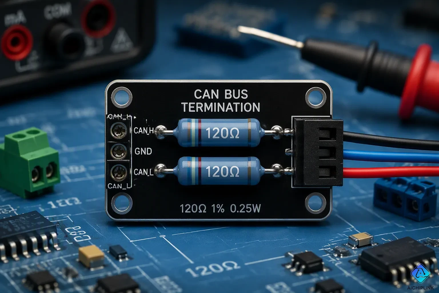
No, the terminal resistance of the CAN bus is not a strict rule. It is the standard requirement for reliable communication in most systems. This 120Ω value matches the characteristic impedance of the twisted-pair cable. Matching impedance stops signal reflections that would corrupt data. Understanding this principle helps engineers make smart choices when they need to deviate from the norm. Some low-speed CAN bus systems use different termination values, but these cases require careful checking. The correct termination depends on bus length, speed, and application requirements. The termination value must match the cable's characteristic impedance. High-speed CAN networks especially need proper termination to maintain data integrity. Typical networks benefit most from sticking with 120Ω as the safest approach.
Key Takeaways
-
Standard CAN bus uses two 120Ω resistors at both ends of the cable to match the characteristic impedance and stop signal reflections.
-
High-speed CAN networks need exact 120Ω termination; wrong values cause bit errors and bus failures.
-
Low-speed or short-distance CAN buses might work with different termination, but engineers must test and check how well they perform.
-
Use a multimeter to check the termination resistance—a working bus reads about 60Ω between CAN High and CAN Low.
Why the Terminal Resistance of the CAN Bus is 120Ω
The 120-ohm value is not random. The ISO 11898 standard requires it, and this rule is still needed in 2025. Two 120 ohm resistors at each physical end of the bus create the right load. Each 120 ohm resistor connects between CAN High and CAN Low. This setup gives a total bus resistance of about 60 ohms when you measure across the two lines. The industry chose this value because it matches the cable's impedance. Engineers did not get it from pure theory. They measured real automotive twisted-pair cables and found the characteristic impedance was about 120 ohms. This real-world result became the rule.
Preventing Signal Reflection
A signal moving along a CAN bus acts like a wave in a pipe. When the wave hits the end of the cable, it meets a sudden change. Without proper termination, the energy bounces back toward the source. This bounce creates ringing, overshoot, and undershoot. The reflected waveform piles on top of the original signal. Transmission quality then gets worse. A 120 ohm resistor at each end soaks up this energy. The resistor turns the reflected energy into heat. This stops the echo from ruining data. The reflection coefficient decides how much energy bounces back. An open circuit reflects positively. A short reflects negatively. A matched impedance causes no reflection at all. Each 120 ohm resistor matches the line, so the signal sees no break. The bus signal stays clean. This rule works for all high-speed CAN bus systems. Proper termination keeps signal integrity across the network.
Matching Characteristic Impedance
Characteristic impedance is the fixed ratio between voltage and current for a traveling wave. A standard CAN bus cable has a characteristic impedance of 120 Ω ±10%. The 120 ohm resistor matches this value. When the load impedance equals the line impedance, energy moves fully into the load. Nothing bounces back. This match is key for reliable communication. A mismatch makes part of the signal bounce back like an echo. The incident wave and reflected wave then interfere with each other. This interference twists the data. Engineers use two 120 ohm resistors to terminate both ends of the bus. Each 120 ohm resistor connects between CAN High and CAN Low. The two 120 ohm resistors in parallel make the 60-ohm total. A single 60-ohm resistor can replace them on a small network.
If you don't have two 120-ohm resistors, you can accomplish the termination (on a small network) with a single 60 ohm resistor(120 in parallel with 120 is 60) or anything close 55-65 is fine.
The 120-ohm value became the industry standard because it matches the cable's impedance. This match cuts down attenuation and distortion. It ensures reliable communication over long distances. The terminal resistance of the CAN bus therefore plays a vital role. It keeps can bus terminal resistance at the correct value. Any deviation from 120 ohms risks harming the signal. The can bus terminal resistance must match the cable's impedance for the network to work. Two 120 ohm resistors remain the default choice. Each 120 ohm resistor gives the right load at its end. The 120 ohm resistor value is not optional for standard high-speed CAN. It is the base of dependable data exchange.
What Happens If You Use Different Values?
Wrong resistor values mess up communication on any CAN network. The damage gets worse as bus speed goes up. A 1M baud rate link fails completely without proper termination. A 125K link sometimes works. A 40K link often works fine. This pattern shows that high-speed CAN bus systems rely heavily on correct termination. Signal reflections happen whenever the termination does not match the cable's impedance. Those reflections corrupt data frames and cause errors.
| Baud Rate | Proper Termination | Communication Success |
|---|---|---|
| 1M | Yes | Yes |
| 1M | No | No |
| 125K | Yes | Yes |
| 125K | No | Sometimes |
| 40K | Yes | Yes |
| 40K | No | Yes |
Risks of Higher Resistance
A resistor value above 120 ohms leaves the bus under-terminated. The termination no longer matches the cable's impedance. Some signal energy bounces back toward the transmitter. This echo messes with the original waveform. The receiver then has a hard time telling dominant bits from recessive bits.
Pulling termination during a live session shows this fast. The transmitter logs Bit Errors right away. A Bit Error happens when a node sends one bit value but reads back a different one. The receiver logs Bit Stuffing Errors at the same time. A Stuff Error occurs when six equal bits in a row appear on the bus. These errors keep going until someone puts termination back. Repeated bit errors quickly raise the Transmit Error Counter. Once that counter passes a threshold, the node enters bus-off state and stops talking completely. Missing termination resistors, too many terminators, or wrong resistor values all lead to this result.
Risks of Lower Resistance
A value below 120 ohms creates the opposite problem. Extra current flows through the bus. A single terminator pulls twice the current a transceiver is built to deliver. This overload can shorten the transceiver's lifespan.
Over-termination makes things worse. Three 120 ohm resistors in parallel give 40 ohms. Four give 30 ohms. The transceiver must then supply much more current to drive the dominant state. This current draw causes a bigger voltage drop across the transceiver's internal output stage. CAN_H drops to roughly 3.0 V. CAN_L rises to about 2.0 V. The differential voltage shrinks from the normal 2.0 V to around 1.0 V. That smaller swing directly cuts noise margin and signal integrity.
Only the two physical end nodes should carry termination resistors. Adding termination at middle nodes puts extra resistors in parallel. This lowers total bus resistance below the needed 60 ohms. The lower resistance overloads the CAN transceiver outputs and weakens the signal. Communication breaks down quickly.
A differential load resistor can be added to increase the anti-interference capabilities of the bus while it is recessive, with the resistance value as low as feasible to avoid the influence of most of the noise energy. However, the resistance should not be too low to avoid requiring too much current from the bus to become dominant.
Designers sometimes add a differential load resistor to boost noise immunity during the recessive state. This trick works only within limits. Too low a value forces the bus to source too much current just to reach the dominant state. The trade-off between noise rejection and drive current needs careful calculation. Proper termination always balances these competing needs. Two 120 ohm resistors remain the safe default for standard high-speed networks. Any other value needs testing and verification before deployment.
When to Deviate from CAN Bus Terminal Resistance
Standard high-speed CAN networks need 120 Ω at both ends. Some situations allow different values. Engineers must understand the trade-offs before making changes.
Low-Speed and Fault-Tolerant CAN
Low-speed CAN bus systems often use a different termination plan. Each node has its own termination resistor on the transceiver. These resistors sit on the data lines, not on the cable itself. This design does not try to match the cable's impedance. Instead, every node gives its own load. The table below shows the main differences.
| Aspect | High-Speed CAN | Low-Speed CAN |
|---|---|---|
| Termination resistors | Two 120 Ω resistors at both ends | One resistor per data line at each node |
| Placement | On the cable ends | On the transceiver |
| Purpose | Match characteristic line impedance | Each node has its own termination |
| Bus requirement | Only end nodes need termination | Every node requires termination |
Fault-tolerant CAN systems use the same method. They handle wiring faults better than high-speed CAN. This flexibility comes from spread-out termination. A broken wire at one point does not kill the whole bus. Engineers who design these systems accept lower speeds in return for this strength. The terminal resistance of the CAN bus in these networks serves a different purpose. It does not need to match the cable's impedance exactly.
Short-Distance Applications
Short cables change the picture. A very short bus may work without exact termination. Signal reflections travel back quickly. They arrive before the receiver samples the bit. This timing hides the reflection problem. Many bench tests and small prototypes run fine this way.
Going away from standard values still carries risk. A short bus at low speed might handle a missing resistor. The same bus at high speed will likely fail. Engineers must check performance through testing. They should look for bit errors and signal quality. Proper termination remains the safest choice. Any change requires careful measurement. The can bus terminal resistance should stay close to the standard unless testing proves otherwise. Reliable communication depends on this discipline. Signal integrity in can bus systems relies on matching the cable's impedance. Even short runs gain from correct termination. Engineers who skip this step risk on-and-off failures. These failures waste time and money during debugging.
Verifying CAN Bus Termination
Measuring CAN Bus Resistance
A technician can check the terminal resistance of the can bus with a basic multimeter test. First, turn off all power and disconnect the battery. Next, find the DLC (OBD-II port), but don't test there because it is a tap, not a break point. Then unplug a central module (like the ECM or gateway) to split the network into two legs. Set the multimeter to Ohms and probe between Pin 6 (CAN_H) and Pin 14 (CAN_L) at the DLC. With the module unplugged, one leg should read about 120 ohms (it has a terminator), and the other reads OL (no terminator). When you plug it back in, the reading should be about 60 ohms. A healthy bus with two 120 ohm resistors in parallel gives roughly 60 ohms, within about +/- 2 ohms. A reading near 120 ohms means one 120 ohm resistor is missing. An open circuit reading means both 120 ohm resistors are gone or the circuit is broken. A reading in the kiloohm range points to a termination problem, like a missing 120 ohm resistor, a wrong jumper or switch position, damaged wiring, or a disconnected device. This test protects signal integrity across the network.
Installation Rules for Terminal Resistance
Only two bus termination resistors belong in a CAN network, one at each physical end of the main trunk. Both termination resistors must sit on the physical ends of the CANBUS. If they are not at the physical ends, the effectiveness of the termination filtering resistors is negated. Common mistakes include using the wrong number of termination resistors, using the wrong resistance value, placing resistors in the wrong location, omitting termination resistors entirely, and incorrectly verifying termination resistance. A 120 ohm resistor must appear at each end, and each 120 ohm resistor must connect between CAN High and CAN Low. Some CAN bus devices have built-in 120-ohm termination that should be disabled if the device is not at the end of the bus. Correct resistor placement keeps proper termination intact. Proper termination supports reliable communication on can bus systems. Two 120 ohm resistors remain the standard. A 120 ohm resistor at a middle node adds an unwanted parallel load. A 120 ohm resistor in the wrong spot weakens the bus. A 120 ohm resistor at each end preserves integrity. A 120 ohm resistor value of 120 ohms matches the cable. A 120 ohm resistor pair gives 60 ohms total. A 120 ohm resistor check confirms proper termination. A 120 ohm resistor test ensures communication works.
The 120Ω value is not the only choice you can make for CAN bus termination. It is still the safest and most reliable option for standard high-speed CAN networks. Engineers who go away from this standard must calculate and test their design carefully. This step makes sure signal integrity stays intact across the network.
Any change to the terminal resistance of the can bus needs verification. Proper termination supports reliable communication in can bus systems. Designers should put standard compliance first unless specific constraints justify a different approach. This discipline protects data quality and prevents costly debugging. Reliable can networks depend on this careful balance.

Written by Jack Elliott from AIChipLink.
AIChipLink, one of the fastest-growing global independent electronic components distributors in the world, offers millions of products from thousands of manufacturers, and many of our in-stock parts is available to ship same day.
We mainly source and distribute integrated circuit (IC) products of brands such as Broadcom, Microchip, Texas Instruments, Infineon, NXP, Analog Devices, Qualcomm, Intel, etc., which are widely used in communication & network, telecom, industrial control, new energy and automotive electronics.
Empowered by AI, Linked to the Future. Get started on AIChipLink and submit your RFQ online today!
Frequently Asked Questions
How many termination resistors does a CAN bus need?
A standard high-speed CAN bus needs exactly two termination resistors. You should place one 120 ohm resistor at each physical end of the main trunk. If you add a third resistor in the middle, it creates a parallel load. That extra load drops the total resistance below the required value and makes the signal weaker.
What resistance should a multimeter show on a healthy CAN bus?
A healthy bus with both terminators connected reads about 60 ohms between CAN High and CAN Low. This value comes from two 120 ohm resistors in parallel. If you read near 120 ohms, one terminator is missing. If you read an open circuit, both are gone.
Can a CAN bus work without termination resistors?
A very short, low-speed bus sometimes works without terminators. The reflections arrive before the receiver samples each bit. High-speed networks fail completely under the same conditions. Engineers should always test any design that skips proper termination. Reliable communication depends on matching the cable impedance.
What happens if a device has built-in termination in the middle of the bus?
A device with built-in 120-ohm termination adds an unwanted parallel load when you place it mid-bus. You should disable that internal resistor. Only the two physical end nodes should carry termination. This rule keeps total bus resistance at the correct value.
Does a lower baud rate allow different termination values?
Lower baud rates handle missing or incorrect termination better than high-speed links. A 40K bus often works without terminators. A 1M bus fails right away. Engineers who go against the standard must check signal integrity through testing. They should never assume a low-speed bus will always work.