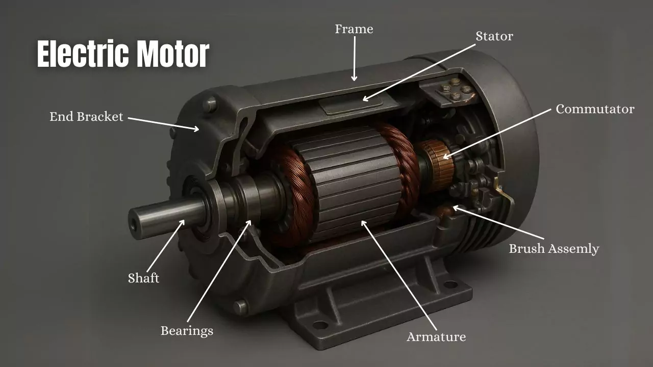
A typical DC motor contains several essential dc motor parts. These include the stator, which consists of the yoke, field windings, poles, and pole shoes. The rotor, also called the armature, works with the commutator, brushes, shaft, and bearings to form the basic components of a dc machine. Each part has unique functions that help convert electrical energy into motion. For example, copper coil windings in the stator increase electromagnetic field strength, improving torque. The rotor connects to the shaft, which transfers rotational force. The commutator and brushes maintain current direction, enabling smooth operation. The shaft rotates within bearings, supporting the rotor and allowing efficient movement. Together, these dc motor components deliver reliable performance, with output power reaching up to 238 W at room temperature but dropping to 172 W as the shaft temperature rises. The efficiency of a dc motor depends on how well these parts work together, especially the shaft, which appears in every stage of the energy transfer process.
| DC Motor Part | Basic Function |
|---|---|
| Stator | Provides stationary magnetic field |
| Rotor (Armature) | Rotates to produce mechanical motion |
| Commutator | Reverses current direction for continuous rotation |
| Brushes | Transfer current to the rotating commutator |
| Shaft | Transmits mechanical power from rotor to load |
| Bearings | Support shaft and reduce friction |
Key Takeaways
-
A DC motor has key parts: the stator creates a magnetic field, the rotor (armature) spins to produce motion, and the commutator with brushes keeps the current flowing correctly for smooth rotation.
-
The shaft transfers the motor’s mechanical power to external devices, while bearings support the shaft and reduce friction for quiet, efficient operation.
-
Each part works together to convert electrical energy into mechanical energy, making the motor run efficiently and reliably.
-
Regular maintenance of brushes, bearings, and the shaft helps extend the motor’s life and keeps it running smoothly.
-
Understanding these parts and their roles helps anyone grasp how a DC motor functions as a complete, coordinated system.
DC Motor Parts Overview
A DC motor relies on several essential components to convert electrical energy into mechanical motion. Each part plays a specific role in this process. Understanding these dc motor parts helps explain how the machine operates efficiently.
Stator and Its Role
The stator forms the stationary part of the dc motor. It includes the yoke, poles, pole shoes, and field windings. The yoke provides mechanical support and houses the magnetic poles. Field windings, made of copper coils, generate a uniform magnetic field when current passes through them. This magnetic field interacts with the rotor to produce motion. Technical reports, such as those from NASA, describe the stator's ability to operate at peak current and withstand thermal and electromagnetic stresses. The stator ensures the magnetic environment remains stable, which is crucial for efficient energy conversion.
Note: The stator's field windings create the magnetic field that enables the armature to rotate, making it one of the most important dc motor components.
Rotor (Armature) Function
The rotor, also called the armature, rotates inside the stator. It contains the armature winding, which consists of copper coils wound around a laminated core. As current flows through the armature winding, it interacts with the stator's magnetic field, producing torque and causing the shaft to turn. Quantitative studies show that different rotor designs can affect torque, efficiency, and power factor. For example, one analysis found that a specific rotor design achieved up to 18% higher torque and an efficiency of 88.49% at rated points. The rotor's structure and electromagnetic behavior directly influence how well the dc motor converts electrical energy into mechanical energy.
-
The shaft connects to the rotor, transmitting rotational force to external loads.
-
Bearings support the shaft, allowing smooth and efficient rotation.
Commutator and Brushes
The commutator and brushes work together to maintain the direction of current in the armature windings. The commutator consists of insulated copper segments attached to the rotor. Carbon brushes stay in contact with these segments, conducting current from the external circuit into the rotating armature. As the rotor spins, the commutator reverses the current direction in the windings, ensuring continuous torque and smooth rotation. Studies highlight the importance of proper brush spring tension and current density to prevent rapid wear and maintain stable operation. The interaction between the commutator and brushes forms a complete electrical circuit, which is fundamental to the performance of all basic components of a dc machine.
Tip: Keeping the shaft, commutator, and brushes in good condition helps extend the life of the dc motor and ensures reliable performance.
Summary Table of Essential Components of a DC Machine:
| Component | Function |
|---|---|
| Stator | Provides stationary magnetic field using field windings |
| Rotor (Armature) | Rotates to convert electrical energy to mechanical energy |
| Armature Winding | Carries current, interacts with magnetic field |
| Commutator | Reverses current direction in windings |
| Brushes | Conduct current between external circuit and commutator |
| Shaft | Transmits mechanical power from rotor to load |
| Bearings | Support shaft, reduce friction |
Stator Components
Yoke
The yoke forms the outer frame of the stator in a dc motor. It provides mechanical strength and protects the internal parts from damage. The yoke also serves as a path for magnetic flux, helping to complete the magnetic circuit. Engineers often select materials with high magnetic permeability for the yoke to ensure efficient flux retention. A case study examined how changing the yoke width affects magnetic flux. Increasing the yoke width beyond a certain point did not improve the torque constant, while reducing it caused a drop in performance. This result highlights the yoke’s critical role in maintaining magnetic flux and supporting the overall efficiency of the dc motor. The yoke and bearings together ensure the stator remains stable during operation.
Field Windings
Field windings wrap around the poles of the stator and create the magnetic field necessary for motor operation. When current flows through these windings, they generate a strong and uniform magnetic field. The field winding of a dc machine uses copper wire to maximize conductivity and minimize losses. Researchers use numerical methods and simulation-based tests to measure the resistance and reactance of these windings. These tests help engineers assess the performance of the stator and detect faults such as short circuits or open windings. In some applications, such as off-grid water pumping, comparative studies show that different winding configurations can reduce torque ripple and improve efficiency. The windings play a vital role in the reliability and performance of the dc motor.
Poles and Pole Shoes
Poles and pole shoes attach to the yoke and support the field windings. The poles concentrate the magnetic field, while the pole shoes spread the field evenly across the air gap between the stator and rotor. This design ensures smooth and efficient operation. Technical evaluations use computer models and finite element simulations to analyze the performance of poles and pole shoes. These studies measure electromagnetic torque, current, and losses due to eddy currents. They also simulate temperature rise at the pole shoes, which can affect motor performance. Engineers use these results to optimize the design of poles and pole shoes, balancing factors such as inductance, leakage, and heat dissipation. The yoke and bearings work together with the poles to keep the stator aligned and stable.
Tip: Regular inspection of the windings and pole shoes can help prevent overheating and extend the life of the dc motor.
Stator Function in DC Motor
The stator acts as the stationary part of the dc motor, providing the magnetic environment needed for the rotor to turn. It consists of the yoke, field windings, poles, and pole shoes, each with a specific function. Researchers use finite element simulations to analyze the electromagnetic field inside the stator. These studies predict magnetic flux distribution, electromotive force, and torque. They also evaluate how winding configurations and magnetic flux affect efficiency and power density. Optimization techniques help engineers maximize output torque and minimize losses. The stator’s design directly influences the performance, reliability, and efficiency of the dc motor. The field winding of a dc machine, along with the windings on the poles, ensures that the magnetic field remains strong and stable throughout operation.
-
The stator supports the windings and maintains the correct alignment of all internal parts.
-
It provides a path for magnetic flux and helps dissipate heat generated during operation.
-
The stator’s structure, including the yoke, poles, and windings, determines the overall effectiveness of the dc motor.
Rotor (Armature) and Shaft
Armature Structure
The armature forms the rotating core of a dc motor. Engineers design the armature with a laminated core made from cold rolled grain-oriented silicon steel. This material reduces energy losses caused by eddy currents and improves magnetic performance. The armature winding, made of copper wire, wraps around the core in precise patterns. These windings carry current and interact with the magnetic field from the stator. The armature winding connects to the commutator, which helps maintain the correct direction of current flow.
-
Modifications to the rotor, such as using shoe-shaped pole tips and increasing shaft length, have shown improved mechanical power transmission and better magnetic performance.
-
Ventilation holes in the motor covers help cool the armature and windings, preventing overheating during operation.
-
Engineers often use a stepped shaft design to physically separate the motor and pump, which eliminates the need for seals and prevents fluid from entering the motor. Field trials over 18 months confirmed that this design prevents fluid leakage.
The armature winding plays a critical role in the conversion of electrical energy to mechanical energy. The yoke and bearings support the armature, keeping it aligned and stable as it rotates. The role of the armature is central to the operation of every dc motor.
Shaft and Bearings
The shaft connects directly to the rotor and extends through the motor housing. This component transmits the mechanical power generated by the rotor to external devices, such as gears or pumps. Engineers have experimented with increasing shaft length to improve power transmission and reliability. A stepped shaft design can separate different functional sections, such as the motor and pump, by about 20 mm. This separation eliminates the need for dynamic or static seals and prevents fluid ingress, as proven by long-term field trials.
Bearings support the shaft and allow it to rotate smoothly with minimal friction. Low-noise bearings and specialized lubricants reduce mechanical noise and vibration, making the dc motor quieter and more stable. The yoke and bearings work together to keep the shaft and rotor properly aligned. Shaft grounding devices, such as carbon brushes and shaft-grounding rings, protect bearings from electrical damage. These devices provide a safe path for stray currents, extending the lifespan of the bearings and improving motor reliability.
Tip: Regular preventive maintenance, including dust removal, lubrication, and inspection of brushes, helps extend the life of the shaft and bearings. Predictive maintenance using electrical test equipment can identify potential failures before they occur, reducing downtime and repair costs.
Operating temperature also affects the efficiency and lifespan of the shaft and bearings. Heat from electrical resistance, magnetic losses, and friction can degrade lubricants and insulation. Modern dc motors use ventilation, fan cooling, and thermal sensors to manage temperature and protect these critical components.
Rotor’s Role in DC Motor
The rotor, which includes the armature and shaft, serves as the heart of the dc motor. It rotates within the magnetic field created by the stator windings. The armature winding on the rotor carries current, and the interaction between this current and the magnetic field produces torque. This torque turns the shaft, delivering mechanical power to external loads.
Quantitative studies highlight the impact of rotor design on motor performance. For example, a tangential interior air-isolated injection molded rotor structure improved several key metrics compared to a traditional design:
| Performance Metric | Traditional Magnetic Isolation Bridge Structure | Tangential Interior Air-Isolated Injection Molded Rotor Structure | Improvement (%) |
|---|---|---|---|
| Back Electromotive Force Coefficient | Baseline | 14.5% higher | +14.5% |
| Torque Coefficient (Nm/A) | 0.0253 | 0.0312 | +21.7% |
| Viscous Damping Coefficient (Nm/(rad/s)) | 0.00318 | 0.00456 | +43% |
| Motor Power at Rated Torque (0.9 Nm) (W) | 250 | 275 | +10% |
Mechanical strength simulations confirm that the integrated rotor structure withstands high operational loads, such as centrifugal force and magnetic pull at 5500 rpm. This design improves both performance and durability.
-
Field trials with modified permanent magnet arrangements in the stator produced a weaker net magnetic flux, which increased motor speed and mass flow rate in pump applications.
-
Carbon brush assemblies with proper spring tension ensure reliable electrical contact, reducing voltage drops and improving overall efficiency.
The rotor, together with the shaft, transforms electrical input into useful mechanical output. The armature winding, windings, and shaft all contribute to the efficient operation of the dc motor. Proper design and maintenance of these components ensure long service life and optimal performance.
Commutator and Brushes in DC Motor
Commutator Function
The commutator in a dc motor acts as a rotary switch. It reverses the direction of current in the armature windings every half turn. This reversal keeps the torque produced by the motor in a single direction, allowing continuous rotation. Engineers design the commutator with copper segments insulated from each other. Interpoles help control current reversal in the coils, which reduces sparking and improves performance. During operation, brushes span several commutator segments, so multiple coils enter different stages of commutation at once. This design helps transfer stored energy and minimizes arcing. Proper brush pressure and angle ensure good electrical contact and reduce wear. Observations of minimal sparking and smooth torque confirm that the commutator works as intended.
To confirm proper commutator function, technicians often perform these steps:
-
Spin the motor shaft by hand to check inertia and friction.
-
Short the terminals and spin the shaft again to observe damping.
-
Measure resistance with a multimeter, noting changes with shaft angle.
-
Power the motor and measure current while stalling the shaft.
-
Use an oscilloscope to observe back-EMF signals while spinning the shaft.
-
Connect encoder channels to the oscilloscope and check pulse timing.
-
Power the motor with a battery pack and calculate no-load speed.
-
Mechanically couple two motors, power one, and measure the passive motor’s speed and back-EMF.
These tests confirm that the commutator delivers smooth torque and maintains good electrical contact.
Brushes Function
Brushes in a brushed dc motor transfer electrical current from the external circuit to the rotating commutator. Most dc motors use carbon brushes in a dc machine because carbon provides good conductivity and resists wear. The brush must maintain steady contact with the commutator segments to ensure reliable operation. Engineers assess mechanical factors such as brush holder dimensions, spring force, and brush stability. Electrical factors include minimizing resistance in the brush holder circuit to prevent heat buildup and uneven wear. Regular maintenance, such as checking spring force and brush position, helps extend brush life.
Technical assessments use accelerated life testing to simulate stresses like torque, speed, and temperature. Data from these tests undergo statistical analysis, such as Weibull distribution, to estimate brush durability and predict motor lifespan. These methods help engineers improve the reliability of carbon brushes in a dc machine.
Tip: Regular inspection and adjustment of brush holders and springs can prevent early failures and maintain efficient operation.
Interaction Between Commutator and Brushes
The interaction between the commutator and brushes is essential for the operation of a brushed dc motor. As the rotor turns, the brushes slide over the commutator segments, transferring current to the armature windings. This contact allows the commutator to reverse current direction at the right moment, keeping the motor’s torque steady. The use of carbon brushes in a dc machine helps form a lubricating film on the commutator surface, which reduces friction and suppresses sparking.
A well-designed system ensures that brush pressure, angle, and material all work together to maintain stable electrical contact. If the brush pressure is too low, contact becomes unreliable, leading to arcing and rapid wear. If the pressure is too high, the brush and commutator wear out faster. Engineers optimize these factors to achieve long-lasting performance in every dc motor.
| Component | Role in DC Motor Operation |
|---|---|
| Commutator | Reverses current direction, enables rotation |
| Brushes | Conduct current, maintain contact with commutator |
Note: The quality of interaction between the commutator and brushes directly affects the efficiency and lifespan of a brushed dc motor.
How Essential Components of a DC Machine Work Together
Step-by-Step Operation
A dc motor transforms electrical energy into mechanical motion through a series of coordinated actions. Each part plays a specific role in this process:
-
The armature receives electrical energy and generates electromagnetic force. This force interacts with the magnetic field to produce torque, which starts the rotation.
-
The commutator reverses the current direction in the armature windings. This action keeps the rotation continuous and smooth.
-
Brushes transfer current to the commutator while maintaining contact. Their lifespan depends on the load, ranging from 750 to 7,500 hours.
-
Field windings or permanent magnets create the magnetic field. Permanent magnets offer higher efficiency and less maintenance, while field windings allow for adjustable torque.
-
The shaft carries mechanical energy from the rotor to external devices. Motor efficiency usually falls between 70% and 90%. Key performance parameters include speed, current, torque, efficiency, and output power.
-
Bearings support the shaft and reduce friction. The choice of bearing depends on speed and load requirements.
-
The frame and end caps provide structure and protection, keeping all internal parts stable.
Regular maintenance of these parts helps ensure reliable operation and extends the life of the dc motor.
Summary of Interactions
The essential components of a dc machine work together in a tightly coordinated system. Technical manuals and simulation studies show that each part interacts through electrical and mechanical relationships. For example, the stator supplies voltage and creates a magnetic field, while the armature carries current and generates torque. The commutator and brushes maintain the correct current direction, supporting continuous rotation. The rotor’s movement depends on the balance between electromagnetic torque, load torque, inertia, and damping. Engineers use mathematical models to describe these interactions, including equations for voltage, current, back electromotive force, and torque. Simulation and hardware-in-loop tests confirm that these relationships determine the overall performance and efficiency of the dc motor.
A well-designed system ensures that all parts operate in harmony. This coordination allows the motor to deliver consistent power, high efficiency, and long service life.
A DC motor depends on several key parts, each with a unique function. The stator creates the magnetic field. The rotor interacts with this field to produce motion. The commutator and brushes ensure continuous rotation and reliable energy transfer. The shaft delivers mechanical power to the load.
-
Test bench experiments confirm that every component—stator, rotor, commutator, and brushes—directly affects torque, efficiency, and reliability.
-
Regular maintenance and quality materials help each part perform under real-world conditions.
Remembering these basic roles helps anyone understand how DC motors work as a complete system.
FAQ
What is the main function of the stator in a DC motor?
The stator creates a stationary magnetic field. This field interacts with the rotor, allowing the motor to convert electrical energy into mechanical motion.
Why do DC motors use brushes and a commutator?
Brushes and the commutator work together to reverse current direction in the armature winding. This process keeps the motor spinning smoothly and maintains continuous torque.
How do bearings affect DC motor performance?
Bearings support the shaft and reduce friction. Good bearings help the motor run quietly and efficiently. Worn bearings can cause noise, vibration, and lower efficiency.
Can a DC motor work without field windings?
Some DC motors use permanent magnets instead of field windings. These motors still create a magnetic field but do not allow for adjustable torque like wound-field designs.
Tip: Regular maintenance of brushes and bearings extends the life of a DC motor.
Written by Jack from AIChipLink.
AIChipLink, one of the fastest-growing global independent electronic components distributors in the world, offers millions of products from thousands of manufacturers, and many of our in-stock parts is available to ship same day.
We mainly source and distribute integrated circuit (IC) products of brands such as Broadcom, Microchip, Texas Instruments, Infineon, NXP, Analog Devices, Qualcomm, Intel, etc., which are widely used in communication & network, telecom, industrial control, new energy and automotive electronics.
Empowered by AI, Linked to the Future. Get started on AIChipLink.com and submit your RFQ online today!