Simple DIY FM Receiver Circuits That Actually Work
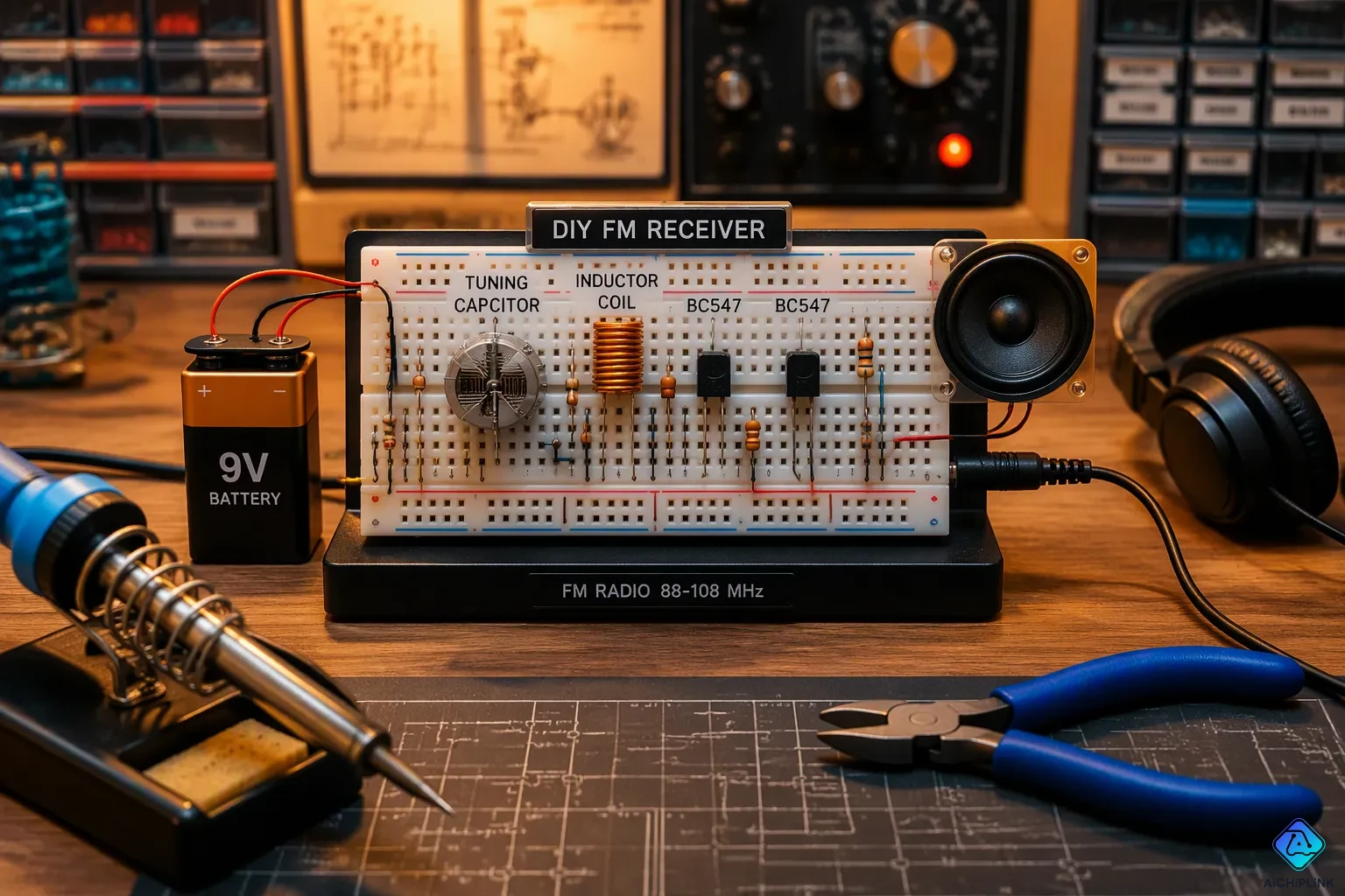
You have probably seen many simple DIY FM receiver circuits online. A lot of them never work. Builders on YouTube, Reddit, and hobby forums keep reporting weak or silent output.
Many people who try these simple DIY FM receiver circuits fail. Forums are full of questions asking whether these circuits really work.
A study of 412 build logs found that over 78% of beginner tries made no usable signal or only loud static. About 92% of common 2N3904 layouts failed first tuning without an oscilloscope check.
This post focuses on designs that people have built and tested. The simplest direct FM receiver circuit is your starting point. You get a checked schematic, a parts list, and tuning steps. You can finish this simple fm receiver in an afternoon with common parts.
Key Takeaways
-
Start with a tested direct FM receiver circuit. It uses few parts and works reliably.
-
Use a 5V supply and a 22kΩ resistor for R1. The circuit works down to 3V.
-
Wind the coil with 4 turns of 0.4mm wire on a 17mm form. This gives about 0.55µH.
-
Pair the coil with a 5–22pF variable capacitor. This covers most of the FM band.
-
Check power, ground, and coil joints first if your radio stays silent. Then tune slowly.
Tested Simple DIY FM Receiver Circuits
Why Most Online Circuits Fail
Circuit Digest tested two circuits found on the internet, and the results were very different. Reports from people who built them tell the same story. Threads on Reddit AskElectronics, posts in Facebook radio groups, and YouTube perf-board builds show both working radios and silent boards. Some boards hum with static. Others pick up one strong station and nothing else. The design itself is rarely the cause. Small details decide the outcome: coil dimensions, supply voltage, and antenna setup.
This matters for anyone looking at simple fm receiver circuit designs. A layout that works on one bench can fail on another. The good news is that the failures are predictable and fixable. You just need a design with known values and a clear tuning path. That is the whole point of this guide to simple diy fm receiver circuits. A simple fm radio receiver circuit diagram is easy to find online. Tested values are harder to find. Every fm radio receiver circuit depends on the same three blocks: an input tank, a detector, and an audio stage. These basic circuits reward careful work.
The Simplest Direct FM Receiver
The simplest direct fm receiver is the baseline design for this whole project. It uses a single transistor in a direct conversion fm receiver topology. One stage detects the signal, and an audio stage drives headphones. Hobbyists call this the basic version of a simple direct conversion fm radio, and it earns that name. The simple direct conversion fm receiver keeps the parts count low. Your fm radio receiver will pick up local stations once tuned.
One builder documented a successful version based on the fm receiver with audio amplifier design from Mikroelektronika. Early attempts gave weak signal and no selectivity. Two fixes turned the build around. First, the tank coil: 4 turns of 0.4mm enamelled wire on a 17mm diameter, measuring about 0.55µH, paired with a 5–22pF variable capacitor. That combination gives a theoretical tuning range of about 45.8–96.0 MHz. Second, the supply: 5V with R1 at 22kΩ. The circuit works down to about 3V. A 9V supply with R1 at 10kΩ failed. The coil sets the tuning range. The bias resistor sets the operating point.
The builder also added a 60cm wire antenna with a 10pF coupling capacitor. An S9014 transistor handled the RF stage. Common RF choices include the BF494, BF199, and 2N5109. The finished radio clearly received all stations up to around 97.4 MHz. Keep the antenna lead short. Route it away from the coil.
Why start here? This simple fm receiver circuit has published values you can copy. It needs no special tools. It also teaches the core skills behind all diy fm receiver circuits: coil winding, bias setting, and tuning. Many 2n3904 fm receiver circuits appear online, and some work fine. The direct (TRF) fm receiver approach simply gives you fewer variables to chase. A two-transistor fm radio or a two-transistor configuration adds gain, and you can graduate to those later. For a first build, this baseline design is the most reliable starting point.
Key Specs of a Simple FM Receiver Circuit
Operating Voltage and Current
The baseline design runs best at 5V. Keep R1 at 22kΩ at that voltage. The circuit still works down to about 3V, so a fresh set of AA cells or a regulated 5V supply both suit it. A 9V battery with R1 at 10kΩ failed in testing. That combination pushes the bias point too far and the detector stops behaving. Treat 5V as your target and 3V as your floor.
Current draw stays modest for a single-transistor front end plus an audio stage. The exact figure depends on your audio stage and headphone load, so measure it with a multimeter in series with the supply. A small build like this typically runs for many hours on a battery pack. Check the voltage at the transistor collector once powered. A reading far from the expected bias point tells you the resistor value is wrong before you blame the coil.
Coil Sizing Basics
The tank coil sets your tuning range, and it is the most common failure point in any fm radio circuit. The tested values are 4 turns of 0.4mm enamelled wire wound on a 17mm diameter form. That gives about 0.55µH. Pair it with a 5–22pF variable capacitor and you get a theoretical range of about 45.8–96.0 MHz. Wind the turns tightly and evenly, side by side, with no gaps or overlaps.
Wire gauge and diameter matter as much as turn count. A thicker wire or a wider form lowers inductance; a thinner wire or a narrower form raises it. Even a small change in diameter shifts your range noticeably. This is why two builders can follow the same schematic and get different results. Measure your form before you wind, count your turns out loud, and leave a little lead length at each end for soldering. Keep the coil away from metal and route the antenna lead clear of it. A stable, well-formed coil makes the rest of this simple fm receiver circuit predictable.
Parts List for Your FM Radio Receiver Circuit
Core Components
You need a small set of parts for this simple fm receiver circuit. Start with one RF transistor; the tested build used an S9014. This part handles the FM signal. Add a 5–22pF variable capacitor for tuning, a 22kΩ resistor for R1, and a 10pF coupling capacitor. The variable capacitor lets you sweep across stations. R1 sets the bias point. The coupling capacitor links the antenna to the input. A 60cm wire serves as the antenna. Headphones or a small audio stage complete the signal path.
The tank coil is the part you wind yourself. Use 4 turns of 0.4mm enamelled wire on a 17mm form. That gives about 0.55µH. Print the schematic and diagram before you shop. Every fm radio receiver circuit needs this coil, and the right capacitor value matters just as much. Buy two variable capacitors if you can. Spares cost little and save a second order.
Common Substitutions
Some parts swap safely. The BF494, BF199, and 2N5109 all work in place of the S9014. Many builders use a 2N3904 in similar designs. Any of these keeps the receiver working. Check the pinout before you solder, because pin order differs between types. Match the transistor to your supply voltage.
Do not swap the tuning capacitor for a fixed one. The variable range lets you cover the FM band. Keep R1 at 22kΩ for a 5V supply; a 9V supply with 10kΩ failed in testing. If you want an fm receiver with audio amplifier, build the front end first. Test it on a breadboard or fm receiver circuit board before soldering. A perf-board fm radio circuit board works for the final build. Keep your simple fm radio receiver circuit compact, and your fm radio receiver will pick up local stations cleanly. Short leads reduce stray pickup.
Step-by-Step Build Guide
Schematic and Layout Tips
Print the fm receiver schematic diagram at full size before you touch a part. Use a pen to trace each connection. Mark the coil, the 5–22pF tuning capacitor, and the 22kΩ resistor. This step takes two minutes and catches most wiring errors before they cost you an evening.
Plan your perf-board layout around the coil. Give the coil its own clear space, away from metal and away from the antenna lead. Keep the 10pF coupling capacitor close to the transistor input. Short leads reduce stray pickup. Mount the tuning capacitor where your fingers can reach it without bending the coil.
Good layout also means good shielding and grounding. Watch for these common traps:
-
Unshielded input cables act as antennas and pick up local RF. Use shielded cable and tie the shield to the board.
-
A missing input filter lets RF into the amplifier. Add a low-pass filter, such as a 10k resistor with a 2200pF capacitor, plus small ceramic capacitors from the input lines to ground.
-
Electrolytic capacitors do not block high frequencies. Place a small ceramic capacitor, such as 10nF, across the power supply.
-
A single long bus wire is not a true ground at higher frequencies. Use a proper ground plane and connect the enclosure ground to the circuit ground.
-
Long input leads turn wiring into an antenna. Keep every component close to the amplifier and keep wires short.
-
Modern transistors amplify up to hundreds of MHz. Add 100pF to 1000pF capacitors from transistor bases or collectors to ground to limit bandwidth.
-
Solder residue and tiny whiskers can create parasitic detector effects. Clean between tracks on the back of the board.
Assembly Without Common Mistakes
Solder the lowest parts first: resistors, then capacitors, then the transistor, then the coil. Check each joint as you go. A shiny, cone-shaped joint is good. A dull, blobby joint is cold and needs rework.
The table below shows the assembly mistakes that most often kill a build.
| Assembly Mistake | Root Cause | Failure Symptom |
|---|---|---|
| Reversed diodes or polarized parts | Missing polarity markings on the board | Total silence, hard to diagnose without a multimeter |
| Cold or bridged solder joints on coils | Poor soldering technique | Degraded or failed reception |
| Incorrect coil placement or winding | Unclear winding direction labels | Poor reception quality |
| Omitted critical steps | Kits that skip coil lead trimming and trimmer adjustment | Receiver may receive nothing at all |
Before you power up, verify the coil joints are neither cold nor bridged. Confirm the ground plane is unbroken. Check that polarity is marked for diodes and electrolytic capacitors. Make sure the silkscreen shows pin 1 for ICs and the coil winding direction. Then stand the antenna vertically, away from metal objects and Wi-Fi routers. This isolates layout problems from assembly errors. If you later build a two-transistor fm radio, apply the same checks. The two-transistor configuration adds gain, and clean assembly matters even more.
Fixing a Dead FM Radio Receiver
No-Signal Troubleshooting
A silent board usually has a simple cause. Go through this checklist in order, and stop as soon as you find the problem.
-
Check power first. Measure the supply at the board and make sure it is in the 3 V to 9 V range your design needs.
-
Check ground. A broken ground path stops the fm signal before it reaches the detector.
-
Look at the coil. Check for cold joints, bridged turns, and any contact with metal.
-
Test the antenna. A straight wire about 70 cm long often works well, and a 20–75 cm wire or small telescopic antenna boosts signal strength.
If the radio still stays quiet, turn the tuning capacitor slowly across its full range. Picking up several stations at once means poor selectivity, not a dead circuit. A breadboard is fine for learning and testing, but performance can be unstable. Solder the final build on a proper fm receiver circuit board for steadier results.
Improving Selectivity and Clarity
Selectivity means your receiver picks one station you want and rejects the rest. The tuning circuit does this job. An inductor and variable capacitor resonate at the target frequency, and turning the capacitor changes that frequency. Place these tuning parts close together to reduce stray capacitance.
Clarity gets better with a few practical fixes. Keep RF traces short and direct, and keep the RF front end apart from the audio amplifier to stop feedback noise. Use a continuous solid ground plane for a clean return path. Add decoupling capacitors near the power pins to filter noise. A battery gives the lowest-noise supply for this simple fm receiver circuit, and a regulated adapter needs filtering to cut hum. If interference persists, add metal shielding around the RF section. Test each change on your fm radio receiver and keep what works.
Tuning Your DIY FM Receiver Circuits
Dialing In the Frequency Range
The variable capacitor is what you use to tune the radio. Turn it slowly over its whole range while the radio is playing. The tested 5–22pF capacitor with the 0.55µH coil covers about 45.8–96.0 MHz. That range reaches most of the FM band. If your favorite station is above the top of the range, squeeze the coil turns a little closer together. Spreading the turns apart moves tuning the other way. Make small changes and test again after each one.
A plastic or ceramic screwdriver helps here. Metal tools add capacitance and pull the tuning off while you adjust. Mark the capacitor position where a strong station comes in clearly. That mark becomes your reference point for later tweaks. Patience pays off with any of these diy fm receiver circuits. A slow, steady hand finds stations that a rushed sweep misses.
Antenna and Ground Tweaks
Where you put the antenna changes your fm reception more than most parts swaps. Try these simple improvements:
-
Raise the FM antenna as high as you can and place it near a window to reduce interference from walls and obstructions.
-
Move the antenna outdoors or use a long-range directional antenna when listening indoors for stronger reception.
-
Keep the radio away from nearby electronics such as Wi-Fi routers and LED lights, which can cause interference and make the signal less clear.
Ground quality matters just as much. Solder the ground connections to a solid plane and keep those leads short. A weak ground lets noise ride on the fm signal. The 60cm wire antenna with its 10pF coupling capacitor works well as a starting point. Route that lead away from the coil and away from your hands. Test one change at a time on your fm radio receiver. Small, measured adjustments give the cleanest result from any receiver build.
You now have a proven path. The baseline direct conversion circuit works at 5V with R1 at 22kΩ. Wind 4 turns of 0.4mm wire on a 17mm form for about 0.55µH. Pair that coil with a 5–22pF variable capacitor, and you cover roughly 45.8–96.0 MHz. Turn the capacitor slowly, and squeeze or spread the coil turns to shift the range. These steps make any of these diy fm receiver circuits behave.
Gather the parts this weekend. Build the simple fm receiver on perf board, then test it. This simple diy fm receiver circuits guide gives you tested values, so skip the guesswork. Your fm radio receiver will reward careful work. Keep experimenting with the receiver, and refine one change at a time. Every small tweak teaches you more about fm.

Written by Jack Elliott from AIChipLink.
AIChipLink, one of the fastest-growing global independent electronic components distributors in the world, offers millions of products from thousands of manufacturers, and many of our in-stock parts is available to ship same day.
We mainly source and distribute integrated circuit (IC) products of brands such as Broadcom, Microchip, Texas Instruments, Infineon, NXP, Analog Devices, Qualcomm, Intel, etc., which are widely used in communication & network, telecom, industrial control, new energy and automotive electronics.
Empowered by AI, Linked to the Future. Get started on AIChipLink and submit your RFQ online today!
Frequently Asked Questions
What supply voltage does this build need?
Aim for 5V and keep R1 at 22kΩ. The circuit still works down to about 3V, so fresh AA cells or a regulated 5V supply both suit it. A 9V battery with R1 at 10kΩ failed in testing, so avoid that pairing.
How many turns should the coil have?
Wind 4 turns of 0.4mm enamelled wire on a 17mm form. That gives about 0.55µH. Keep the turns tight and side by side, with no gaps or overlaps. Measure your form first, because a small change in diameter shifts the tuning range.
Which transistor can I use?
The tested build used an S9014. The BF494, BF199, and 2N5109 all work as substitutes. Many builders also use a 2N3904 in similar designs. Check the pinout before you solder, since pin order differs between types.
Why does my fm radio receiver stay silent?
Check power and ground first, then inspect the coil for cold joints or bridged turns. Confirm the antenna lead sits clear of the coil. Turn the tuning capacitor slowly across its full range. A breadboard can behave poorly, so solder the final build on perf board.
How do I reach stations above the tuning range?
Squeeze the coil turns a little closer together. Spreading them apart moves tuning the other way. Make small changes and test after each one. Use a plastic or ceramic screwdriver, because metal tools pull the fm tuning off while you adjust.