
Table of Contents
- 1.0 What is a Cascode Amplifier (and What is it Not)?
- 2.0 The Problem It Solves: Overcoming the Miller Effect
- 3.0 How the Cascode Amplifier Circuit Works
- 4.0 Practical Applications and Variations
If you've ever designed a simple transistor amplifier, you may have noticed a frustrating phenomenon: it works beautifully for audio frequencies, but as you push into higher radio frequencies (RF), its gain mysteriously plummets. This isn't a fault of the transistor itself, but a consequence of a parasitic capacitance that wreaks havoc on high-frequency performance. This bandwidth-killing problem is known as the Miller effect. To overcome it, engineers developed an ingenious two-transistor topology: the Cascode Amplifier.
This guide will explain what a cascode amplifier is, how it cleverly solves the Miller effect problem, and why it's a cornerstone of high-frequency and RF circuit design. With the explosive growth of wireless communications, understanding these fundamental building blocks is more important than ever.
1.0 What is a Cascode Amplifier (and What is it Not)?
A cascode amplifier is a two-stage amplifier that consists of a transconductance amplifier stage followed by a current buffer stage. In more practical terms for a BJT circuit, it's a common-emitter stage whose output feeds directly into the input of a common-base stage. The goal is not to achieve a massive voltage gain, but rather to achieve a high gain at high frequencies.
1.1 The Core Concept: A Two-Stage Amplifier for High Frequencies
The cascode configuration combines the best of both worlds:
- It uses the common-emitter stage for its high input impedance, making it easy to drive.
- It uses the common-base stage for its excellent high-frequency response and ability to isolate the output from the input.
1.2 Cascode vs. Cascade: A Critical Distinction
These two terms sound similar and are the source of endless confusion for students. They describe completely different amplifier designs.
| Feature | Cascade Amplifier | Cascode Amplifier |
|---|---|---|
| Purpose | To achieve very high overall gain. | To achieve high gain at high frequencies (high bandwidth). |
| Configuration | Two similar stages connected output-to-input (e.g., CE -> CE). | Two dissimilar stages connected to form a composite pair (e.g., CE -> CB). |
| Coupling | Typically AC-coupled with a capacitor between stages. | Directly coupled. |
In short: Cascade for huge gain, Cascode for high speed.
2.0 The Problem It Solves: Overcoming the Miller Effect
To appreciate the genius of the cascode, you must first understand the problem it was invented to solve: the Miller effect.
2.1 What is the Miller Effect? The Bandwidth Killer
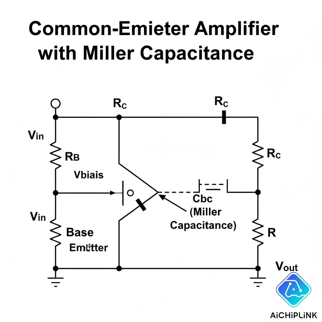
In any inverting amplifier (like a common-emitter BJT), a small parasitic capacitance exists between the input (base) and the output (collector). At high frequencies, this capacitor provides a feedback path. The result is that this small physical capacitance appears, from the input's point of view, as a much larger capacitance, effectively multiplied by the amplifier's gain.
This "Miller capacitance" forms a low-pass filter with the input source impedance, which kills the amplifier's gain at high frequencies. This is the primary reason single-stage amplifiers have poor high-frequency performance.
2.2 How the Cascode Configuration Neutralizes the Miller Effect
The cascode circuit cleverly defeats the Miller effect.
- The first stage (the common-emitter transistor, Q1) amplifies the input signal.
- Crucially, the voltage gain of this first stage is kept very low (close to 1). Why? Because its output is connected to the very low input impedance of the second stage (the common-base transistor, Q2).
- Since the Miller effect multiplies the parasitic capacitance by the stage's voltage gain, and the gain of Q1 is near unity, the Miller effect becomes negligible.
- The second stage (Q2) is a common-base configuration, which has inherently excellent high-frequency response and provides the overall voltage gain for the circuit.
It effectively isolates the high-gain output from the input, breaking the feedback path that causes the Miller effect.
3.0 How the Cascode Amplifier Circuit Works
Let's look at the classic BJT configuration. A similar principle applies to FETs (Common-Source feeding a Common-Gate).
3.1 The BJT Cascode: A Common-Emitter Feeding a Common-Base
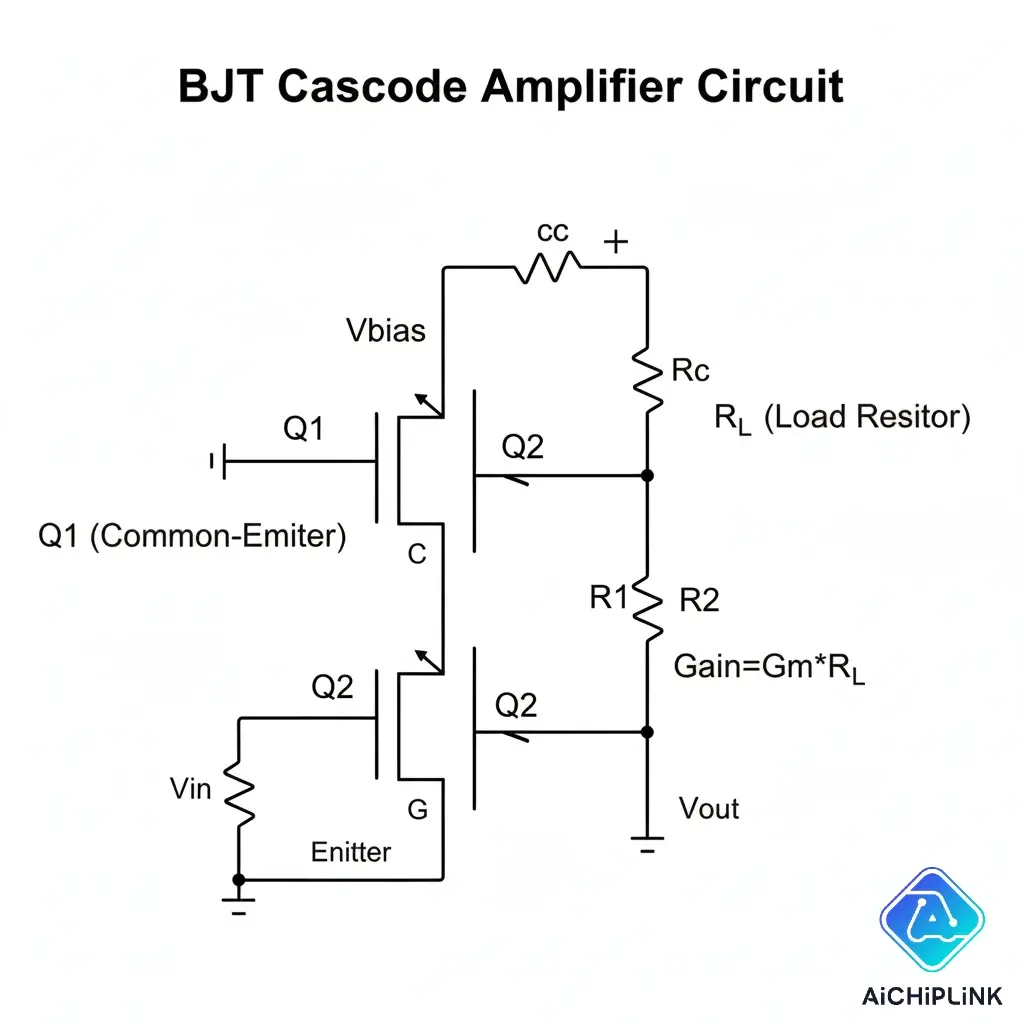
In this circuit, Q1 acts as the input transconductance amplifier, converting the input voltage to a current. Q2 acts as a current buffer, passing that current to the output load resistor while providing high output impedance and isolation.
3.2 Key Advantages of the Cascode Configuration
- Greatly Increased Bandwidth: This is the primary advantage. By mitigating the Miller effect, the cascode can operate at much higher frequencies.
- High Voltage Gain: The overall gain is comparable to a single common-emitter stage.
- High Output Impedance: Useful for driving high-impedance loads or acting as an active load itself.
- Improved Stability: The reverse isolation is much better, meaning the output is less likely to affect the input.
3.3 Disadvantages and Design Considerations
- Higher Voltage Requirement: The two transistors are "stacked," so the cascode requires a higher supply voltage to keep both transistors properly biased and out of saturation.
- Increased Complexity: It requires two transistors and more complex biasing compared to a single-stage amplifier.
"The cascode topology is a fundamental technique in RFIC (Radio Frequency Integrated Circuit) design. Its ability to provide high gain and isolation at high frequencies is essential for modern wireless communication systems." - A concept central to RF electronics, as explored in textbooks like Design of Analog CMOS Integrated Circuits by Behzad Razavi.
4.0 Practical Applications and Variations
You'll find the cascode principle used in any application where high-frequency amplification is key.
4.1 Common Cascode Amplifier Applications
- RF Tuners: As tuned amplifiers in radio and television receivers.
- Video Amplifiers: For amplifying high-frequency video signals.
- High-Frequency Oscillators: As the gain element in oscillator circuits.
- Modulators: In amplitude modulation (AM) transmitters.
- The cascode is a key building block, and you'll need quality high-frequency transistors to build effective circuits.
4.2 A Note on the Folded Cascode Amplifier
A popular variation in integrated circuits is the folded cascode. This clever topology uses a complementary transistor type (e.g., a PNP for the second stage if the first is an NPN), which "folds" the signal path. Its main advantage is that it doesn't require the high supply voltage of a standard stacked cascode, making it ideal for low-voltage IC design.
The cascode amplifier is a powerful example of clever circuit design. By combining two different transistor configurations, it creates a composite amplifier that inherits the best qualities of both: the high input impedance of the common-emitter stage and the superior high-frequency performance of the common-base stage. It stands as a testament to the engineering ingenuity required to overcome the physical limitations of components and push the boundaries of speed and performance in the world of electronics.
Looking for the right components for your next RF project? Find a wide selection of high-frequency transistors and RF components at aichiplink.com today!

Written by Jack Elliott from AIChipLink.
AIChipLink, one of the fastest-growing global independent electronic components distributors in the world, offers millions of products from thousands of manufacturers, and many of our in-stock parts is available to ship same day.
We mainly source and distribute integrated circuit (IC) products of brands such as Broadcom, Microchip, Texas Instruments, Infineon, NXP, Analog Devices, Qualcomm, Intel, etc., which are widely used in communication & network, telecom, industrial control, new energy and automotive electronics.
Empowered by AI, Linked to the Future. Get started on AIChipLink.com and submit your RFQ online today!
Frequently Asked Questions
What is the main advantage of a cascode amplifier?
The main advantage is its significantly improved high-frequency performance and bandwidth compared to a single-stage amplifier. It achieves this by mitigating the Miller effect.
What is the difference between a cascode and a cascade amplifier?
A cascade amplifier is a series of stages connected output-to-input to achieve very high gain (e.g., CE -> CE). A cascode amplifier is a specific two-transistor configuration (e.g., CE -> CB) designed for high bandwidth, not necessarily higher gain than a single stage.
What is the Miller effect?
The Miller effect is a phenomenon where the parasitic capacitance between the input and output of an inverting amplifier appears to be much larger from the input's perspective, severely limiting the amplifier's high-frequency gain.
What is the voltage gain of a cascode amplifier?
The voltage gain of a cascode amplifier is approximately the same as that of a single common-emitter or common-source stage. Its primary benefit is not increased gain, but the ability to maintain that gain at much higher frequencies.
Does a cascode amplifier have high input impedance?
Yes. The input is applied to the base of the common-emitter stage, which has a relatively high input impedance. This is one of the key advantages it combines from the common-emitter configuration.