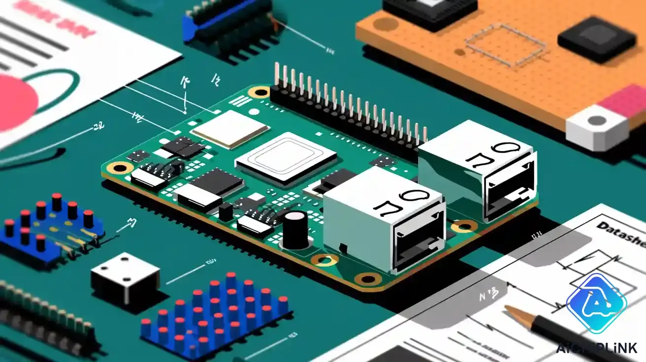
When you use the raspberry pi 2 pinout, you first look at the 40-pin GPIO header. This header is on the pi model 2. It has the same layout as newer boards like Raspberry Pi 3 and 4. You can use the same accessories and cables for these models. The pinout does not change. If you know what each pin does, you can connect devices safely. This helps you make projects that work well. A clear diagram or table of the raspberry pi 2 pinout helps you not make mistakes. It also makes your hardware projects easier.
Key Takeaways
-
The Raspberry Pi 2 has a 40-pin GPIO header. It shares this with newer models. This lets you use the same accessories. It also makes projects easier to build.
-
Always look at the pinout diagram before you connect devices. This helps you avoid mistakes. It also keeps your board safe from damage.
-
Use the right pin numbering system. Use physical pins for wiring. Use GPIO numbers for coding. This helps your projects work the right way.
-
Power pins give 3.3V and 5V. Ground pins finish circuits. Never put more than 3.3V on GPIO pins. This keeps your board from getting damaged.
-
You can control many devices with GPIO pins. They work for digital input and output. They also work for UART, I2C, SPI, and PWM. This lets you make many kinds of projects.
Raspberry Pi 2 Pinout Overview
40-Pin Header
When you look at the raspberry pi 2 pinout, you see a 40-pin header on the board. This header gives you access to many features for your projects. The pins sit in two rows, making it easy to connect wires and devices. You find power pins, ground pins, and GPIO pins mixed throughout the header. Each pin has a special job. Some give power, some connect to sensors, and others let you send signals.
Here is a table that shows the raspberry pi 2 pinout for the 40-pin header. You can use this table to find the right pin numbers for your project:
| Pin Number | Pin Name | Function / Description |
|---|---|---|
| 1 | 3.3V | 3.3V Power Rail |
| 2 | 5V | 5V Power Rail |
| 3 | GPIO2 | I2C SDA |
| 4 | 5V | 5V Power Rail |
| 5 | GPIO3 | I2C SCL |
| 6 | GND | Ground |
| 7 | GPIO4 | GPCLK0 |
| 8 | GPIO14 | UART TXD0 |
| 9 | GND | Ground |
| 10 | GPIO15 | UART RXD0 |
| 11 | GPIO17 | General Purpose I/O |
| 12 | GPIO18 | PCM CLK (I2S) |
| 13 | GPIO27 | General Purpose I/O |
| 14 | GND | Ground |
| 15 | GPIO22 | General Purpose I/O |
| 16 | GPIO23 | General Purpose I/O |
| 17 | 3.3V | 3.3V Power Rail |
| 18 | GPIO24 | General Purpose I/O |
| 19 | GPIO10 | SPI MOSI |
| 20 | GND | Ground |
| 21 | GPIO9 | SPI MISO |
| 22 | GPIO25 | General Purpose I/O |
| 23 | GPIO11 | SPI CLK |
| 24 | GPIO8 | SPI CE0 |
| 25 | GND | Ground |
| 26 | GPIO7 | SPI CE1 |
| 27 | GPIO0 | I2C EEPROM |
| 28 | GPIO1 | I2C EEPROM |
| 29 | GPIO5 | General Purpose I/O |
| 30 | GND | Ground |
| 31 | GPIO6 | General Purpose I/O |
| 32 | GPIO12 | PWM0 |
| 33 | GPIO13 | PWM1 |
| 34 | GND | Ground |
| 35 | GPIO19 | PCM FS (I2S) |
| 36 | GPIO16 | General Purpose I/O |
| 37 | GPIO26 | General Purpose I/O |
| 38 | GPIO20 | PCM DIN (I2S) |
| 39 | GND | Ground |
| 40 | GPIO21 | PCM DOUT (I2S) |
Tip: Always check the raspberry pi 2 pinout table before you connect anything. This helps you avoid mistakes and keeps your board safe.
You can use the same raspberry pi pinout for many models. The 40-pin header layout matches these boards:
-
Raspberry Pi Model A+
-
Raspberry Pi 2
-
Raspberry Pi 3
-
Raspberry Pi 4
-
Raspberry Pi Zero
-
Raspberry Pi Zero W
-
Raspberry Pi 3 Model A+
-
Raspberry Pi Model B+
If you learn the raspberry pi 2 pinout, you can use your skills with other boards. This makes your projects easier and saves you time.
Pin Numbering
You need to know how pin numbers work on the raspberry pi 2 pinout. The board uses two ways to number pins. The first way is physical pin numbers. These numbers show where each pin sits on the header. The second way is GPIO numbers. These numbers match the Broadcom chip inside the raspberry pi.
When you build a project, you must use the right pin numbers. If you mix up physical and GPIO numbers, your code may not work. You might connect a wire to the wrong pin and damage your board. For example, physical pin 8 is GPIO14. If you want to use UART, you must use GPIO14, but you connect your wire to pin 8.
The raspberry pi 2 pinout has power pins at physical pins 1, 2, 4, and 17. Ground pins sit at pins 6, 9, 14, 20, 25, 30, 34, and 39. GPIO pins fill the rest of the header. Some GPIO pins also support special features like I2C, SPI, UART, and PWM. You need to check the pinout before you start wiring.
Understanding the pin numbering system helps you use the raspberry pi pinout for coding and hardware. You can find the right pins for power, ground, and signals. This keeps your circuits safe and lets your projects work well.
GPIO Pinout Specs
Power Pins
You find power pins on the raspberry pi 2 pinout at specific locations. These pins give your devices the energy they need. The main power pins on the gpio pinout are 3.3V and 5V. You use these pins to power sensors, displays, and other small devices. The table below shows the voltage and current details for the power pins:
| Specification | Details |
|---|---|
| Voltage | 5V (regulated supply required) |
| Current (recommended) | Approximately 2.5A |
| Power Pin (GPIO header) | Pin 2 (5V) |
| Ground Pin (GPIO header) | Pin 6 (GND) |
| Important Note | No onboard regulation or fuse protection on GPIO pins; use a quality regulated 5V power source to avoid damage. |
You should always use a good power supply. This keeps your raspberry pi gpios safe and helps your projects run smoothly.
Ground Pins
Ground pins complete the circuit for your devices. You find ground pins spread across the gpio pinout. These pins help prevent electrical problems. On the raspberry pi 2 pinout, ground pins sit at pins 6, 9, 14, 20, 25, 30, 34, and 39. You connect your device’s ground wire to these pins. This makes sure your gpio pins work as expected.
Tip: Always connect your device’s ground to a ground pin on the raspberry pi gpio header. This helps avoid short circuits and keeps your board safe.
Logic Levels
The raspberry pi gpios use a 3.3V logic level. You must never apply more than 3.3V to any gpio pin. If you use higher voltages, you risk damaging your board. Even a small mistake can cause latch-up or destroy the chip. If you want to connect devices that use 5V or 12V, you need level shifters or transistors. You can also use resistors and diodes to protect your gpio pins. Always check the pinout before connecting anything new.
Current Limits
You need to know how much current your gpio pins can handle. Each gpio pin can safely supply about 16 to 18 mA. The total current for all raspberry pi gpios should not go over 50 mA. If you use more current, you can damage your board. You should use resistors with LEDs and buttons to limit current. Never connect motors or large loads directly to gpio pins.
-
Do not apply voltages higher than 3.3V to any gpio pin.
-
Avoid connecting the 5V line directly to gpio pins.
-
Do not hot-plug wires while the raspberry pi is powered on.
-
Protect against static and voltage spikes.
-
Use an analog-to-digital converter for analog sensors.
-
Power your raspberry pi through the main power connector, not the gpio pinout.
Note: Beginners should test circuits in simulation software before connecting them to the raspberry pi gpio header. This helps you learn how voltage and current work and keeps your board safe.
Raspberry Pi Pinout Functions
The raspberry pi pinout gives you many ways to use the gpio pins for different tasks. You can use them for digital i/o, serial communication, and even to control motors or lights. Each pin can have a special job, and knowing these jobs helps you build better projects.
Digital I/O
You can use most gpio pins for digital input or output. This means you can read signals from buttons or switches, or send signals to LEDs and relays. The raspberry pi gpio pins let you control many devices in your projects. Always check the pinout to see which pins are safe for digital i/o.
UART Pins
UART lets you send and receive data with other devices using serial communication. On the raspberry pi pinout, UART uses GPIO 14 (TX) and GPIO 15 (RX). These pins help you connect to modules like GPS receivers or serial displays. You can use UART for debugging or talking to other computers.
| Alternate Function | GPIO Pins (Broadcom) | Description |
|---|---|---|
| UART | GPIO 14 (TX), GPIO 15 (RX) | Serial communication pins |
I2C Pins
I2C is a way to connect sensors and chips using just two wires. The main raspberry pi i2c bus uses pins 3 (SDA) and 5 (SCL) on the header. These connect to GPIO 2 and GPIO 3. You should use these pins for most I2C devices. There is a second I2C bus on pins 27 and 28, but it is for special HAT boards and not for general use.
| Alternate Function | GPIO Pins (Broadcom) | Description |
|---|---|---|
| I2C | GPIO 2 (SDA), GPIO 3 (SCL) | I2C data and clock lines |
SPI Pins
SPI is another way to connect devices like displays or memory chips. The raspberry pi spi pins are GPIO 7 (CE1), GPIO 8 (CE0), GPIO 9 (MISO), GPIO 10 (MOSI), and GPIO 11 (CLK). You can use these pins to talk to SPI devices quickly and reliably. Always check the pinout before wiring your raspberry pi spi project.
| Alternate Function | GPIO Pins (Broadcom) | Description |
|---|---|---|
| SPI | GPIO 7 (CE1), GPIO 8 (CE0), GPIO 9 (MISO), GPIO 10 (MOSI), GPIO 11 (CLK) | SPI chip select, data, and clock lines |
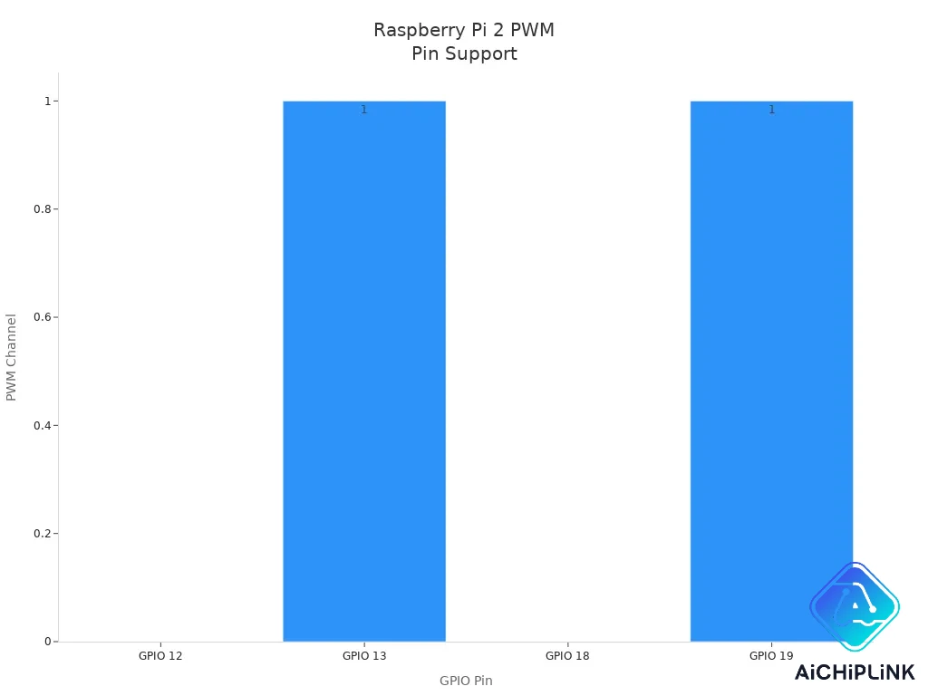
PWM Pins
PWM lets you control things like motor speed or LED brightness. The raspberry pi gpios that support PWM are GPIO 12, GPIO 13, GPIO 18, and GPIO 19. You can use these pins for hardware PWM, which gives you smooth and accurate control.
| GPIO Pin | PWM Channel | Notes |
|---|---|---|
| 12 | 0 | Available on A+, B+, Pi2, Zero, and Compute Module |
| 13 | 1 | Available on A+, B+, Pi2, Zero, and Compute Module |
| 18 | 0 | Available on all Raspberry Pi models |
| 19 | 1 | Available on A+, B+, Pi2, Zero, and Compute Module |
Tip: Use the right gpio pins for each function. This helps your raspberry pi gpio projects work well and keeps your board safe.
You can use libraries like WiringPi and Pi4J to control the gpio pins. WiringPi works with all Raspberry Pi boards and gives you fast, direct access to the hardware. Pi4J uses modern Java code and supports all the main pinout functions, including I2C, SPI, PWM, and UART. These libraries make it easier to use the raspberry pi pinout for your projects.
GPIO Pinout Datasheet
Pin Table
You need a clear overview of the 40-pin header to use the raspberry pi gpios safely. The official pinout table shows you both the physical pin numbers and the Broadcom GPIO numbers. This helps you match your wiring with your code. You can see which pins give you power, which ones are ground, and which ones work as gpio for your projects.
-
Pin 1: 3.3V Power
-
Pin 2: 5V Power
-
Pin 3: GPIO2 (SDA1, I2C)
-
Pin 4: 5V Power
-
Pin 5: GPIO3 (SCL1, I2C)
-
Pin 6: Ground
-
Pin 7: GPIO4 (GPCLK0)
-
Pin 8: GPIO14 (TXD0, UART)
-
Pin 9: Ground
-
Pin 10: GPIO15 (RXD0, UART)
-
Pin 11: GPIO17
-
Pin 12: GPIO18 (PCM_CLK, PWM0)
-
Pin 13: GPIO27
-
Pin 14: Ground
-
Pin 15: GPIO22
-
Pin 16: GPIO23
-
Pin 17: 3.3V Power
-
Pin 18: GPIO24
-
Pin 19: GPIO10 (MOSI, SPI)
-
Pin 20: Ground
-
Pin 21: GPIO9 (MISO, SPI)
-
Pin 22: GPIO25
-
Pin 23: GPIO11 (SCLK, SPI)
-
Pin 24: GPIO8 (CE0, SPI)
-
Pin 25: Ground
-
Pin 26: GPIO7 (CE1, SPI)
-
Pin 27: ID_SD (I2C EEPROM)
-
Pin 28: ID_SC (I2C EEPROM)
-
Pin 29: GPIO5
-
Pin 30: Ground
-
Pin 31: GPIO6
-
Pin 32: GPIO12 (PWM0)
-
Pin 33: GPIO13 (PWM1)
-
Pin 34: Ground
-
Pin 35: GPIO19 (PCM_FS, PWM1)
-
Pin 36: GPIO16
-
Pin 37: GPIO26
-
Pin 38: GPIO20 (PCM_DIN)
-
Pin 39: Ground
-
Pin 40: GPIO21 (PCM_DOUT)
You can use this pinout table to check pin numbers before you connect any device. This helps you avoid mistakes and keeps your raspberry pi gpios safe.
Special Pins
Some pins on the raspberry pi 2 pinout have unique roles. The ID_SD (pin 27) and ID_SC (pin 28) pins let your Raspberry Pi talk to a special memory chip on HAT boards. This feature helps your board recognize and set up new hardware automatically. You should not use these pins for regular gpio tasks. The SPI chip enable pins, CE0 (pin 24) and CE1 (pin 26), help you select which SPI device you want to talk to. These special pins make your projects more flexible and help you use advanced features.
Always check the pinout and pin numbers before using special pins. This keeps your raspberry pi gpios working well and protects your board.
Raspberry Pi Pinout Guide
Connecting Peripherals
You can connect many devices to the Raspberry Pi GPIO header. The raspberry pi pinout guide helps you choose the right pins for each task. You can use LEDs, buttons, and sensors in your projects. Here are common ways to connect peripherals:
-
Use jumper wires for quick connections.
-
Solder wires for a permanent setup.
-
Try a protoboard or breadboard for organized wiring.
When you connect an LED, always use a resistor. A 220-ohm resistor protects the gpio pin from too much current. Connect the long leg of the LED to a gpio pin and the short leg to ground. For buttons, connect one side to a gpio pin and the other to ground. You can use the 3.3V or 5V power pins for sensors.
Always power off your Raspberry Pi before connecting or disconnecting anything. Double-check your wiring to avoid mistakes.
Here are steps to follow:
-
Check the raspberry pi pinout guide for the correct gpio and ground pins.
-
Use a breadboard to keep wires neat and prevent shorts.
-
Add resistors to LEDs and buttons.
-
Make sure you use the right voltage. The gpio pins work at 3.3V.
-
Test your circuit with a multimeter before turning on the Raspberry Pi.
If you want to connect a sensor like the DHT22, wire VCC to 3.3V, GND to ground, and the data pin to a gpio pin. Add a 10k-ohm pull-up resistor between the data pin and 3.3V. You can use Python to read sensor data:
import Adafruit_DHT
sensor = Adafruit_DHT.DHT22
pin = 4  # GPIO pin
humidity, temperature = Adafruit_DHT.read_retry(sensor, pin)
print(f'Temperature: {temperature}C Humidity: {humidity}%')
Common mistakes include using the wrong pin numbers, forgetting resistors, or connecting 5V devices directly to gpio pins. Always check the raspberry pi pinout guide before you start.
Using I2C Devices
You can use the raspberry pi i2c pins to connect sensors and displays. The main I2C pins are physical pins 3 (SDA) and 5 (SCL). Here is how you set up I2C devices:
-
Enable I2C support. Run
sudo raspi-config, go to Interfacing Options, and turn on I2C. -
Reboot your Raspberry Pi.
-
Install I2C tools with
sudo apt-get install -y python3-smbusandsudo apt-get install -y i2c-tools. -
Connect your I2C device to the correct pins. SDA goes to pin 3, SCL goes to pin 5, and GND to ground.
-
Test the connection with
sudo i2cdetect -y 1. You should see your device address.
Use level shifters if your I2C device needs 5V. The gpio pins only support 3.3V.
If you do not see your device, check the wiring and make sure you enabled I2C. Use the raspberry pi pinout guide to find the right pins. Avoid long wires, which can cause signal problems.
Using SPI Devices
SPI devices use several gpio pins for fast data transfer. The raspberry pi pinout guide shows you the spi pins: MOSI, MISO, SCLK, and CS. Here is how you connect and use SPI devices:
-
Enable SPI by running
sudo raspi-configand turning on SPI in Interfacing Options. -
Find the spi pins on the pinout. MOSI is pin 19, MISO is pin 21, SCLK is pin 23, and CS is pin 24 or 26.
-
Wire your SPI device to the correct pins. Connect ground and power as needed.
-
Install SPI tools like flashrom with
sudo apt install flashrom. -
Test your setup with a logic analyzer if you have one. Look for signals on the spi pins.
| Signal | Raspberry Pi Pin |
|---|---|
| CS | Pin 24 |
| MISO | Pin 21 |
| SCLK | Pin 23 |
| MOSI | Pin 19 |
| Ground | Pin 39 |
Double-check all connections. Use short wires for best results. If you see errors, check ground and power lines.
You can use the raspberry pi spi pins for displays, memory chips, and sensors. Always use the raspberry pi pinout guide to match the pins.
UART Communication
UART lets you send and receive data with other devices. The main UART pins are GPIO 14 (TXD, pin 8) and GPIO 15 (RXD, pin 10). Here is how you set up UART communication:
-
Wire TXD (pin 8) to the RX pin on your USB-UART converter. Wire RXD (pin 10) to the TX pin. Connect ground to ground.
-
Make sure your converter uses 3.3V logic.
-
Enable the serial port using
sudo raspi-configor by editingcmdline.txt. -
Test the connection with
screen /dev/ttyUSB0 115200on your computer. -
If you want to use UART for networking, install PPP daemon with
sudo apt-get install ppp. -
Disable the serial console if you need exclusive UART access.
-
Start PPP on both devices to create a network link.
Always check the raspberry pi pinout guide for correct pin numbers. Use crossover wiring for TX and RX.
If you cannot see data, check your wiring and logic levels. Make sure you do not connect 5V devices to gpio pins.
PWM Output
PWM lets you control brightness or motor speed. You can use hardware PWM on pins like GPIO 12 (pin 32) and GPIO 18 (pin 12). Here is how you create PWM output:
-
Wire an LED to a PWM-capable gpio pin with a resistor.
-
Use Python and the gpiozero library. Import PWMLED and create an object for your pin.
-
Set the brightness by changing
led.valuefrom 0 to 1. -
Use loops to fade the LED in and out.
-
Add exception handling to turn off the LED safely.
from gpiozero import PWMLED
from time import sleep

led = PWMLED(18)  # GPIO 18, pin 12
while True:
    for value in range(0, 101):
        led.value = value / 100
        sleep(0.02)
You can also use C and the wiringPi library for more control. Set the pin mode to PWM, adjust the clock and range, and write values to change the duty cycle.
| Step | Description |
|---|---|
| 1 | Set pin mode to PWM output. |
| 2 | Adjust PWM clock divisor. |
| 3 | Select PWM mode. |
| 4 | Set PWM range. |
| 5 | Write duty cycle value. |
Use the raspberry pi pinout guide to find PWM pins. Always use resistors with LEDs. Test your circuit before running code.
Common mistakes include using non-PWM pins, skipping resistors, or using the wrong pin numbers. Always check the pinout before wiring.
GPIO Project Ideas
You can use the Raspberry Pi 2 pinout to create many fun and useful projects. These ideas help you learn how to control devices and sensors with gpio pins. Here are some beginner and intermediate projects you can try.
Blinking LED
A blinking LED is a classic starter project. You only need a Raspberry Pi, an LED, a resistor (100Ω–330Ω), a breadboard, and jumper wires. First, connect the LED’s long leg to a gpio pin (for example, GPIO 4) through the resistor. Connect the short leg to a ground pin. Make sure you check the pinout for the correct positions. After wiring, use Python to control the LED. The following code makes the LED blink every second:
import RPi.GPIO as GPIO
from time import sleep

pinLED = 4
GPIO.setmode(GPIO.BCM)
GPIO.setup(pinLED, GPIO.OUT)

while True:
    GPIO.output(pinLED, GPIO.HIGH)
    sleep(1)
    GPIO.output(pinLED, GPIO.LOW)
    sleep(1)
Always use a resistor to protect your LED and gpio pins.
Temperature Sensor
You can measure temperature using a sensor like the DS18B20 or an I2C sensor. For the DS18B20, connect the data wire to GPIO 4, VCC to 3.3V, and ground to a ground pin. Enable the 1-Wire protocol in your Raspberry Pi settings. For I2C sensors, connect SDA and SCL to the correct pins as shown in the pinout. Use Python libraries to read and display the temperature.
OLED Display
An OLED display lets you show text or data from your Raspberry Pi. Connect VCC to 3.3V, GND to ground, SDA to GPIO 2, and SCL to GPIO 3. Install the required Python libraries, such as adafruit-circuitpython-ssd1306. Write a script to display messages or sensor readings. Always check the pinout before wiring.
Home Automation
You can control lights, fans, or other devices using relay modules and gpio pins. Connect the relay’s input pins to gpio pins (for example, GPIO 17 or GPIO 27). Use Python to turn devices on or off. You can even build a web interface with Flask to control your home from a browser. Add sensors like PIR or DHT22 for automation triggers.
Resource Links
-
RaspberryTips.com: Guides and pinout diagrams
-
Official Raspberry Pi Forums: Community support
-
Reddit: r/raspberrypi and r/AskElectronics
-
Hackster.io and Instructables: Project tutorials
-
Adafruit and WiringPi: Advanced gpio libraries
-
YouTube: The Raspberry Pi Guy, Adafruit Industries
These resources help you learn more about gpio projects and the Raspberry Pi 2 pinout.
When you know the raspberry pi pinout, you feel more sure. This helps you make safe and working hardware projects. You can try new things with GPIO pins if you follow the guide. As you learn, you can try harder projects. Join online groups to show your work and ask for help. Other makers will give you ideas and support.
FAQ
What happens if you connect a 5V device to a GPIO pin?
You risk damaging your Raspberry Pi. The GPIO pins only support 3.3V logic. Always use a level shifter or voltage divider when you connect 5V devices.
How do you know which pin number to use in your code?
You can use either the physical pin number or the Broadcom GPIO number. Most libraries let you choose. Always check your code and the pinout diagram to match the correct numbering system.
Can you use multiple I2C devices on the same pins?
Yes, you can connect several I2C devices to the same SDA and SCL pins. Each device must have a unique address. Use the i2cdetect tool to check connected devices.
Why does your LED not light up when connected to a GPIO pin?
-
You may have used the wrong pin number.
-
The LED might be backward.
-
You may have forgotten the resistor.
-
The code may not set the pin as output.
Double-check your wiring and code before trying again.
Is it safe to hot-plug wires on the GPIO header?
No, you should never connect or disconnect wires while your Raspberry Pi is powered on. You could short pins or damage the board. Always power off before making changes.

Written by Jack Elliott from AIChipLink.
AIChipLink, one of the fastest-growing global independent electronic components distributors in the world, offers millions of products from thousands of manufacturers, and many of our in-stock parts is available to ship same day.
We mainly source and distribute integrated circuit (IC) products of brands such as Broadcom, Microchip, Texas Instruments, Infineon, NXP, Analog Devices, Qualcomm, Intel, etc., which are widely used in communication & network, telecom, industrial control, new energy and automotive electronics.
Empowered by AI, Linked to the Future. Get started on AIChipLink.com and submit your RFQ online today!