Comparing Metal Film and Carbon Film Resistors
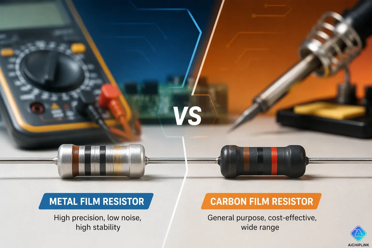
One wrong resistor can pull a circuit away from the accuracy and reliability it needs. Designers weigh many options, and two common choices stand out: Metal Film and carbon film resistors. These two types differ in precision, stability, noise, construction, and cost. A part with ±0.1% tolerance and 25 ppm/°C drift over a 60°C swing can still add about 0.25% worst-case resistance error. That gap shows why resistors deserve careful selection, and why designers compare resistors side by side. This comparison helps readers match resistors to their application needs. The right choice depends on accuracy, stability, and budget, and both types of resistors serve real roles.
Key Takeaways
-
Metal film resistors give very exact resistance and change little over time. They work well in circuits that need high precision.
-
Carbon film resistors cost less. They work well for everyday designs that need to save money.
-
Metal film resistors make less noise. They work better for audio and for signals that are easy to disturb.
-
Carbon film resistors can handle high voltage and pulses. They work well for some special uses.
-
Pick the resistor type that fits what you need. Think about accuracy, noise, and cost.
What Is a Metal Film Resistor?
Core Characteristics
A metal film resistor has a thin layer of metal alloy that acts as the resistive element. Manufacturers put that layer onto a ceramic base in a vacuum. The alloy is usually chromium and nickel, and nichrome is the most common pick. There are two ways to deposit it. Thermal deposition happens under a hard vacuum. Physical vapor deposition (PVD) uses a softer vacuum filled with argon, and sputtering within PVD is the method used most often. This process makes a dense, even layer.
Photolithography and subtractive processes then shape the metal layer. The subtractive step adjusts the resistance value, and etched patterns make the resistive path longer to set the resistance. A protective coating, base contacts, and termination sections finish the part. This order gives the component its electrical behavior and its physical strength. The finished part stands up to moisture and mechanical stress.
Precision and Stability Strengths
Tolerance is a key trait. Metal film resistors cover about ±0.1% to ±2%, and high-precision models reach ±0.1% to ±0.01%. The resistance of metal film resistors also stays steady under applied voltage. The voltage coefficient of resistance (VCR) is listed as 0.0%/V, and the value stays below 10 ppm/V, which supports better linearity at high voltage. A designer can therefore trust a stable value across the working voltage range. Designers like metal film resistors for this flat response.
Noise performance also sets the two families apart. Metal-film resistors make less thermal and excess noise than carbon film parts. Metal-film resistors also drift less with temperature, so a circuit keeps its resistance steady over time. These traits make metal-film resistors a great fit for precision circuits. An engineer who needs a tight, repeatable value will often pick a metal film resistor first. A metal film resistor also works well for low-noise signal paths. Both film resistors have a similar outer shape, yet their inner layers are different. For many precision designs, metal-film resistors give the accuracy you need at a fair price.
What Is a Carbon Film Resistor?
Core Characteristics
A carbon film resistor uses a thin layer of carbon as the part that resists current. Manufacturers put this layer on a ceramic rod using a high-heat process. The carbon forms an even coating around the core. Then a spiral groove cuts into the film to set the resistance value. This groove makes the current path longer and raises the resistance. Metal end caps and lead wires complete the assembly, and a protective jacket seals the body.
The resistance of carbon film resistors changes more from unit to unit than precision types allow. Typical tolerances run from ±2% to ±5%, with lower-cost models at only ±10%. The voltage coefficient of resistance is higher than in metal film parts, so applied voltage shifts the value more. These traits work well for general-purpose jobs, where exact values matter less. Many designers accept this spread for everyday circuits.
Cost and General-Purpose Strengths
Cost is the main reason people choose them. Carbon film resistors cost much less than metal film parts for common values. The table below shows the relative picture.
| Resistor Type | Relative Cost |
|---|---|
| Carbon film (CFR) | Low — bulk unit price roughly 1/3 to 1/5 that of metal film resistors |
| Metal film (MFR) | Higher — baseline for comparison |
This price gap makes carbon film resistors a practical choice for high-volume boards. A designer can fill many positions without going over budget. Hobbyists and students also pick them first.
One common claim needs a note. People sometimes mix up carbon comp resistors with film types, and the carbon composition and carbon film resistor myth keeps showing up in forums. The two parts use different elements and different processes. Carbon-film resistors work well for general-purpose use, and film resistors of this family remain a cost-effective standard choice.
Carbon Film vs Metal Film Resistors: Key Parameters
A side-by-side comparison of the two families starts with how each part reacts to heat and voltage. These parameters often decide which part suits a design.
Temperature and Voltage Coefficients
Heat changes resistance in both types, but the size of that change differs a lot. The temperature coefficient of resistance tells how much a part moves per degree of temperature change. Metal-film resistors hold a tight figure, while carbon film resistors have a TCR that swings far more.
| Resistor Type | Temperature Coefficient of Resistance (TCR) |
|---|---|
| Metal film | ±20 to ±200 ppm/K (also cited as 10 to 100 ppm/K) |
| Carbon film | -200 to -1000 ppm/K |
The gap matters in circuits that see wide temperature swings. A designer who needs a steady value across hot and cold conditions will find metal-film resistors outperform carbon-film resistors on this measure. The drift stays small in a metal part and grows large in a carbon part.
Voltage adds a second shift. The voltage coefficient of resistance shows how much the value moves as applied voltage rises.
| Resistor Type | Voltage Coefficient of Resistance (VCR) |
|---|---|
| Carbon Film | Poor, approximately 10–50 ppm/V |
| Metal Film | Excellent, less than 10 ppm/V |
A metal film resistors is less susceptible to this voltage shift. The differences between the metal film and carbon film resistors show up clearly here, and a head-to-head comparison favors the metal part for high-voltage accuracy. Anyone weighing a carbon film resistor vs. a metal film resistor should check this figure first. Metal-film resistors suit precision work.
Noise, Inductance, and Capacitance
Noise sets a floor on signal quality. Thermal noise comes from the random motion of charge carriers, and film morphology shapes the excess portion. Thin film parts show levels roughly 20–30% lower than thick film parts, with densities as low as 0.1 nV/√Hz at 1 kHz. Some studies report a 40–50% gap. Resistance and temperature largely set this noise, so the figures reflect film structure more than a metal-versus-carbon gap.
Excess noise separates the two types more sharply. Metal-film resistors also keep excess noise low.
| Resistor type | Current (excess) noise level |
|---|---|
| Carbon film | 0.5 – 1 μV/√Hz (higher, due to uneven carbon particles and grooving burrs) |
| Metal film | < 0.1 μV/√Hz (extremely low, due to uniform alloy layer and laser-etched smooth grooves) |
-
Carbon film: medium–high excess noise, fine for general purpose where noise is not critical
-
Metal film (axial): low excess noise, suited to precision analog, audio, and instrumentation
-
Thin film sits very low and metal foil extremely low, while carbon composition runs high
-
Exact values vary by manufacturer and series, so datasheets matter for critical designs
Parasitic inductance and capacitance stay small in both types. Spiral grooves create a slight inductive effect, and both families land around 5–50 nH. Metal-film resistors use finer grooves with more turns, so inductance runs slightly higher, yet the effect stays negligible in low and most mid-frequency use. Both types show significant high-frequency effects above 100 MHz, where the series inductance raises impedance with frequency. Parasitic capacitance is not specified in the source data for either type.
How Construction Shapes Metal Film Performance
Deposition and Trimming
Metal film resistor construction begins with a clean ceramic base. Manufacturers put a metal alloy film, like NiCr, onto that surface using vacuum deposition or sputtering. Next, they micro-pattern the deposited film. Film thickness is kept at the nanometer level, so the resistive layer is thin and even. This thin metal film gives the part its predictable electrical behavior.
Trimming then sets the final value. Abrasive trimming sends fine abrasive media, such as 0.027 mm aluminum oxide, through a carbide nozzle. The nozzle moves over the fired resistor while probe contacts check the value. The blast stops and the nozzle pulls back once the part hits its target. Laser trimming is another option, and it can run passively or actively while the circuit is powered up.
Why Precision Improves
Each construction step tightens the result. A uniform alloy layer and nanometer-level thickness control cut unit-to-unit spread, which supports tolerances as tight as ±0.1%. The same uniformity keeps the voltage coefficient of resistance below 10 ppm/V. Smooth, laser-etched grooves also limit excess noise, and the dense layer resists long-term drift.
These gains have limits. Standard metal film resistors cover mainstream precision needs well. Metal foil parts serve the highest-precision niche, such as metrology and reference circuits. Designers should match the grade to the job rather than assume every precision part performs alike.
How Construction Shapes Carbon Film Performance
Deposition and Trimming
Carbon film resistor construction begins with a ceramic rod. Manufacturers apply a carbon-graphite mix onto that rod using vacuum evaporation. The carbon creates a thin layer around the core. Then a mechanical process cuts a spiral groove into the film to set the resistance value. The groove makes the current path longer and raises the resistance to the target.
This process sets the electrical behavior of every carbon film resistor. Mechanical grooving gives limited precision, and film thickness and density can vary from part to part. These process traits explain the wider tolerances of carbon film resistors, which range from ±2% to ±5%, with lower-cost models at only ±10%. The same traits raise the voltage coefficient of resistance, so the value shifts more as applied voltage goes up. A carbon film resistor also drifts over time, usually about ±5% over 1000 hours, because the porous film takes in moisture. Batch-to-batch consistency stays poor, even from one manufacturer.
Why Cost Stays Low
The deposition and grooving steps keep production simple and fast. Vacuum evaporation coats many rods at once, and mechanical grooving needs no costly laser system. Simple ceramic cores and standard end caps keep material costs down. These choices support the low price of carbon-film resistors without hurting their role.
Designers accept the wider spread because general-purpose circuits can handle it. A carbon film resistor fits bulk boards, hobby builds, and everyday signal paths. Buyers who need tighter values can sort parts or move up to another family. The process keeps carbon-film resistors affordable, and that price keeps them in wide use. Many film resistors of this family still fill positions where exact values matter less than cost.
Availability, Tolerances, and Power Ratings
Resistance Ranges and Tolerances
Both families cover a wide range of resistance values, so most designs can find a match in either type. The real difference is how tightly each part holds its value. The table below shows the standard tolerance options for each family.
| Resistor Type | Standard Tolerance Options |
|---|---|
| Carbon Film | ±2% to ±5% (lower-cost models at ±10%) |
| Metal Film | ±1% typical; high-precision models ±0.1% to ±0.01% |
A carbon film resistor works for circuits that can accept a broad spread. A metal film part gives the tight tolerance that precision work needs. Buyers who need a narrow window should check the datasheet before ordering. The tolerance figure on the label tells only part of the story, and drift over time adds to the real error.
Availability does not favor either type. Distributors stock common values in both families, and lead times stay short for standard parts. A designer can source a carbon film resistor in bulk without trouble. Metal film parts also ship in volume, though the tightest grades cost more and may need a longer order cycle.
Power Ratings and Packages
Power handling follows a similar pattern. Metal film resistors come in common ratings of 0.125 W, 0.25 W, 0.5 W, and 1 W, with higher specialized options available. Standard metal film parts also span 0.25 W to 5 W, and the rating appears on the packaging or the specification sheet. Package formats include axial through-hole, surface mount chip, leadless, and MELF.
Carbon film parts follow the same through-hole tradition. A typical carbon film resistor rated at 220 Ω carries a 1/4 W rating, with axial 0.4 W parts as compatible substitutes. Tolerance for that part runs ±10%, and ±5% to ±10% substitutes are permitted. Through-hole axial remains the standard format, and surface-mount 0805 serves as an alternate.
Package choice often follows the assembly method. Through-hole parts suit breadboards and hand-soldered boards. Surface-mount formats fit automated lines and dense layouts. Designers should match the power rating to the expected dissipation and leave margin for heat.
Carbon Film Resistor vs Metal Film: Cost and Fit
Cost Comparison
Price is the first thing that separates the two families. A carbon film resistor costs about one-third to one-fifth as much as a metal film part of the same value. That gap makes carbon film the better pick for mass production, where a board may hold dozens of resistors. A buyer who fills a high-volume run with carbon-film resistors cuts the resistor cost sharply.
The metal film part costs more up front. That extra money buys tighter tolerance, lower noise, and steadier behavior over temperature. So the carbon film resistor vs metal film debate is about value, not just price. A designer should ask what the extra spend gives back in the finished product.
A long service life changes the math. Metal-film resistors drift less when stressed by the environment and by aging. Their reliability and longer lifespan often make up for the higher purchase price by cutting maintenance and replacement costs. The economic edge of metal film grows strongest in instrumentation and audio gear, where steady performance over time drives success. Any carbon film resistor vs metal film cost review should weigh the full life of the product, not the unit price alone.
Matching Type to Application
What the application needs decides the fit. Metal-film resistors earn their extra cost in circuits where error and noise hurt performance. The table below maps common cases.
| Application Area | Why Metal Film Resistors Are Cost-Effective Despite Higher Unit Cost |
|---|---|
| High-precision analog front ends, ADC/DAC inputs, amplifier bias circuits, timing-sensitive modules | Lower noise, more stable temperature coefficients, and tighter resistance tolerances deliver performance that cheaper resistors cannot match. |
| Precision measurement (op-amp feedback, precision references, bridge/strain-gauge circuits) | Tight tolerance (±0.1%–±1%) and low TCR keep gain and reference errors small over wide temperature ranges, avoiding costly calibration and rework. |
| Audio signal paths (headphone amplifier dividers, high-fidelity audio, tube amps) | Low noise (<0.1 µV/√Hz) prevents distortion and preserves signal purity. |
| Medical instruments (blood pressure monitor sensor amplification) | ±0.5% tolerance and low noise keep measurement error within ±1 mmHg. |
| Industrial control and long-lifetime instrumentation | Superior reliability and stability reduce maintenance and replacement costs over prolonged operation. |
The carbon film resistor vs metal film choice flips for cost-sensitive work. General electronics and appliances need basic function and low cost, with no strict accuracy or noise demands. Carbon-film resistors shine here. Typical jobs include voltage dividers in power circuits, current limiting for LED drivers and relay coils, and control boards in washing machines and air conditioners. A ±10% part meets these needs at a fraction of the price.
Other niches favor carbon film too. Some designs handle voltages up to roughly 15 kV, and certain variants run to about 350°C. Pulse-rich settings suit their surge tolerance. Vintage audio builders pick them for a warmer, softer tone with a subtle distortion some listeners want. A carbon film resistor vs metal film pick should follow the job, and both parts keep a place. For the highest precision, metal foil serves metrology and reference circuits. Each carbon film resistor vs metal film decision, each carbon film resistor vs metal film trade-off, and each carbon film resistor vs metal film review rewards a clear look at the application first.
Drawbacks of Each Type
Metal Film Limitations
The biggest problem with a metal film resistor is its price. When you buy in bulk, a carbon film part with the same specs costs about one-third to one-fifth as much. That difference adds up quickly on a board with dozens of spots to fill. A designer who puts metal film in every slot pays for precision that many paths never need.
Simple circuits show where the extra money goes to waste. Voltage dividers in power circuits, LED indicator drivers, small relay coil current limiting, and appliance control boards only need basic switching or current limiting. A carbon film part with ±10% tolerance does those jobs at a fraction of the cost. Swapping in a metal film part is usually safe in most low-frequency circuits below 1 MHz, but the tighter tolerance and lower noise bring no real benefit to an indicator path or a button signal line. Metal film earns its place in precision work, not in every position.
Carbon Film Limitations
Carbon film parts give up accuracy and stability. Film uniformity and mechanical grooving limit how tightly the value holds, so the tolerance runs ±2% to ±5%, with lower-cost models at only ±10%. The temperature coefficient of resistance also swings widely, and the value moves noticeably across temperature extremes. Long-term stability suffers too. Oxidation and flaking from heat and humidity weaken layer adhesion, and the resistance can drift by more than 5% after about five years.
Noise is the other weak point. Uneven carbon particles and grooving burrs raise current noise to 0.5–1 μV/√Hz, compared with under 0.1 μV/√Hz for metal film. That level gets in the way of weak signals and audio paths. Thermal noise stays closer between the families, so excess noise drives the gap. These limits do not make carbon film a poor part. They simply mark its fit: general-purpose work where cost matters more than a tight, quiet, steady value. Carbon comp resistors share the noisy reputation, yet they remain a separate family with their own behavior.
The choice depends on the job. Metal film resistors give tolerances as tight as ±0.1%, a temperature coefficient of ±20 to ±200 ppm/K (also cited as 10 to 100 ppm/K), and current noise under 0.1 μV/√Hz. They work well for precision measurement, audio paths, medical instruments, and high-voltage circuits, where a lower voltage coefficient also helps. Carbon film parts cost only one-third to one-fifth as much in bulk. They fit consumer electronics, standard power supplies, switches, and indicator drivers.
A simple framework helps. Designers should list the accuracy, noise, and stability demands first. Tight demands point to metal film. Loose demands and a tight budget point to carbon film. Both resistor types remain valuable and widely used in modern electronics.

Written by Jack Elliott from AIChipLink.
AIChipLink, one of the fastest-growing global independent electronic components distributors in the world, offers millions of products from thousands of manufacturers, and many of our in-stock parts is available to ship same day.
We mainly source and distribute integrated circuit (IC) products of brands such as Broadcom, Microchip, Texas Instruments, Infineon, NXP, Analog Devices, Qualcomm, Intel, etc., which are widely used in communication & network, telecom, industrial control, new energy and automotive electronics.
Empowered by AI, Linked to the Future. Get started on AIChipLink and submit your RFQ online today!
Frequently Asked Questions
Which type offers tighter tolerance?
Metal film wins here. Standard parts hold ±1%, and precision grades reach ±0.1% or tighter. Carbon film parts usually fall between ±2% and ±5%, with lower-cost models at only ±10%. If a design needs a narrow window, start with metal film.
Which resistor makes less noise?
Metal film makes much less excess noise. Its current noise stays under 0.1 μV/√Hz, while carbon film runs 0.5–1 μV/√Hz. Weak signals and audio paths do better with the quieter part. General-purpose circuits hardly ever notice the difference.
When does carbon film make more sense?
Carbon film fits cost-sensitive work. In bulk, it costs about one-third to one-fifth as much as metal film. Voltage dividers, LED current limiting, and appliance control boards need basic function, not tight accuracy. Carbon film meets those needs at low cost.
Is metal film ever overkill?
Yes. An indicator path or a button signal line gains little from ±0.1% tolerance or low noise. Metal film earns its price in precision measurement, audio, and medical instruments. Simple circuits do fine with a cheaper part.
Where does metal foil fit?
Metal foil sits above standard metal film. It serves the highest-precision niche, such as metrology and reference circuits. Designers should match the grade to the job instead of assuming every precision part performs alike.