Building a Magnetic Polarity Detector Circuit using a Hall Effect Sensor
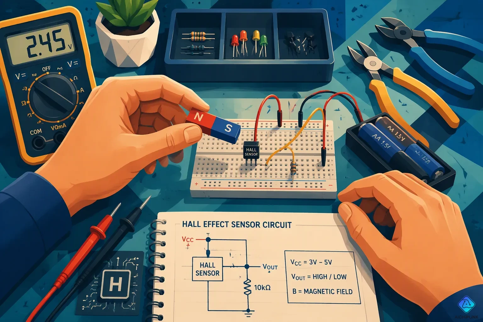
You pull a magnet from a parts bin and pause. Which face is north? Install it backward and your assembly fails. A magnetic polarity detector circuit solves that problem. This post shows you how to build one with a Hall effect sensor, step by step.
Your finished magnetic polarity detector lights an LED for each pole, so you always know what you hold. A magnetic polarity tester costs little, and a magnetic pole detector this small fits in a pocket. You can assemble this simple inexpensive diy magnetic polarity tester yourself. Treat the magnet pole tester as your first project, and let the magnetic tester hall effect sensor teach you sensor skills. Start building today.
Key Takeaways
-
A Hall effect sensor changes magnetic polarity into an electrical signal.
-
The A3144 sensor detects only south poles on its branded face.
-
To build the detector, you need a sensor, two LEDs, resistors, and a power source.
-
Connect the sensor using a pull-up resistor, then test it with a magnet to watch the LEDs change.
-
Use your detector to check magnet polarity before you put things together, or to sort parts.
How a Hall-Effect Sensor Senses Polarity
What the Sensor Outputs
A hall-effect sensor changes magnetic flux density into an electrical signal that matches it. Inside the sensor is a thin semiconductor slab. A DC supply sends a steady current through that slab. When you put a magnet perpendicular to the current, the magnetic force pushes electrons to one side. Charge builds up across the slab and makes a small voltage. Engineers call this the Hall voltage. A stronger field makes a larger voltage, so the output follows field strength directly.
The output also depends on the angle between the sensor and the field. The Hall voltage equals the field strength times the sine of that angle. Hold the magnet at a fixed distance and turn it, and the output rises and falls in a smooth wave. This behavior lets a hall effect sensor detect magnetic fields along one axis with good precision.
| Aspect of the Field | Effect on Output Voltage |
|---|---|
| Field strength | Output rises with field strength; many sensors scale with supply voltage too |
| Field direction | The sensor reads only the component along its sensing axis, which can be positive or negative |
| Full 2-D or 3-D direction | One element senses one axis; more elements are needed for full direction |
Telling North from South
The sign of the output tells you the polarity of the magnetic field. Bring the south pole of a magnet near the sensor, and the output voltage goes up above its resting value. Bring the north pole near, and the voltage drops below that value. The gap between the reading and the resting value shows the polarity of a magnet at a glance.
A Hall effect latch IC gives you one simple way to detect magnet polarity. Power the chip, and one of its two latched outputs stays low, lighting the LED on that pin. A strong enough field flips the outputs, and the other LED lights. Flip the magnet to its opposite face, and the lit LED switches between blue and red. The LED state alone lets you determine polarity, and this hall-effect sensor trick makes a clean, code-free build.
Parts for Your Magnetic Polarity Detector Circuit
Core Components and Specs
Every magnetic polarity detector circuit needs three core parts. You need a hall-effect sensor, a power source, and two indicator LEDs. The sensor does the sensing. The power source feeds it. The LEDs report which pole you hold.
The A3144 is a popular choice for this build. Its supply voltage ranges from 4.5 V to 24 V, so a 9 V battery works well. Pin 1 is VCC, pin 2 is GND, and pin 3 is the output. The output is an open-collector NPN stage rated for 25 mA of continuous sink current. That current drives an LED directly through a series resistor. The APX9141 is another suitable hall effect sensor ic for the same job.
| Parameter | Value | Notes |
|---|---|---|
| Supply voltage | 4.5–24 V | Wide range suits battery power |
| Output sink current | 25 mA max | Drives an LED directly |
| Operate point | 175 Gauss max | South pole on the branded face |
| Release point | 45 Gauss min | Hysteresis stops chatter |
| Operating temperature | -40 to +85 °C | Works in a cold shop or a hot car |
One detail matters here. The A3144 is a unipolar switch. Only a south pole on the branded front face trips it. A north pole will not operate it. Plan your two-LED design around that behavior.
Optional Add-Ons
You can salvage a hall effect sensor from an old PC fan. Peel off the sticker on the hub. Remove the stator to reach the round PCB inside. The small three-legged part on that board is your sensor. Test it before you trust it.
A resistor for each LED protects the sensor output. A small breadboard and jumper wires speed up assembly. A battery holder turns the build into a diy battery powered magnet pole tester you can carry anywhere. None of these parts cost much, and most hobbyists already own them.
Wiring a Hall Effect Magnetic Field Polarity Detector
Reading the Diagram
Start with the hall effect sensor pinout. The A3144 has three pins, and each one has a clear job.
| Pin No. | Pin Name | Function |
|---|---|---|
| 1 | +5V (Vcc) | Power supply for the sensor; typically +5V DC is applied |
| 2 | Ground | Connected to the circuit ground |
| 3 | Output | Digital output that goes high when a magnet is detected; output voltage equals the operating voltage |
Read the magnetic polarity detector schematic from left to right. Power enters pin 1. Ground returns through pin 2. The output leaves pin 3 and feeds your indicators. Add a 10k ohm pull-up resistor between pins 1 and 3. This resistor keeps the output high when no magnetic field is present. Place a 0.1 µF capacitor between pins 2 and 3 to filter noise from the digital output. The circuit diagram stays small, and you can trace every wire with one finger.
Step-by-Step Connections
Follow these steps in order. Keep the power off until the last step.
-
Seat the sensor across the breadboard's center channel. The flat face points toward you.
-
Run a jumper from pin 1 to the positive rail. Run a second jumper from pin 2 to the ground rail.
-
Fit the 10k ohm pull-up resistor between pins 1 and 3.
-
Fit the 0.1 µF capacitor between pins 2 and 3.
-
Wire LED 1 from pin 3 through its series resistor to ground. Use a red LED for the north pole.
-
Wire LED 2 from pin 3 through its own series resistor to the positive rail. Use a blue LED for the south pole.
This two-sensor design uses two different colored LEDs to show north and south poles. One LED lights for each face, so you never guess. The build acts as a hall effect magnetic field polarity detector with a visual answer.
You can also skip the LEDs and use the voltmeter method. Connect the sensor to power and clip a voltmeter between pin 3 and ground. Watch the voltage change as you bring each face near. A rise above the resting value means one pole. A drop means the other. This approach suits a quick magnet polarity detection circuit on a test bench.
Power the rails from a 5 V supply. Bring a magnet toward the branded face. Note which LED lights. Flip the magnet and note the change. Your magnetic polarity detector now works, and the hall effect sensor pinout above explains every connection you made.
Build and Test Your Simple DIY Magnetic Pole Detector
Breadboard Assembly
A simple diy magnetic pole detector comes together fast on a breadboard. Work with the power off and build in a fixed order.
-
Push the hall-effect sensor across the center channel with its flat face toward you.
-
Jumper pin 1 to the positive rail and pin 2 to the ground rail.
-
Fit the 10k ohm pull-up resistor between pins 1 and 3.
-
Fit the 0.1 µF capacitor between pins 2 and 3.
-
Wire the red LED from pin 3 through its series resistor to ground.
-
Wire the blue LED from pin 3 through its own series resistor to the positive rail.
Check every jumper against the diagram before you apply power. One misplaced wire can reverse an LED or short a rail.
Powering Up and Checking Poles
Apply 5 V to the rails. The blue LED should light with no magnet nearby, because the pull-up holds the output high. Bring the south pole toward the branded face. The output drops, the blue LED dims, and the red LED takes over. Flip the magnet, and the blue LED returns. This behavior matches the sensor's response to field orientation rather than to one specific pole, so the lit LED tracks the direction of the magnetic field relative to the sensor.
A voltmeter shows the same story in numbers. On a 5 V supply, the output rests near the midpoint at about 2.5 V. A south pole pushes the reading up toward 5.0 V. A north pole pulls it down toward 0 V. This ratiometric swing gives you a clear polarity reading at any distance.
You can also build a code-based version with an Arduino and an A3144. Wire VCC to the 5 V rail, GND to ground, and the output to digital pin D2. Set D2 as an input, open the Serial Monitor at 9600 baud, and print the digital state. Move a magnet near the sensor and watch the value flip. This path suits anyone who wants a magnet polarity detector with a screen readout instead of LEDs.
Test both faces several times. Confirm the LEDs swap cleanly and the voltmeter moves in the right direction. Your magnet pole tester is now ready for real work.
Applications and Upgrades
Everyday Uses
A magnetic polarity tester is a handy tool for any workbench. Check the polarity before you mount a magnet, and you avoid putting it in backward. Sort a mixed bin of parts by pole, and assembly gets faster. The same tool helps you inspect hardware you already own.
-
Move the sensor along a ring-shaped magnet from a brushless fan. The polarity flips every 90 degrees, which matches the four stator coils spaced 90 degrees apart. You can see how the spinning magnetic field drives the rotor.
-
Turn a cylinder-shaped magnet from a small brushless motor past the sensor. The poles switch as it spins. Run the same check on a larger cylinder-shaped rotor.
-
Test magnets with complex or unusual shapes. The device reads their poles reliably when other methods fail.
-
Take the idea further with a smartphone magnetometer. That experiment finds hidden magnets and reports their polarity.
Ideas to Extend the Build
You can make magnet polarity detection more flexible with a few small changes. Add jumper straps that feed two gates, and you choose which field direction triggers detection. You no longer have to flip the magnet by hand. Fit a potentiometer as the comparator reference, and you set the switching threshold yourself. A resistor across the comparator adds hysteresis, so the output switches cleanly instead of chattering.
A delay stage gives you timing control. When the field passes the threshold, a capacitor discharges and then recharges through a resistor, producing a delay of roughly T = 0.7 × R4 × C1. A second network blocks relay activation at power-up. You can also move the hall effect sensor 10–20 cm from the board for cramped spaces. Swap the gate IC for a CD4011 if you like; the time constants shift slightly but stay workable. Protection diodes guard against reversed supply voltage and relay coil kickback. Each upgrade keeps the hall effect sensor at the heart of the circuit.
You now have a complete path from start to finish. Follow these key steps:
-
Identify the sensor pinout from the datasheet.
-
Gather the A3144 sensor, LED, 7805 regulator, 0.1µF capacitor, 10k resistor, jumper wires, and breadboard.
-
Build the power stage and wire the sensor.
-
Bring a magnet near and watch the LED or voltage output.
This magnetic polarity detector circuit suits any beginner. The build is simple, and every part is easy to find. Your magnetic polarity detector works on the first try when you check each connection.
Use your magnetic pole detector to sort parts or check magnets before mounting. Add an Arduino readout or a buzzer later. Your pole detector is ready, so grab a magnet and start testing today.

Written by Jack Elliott from AIChipLink.
AIChipLink, one of the fastest-growing global independent electronic components distributors in the world, offers millions of products from thousands of manufacturers, and many of our in-stock parts is available to ship same day.
We mainly source and distribute integrated circuit (IC) products of brands such as Broadcom, Microchip, Texas Instruments, Infineon, NXP, Analog Devices, Qualcomm, Intel, etc., which are widely used in communication & network, telecom, industrial control, new energy and automotive electronics.
Empowered by AI, Linked to the Future. Get started on AIChipLink and submit your RFQ online today!
Frequently Asked Questions
Which Hall effect sensor should I pick for this build?
The A3144 works well for most beginners. It accepts 4.5 V to 24 V, so a 9 V battery or a 5 V rail both suit it. The APX9141 is a fine alternative. Check the datasheet pinout before you wire either part, because pin order can differ between models.
Why does only one magnet face trigger my A3144?
The A3144 is a unipolar switch. Only a south pole on the branded face reaches its operate point of 175 Gauss. A north pole will not trip it. Plan your LED wiring around that behavior, or choose a latch IC if you want both faces to switch the output.
Do I really need a resistor in series with each LED?
Yes. The sensor output sinks up to 25 mA, and an LED without a series resistor can draw too much current and fail. The resistor limits that current and protects both the LED and the sensor. Pick the value from your LED's forward current rating.
Can I trust a sensor pulled from an old PC fan?
Often yes, but test it first. Wire it to power and watch the output with a voltmeter as you bring a magnet near. A working part will change its output voltage. A dead or damaged part will not respond, and you should replace it.
My circuit shows no response. Where should I look first?
Check the pull-up resistor between pins 1 and 3. Without it, the open-collector output floats and the LEDs behave unpredictably. Then confirm pin 1 has power and pin 2 has ground. A reversed supply connection is the next most common mistake.