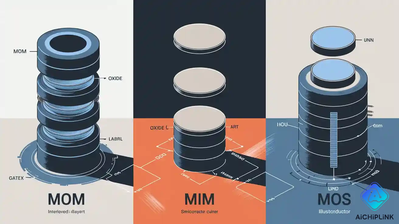
You often see the difference between mom, MIM, and MOS capacitors when you work with integrated circuits. Each type of capacitor is good for different jobs in integrated circuits. MOM capacitors use normal metal layers, so they are easy to make. MIM capacitors need more steps to make, but they are more accurate. MOS capacitors have the highest capacitance density, but their performance changes when the voltage changes. The table below shows how capacitance density, how hard they are to make, and what they are used for compare:
| Property | MOM | MIM | MOS |
|---|---|---|---|
| Capacitance density | High | Moderate to high | Moderate to high |
| Manufacturing complexity | Simple | More complex | Standard process |
| Applications | Integrated circuits, microelectronics, analog and RF circuits | Integrated circuits, memory modules, analog and RF circuits | Integrated circuits, MOSFETs, sensors, analog applications |
Picking the right capacitor depends on what your design needs:
MOM capacitors are a good mix of cost and performance in integrated circuits.
MIM capacitors are best for jobs that need to be very exact.
MOS capacitors save space but are only good for certain uses.
Key Takeaways
-
MOM capacitors do not cost much and are simple to make. They work well for many uses in analog and RF circuits.
-
MIM capacitors have high capacitance density and are very precise. They are good for high-frequency and small-space uses. But, making them is harder and needs more steps.
-
MOS capacitors give the most capacitance for their size. Their values can change with voltage. They are useful in many circuits, especially for analog signal processing.
-
You should pick the right capacitor for your design needs. Think about things like capacitance, frequency, voltage rating, and how hard it is to make.
-
Always look at what your project needs before you choose MOM, MIM, or MOS capacitors. This helps you get the best results.
MOM Capacitor
Structure
A MOM capacitor has metal lines with oxide between them. The metal lines run side by side and are close together. Oxide sits in the spaces between these lines. You connect every other line to make two ends for the capacitor.
-
Many metal lines are placed next to each other
-
Oxide is found between the metal lines
-
Every other line is joined to make two terminals
This design lets you use regular metal layers in your chip. You do not need extra steps or special masks to make it.
Working Principle
A MOM capacitor holds charge between metal lines with oxide in the middle. The metal and oxide layers create both sideways and up-and-down capacitance. This setup gives you different types of capacitance.
Here is a table that shows how MOM capacitors work compared to MIM capacitors:
| Feature | MOM Capacitors | MIM Capacitors |
|---|---|---|
| Structure | Metal-oxide-metal with oxide layer | Metal-insulator-metal with high k-dielectric |
| Capacitance Characteristics | Lateral and vertical capacitance | Primarily vertical capacitance |
| Cost | Generally cheaper | Higher cost |
| Capacitance Density | Lower capacitance density | Higher capacitance density |
Advantages
MOM capacitors have many good points:
-
You use metal layers that fit together, so you get more capacitance than simple metal shapes.
-
You save money because you do not need extra masks or steps.
-
The regular metal-oxide-metal process makes it easy to make bigger chips.
-
You get good matching and less unwanted effects in most uses.
Disadvantages
There are some things to watch out for with MOM capacitors:
-
They have less capacitance density than MIM capacitors, so you need more space for the same amount.
-
The way you lay out the metal lines can make the values change, so they are less exact.
-
MOM capacitors may not work well for jobs that need very precise values.
Applications
MOM capacitors are used in many chips. They work well in analog and RF circuits. You also see them in microelectronics when you want something cheap and easy to make bigger. The metal-oxide-metal design lets you add these capacitors without changing your normal process. You pick MOM capacitors when you want simple making and good results for big designs.
MIM Capacitor
Structure
A mim capacitor has two metal plates. One plate is on the bottom. The other plate is on top. A thin dielectric layer sits between the plates. The bottom plate rests on a buffer layer. The top plate touches the dielectric layer. Another dielectric layer covers the top plate.
-
Top metal plate
-
Bottom metal plate
-
Dielectric layer between plates
-
Buffer layer under bottom plate
-
Inter-level dielectric layer above top plate
This design makes the plates very close together. It helps build a strong and steady capacitor for your chip.
Working Principle
A mim capacitor holds charge between two metal plates. The plates are very close, but the dielectric keeps them apart. You get more capacitance if the plates are bigger or closer. The dielectric material helps store more energy. If you use a high dielectric constant, you get even more capacitance. Some designs use carbon nanofibers to make the surface area larger. This lets you store more charge in a small space. Mim capacitors give you more capacitance per area than other types.
Advantages
Mim capacitors have many good points.
-
You get more capacitance per area because the plates are close and the dielectric is thin.
-
The dielectric is strong. Some mim capacitors can handle voltages up to 23.8 V or even 34.1 V. The breakdown field strength can reach 6.1 ± 0.1 MV/cm.
-
They have high energy density. You can change the dielectric thickness to fit your needs. This helps when space is tight.
-
Mim capacitors work well in high-frequency and analog circuits.
Tip: Pick mim capacitors if you need high capacitance in a small space or if your design needs to handle high voltages.
Disadvantages
There are some things to think about before you choose mim capacitors.
| Disadvantage | Description |
|---|---|
| Extra Process Steps | You need more steps to add mim capacitors, especially with copper. |
| Higher Manufacturing Costs | The cost per mm² is higher because the process is harder. |
| Size Limits | Big RF parts can make it hard to shrink the area in transceivers. |
Mim capacitors need more work and cost more to make. The extra steps can slow down how fast you build chips.
Applications
Mim capacitors are used in many places. They are good for analog and RF circuits. You find them in memory modules and chips where space is small. Mim capacitors are best when you need high accuracy and high capacitance in a tiny area. They are also used for high-voltage jobs because the dielectric is strong. The metal-insulator-metal design makes mim capacitors a great choice for advanced microelectronics.
MOS Capacitor
Structure
You see the MOS capacitor in lots of chips. Its design is simple but strong. Here is how you make a metal-oxide-semiconductor capacitor:
-
Put a metal gate on top. This gate is usually aluminum or polysilicon.
-
Add a thin oxide layer under the gate. Silicon dioxide is the most common type.
-
Use a semiconductor base. Most times, it is silicon. It can be p-type or n-type.
-
The metal gate should be thick enough for even voltage.
-
The oxide layer must block current. No current should pass through it.
-
The place where oxide meets semiconductor should have no extra charges.
-
The semiconductor needs to be evenly doped and thick enough.
-
You need ohmic contacts on the back for it to work right.
-
The design is one-dimensional. You only think about changes in one direction.
-
The metal’s work function should match the semiconductor.
This setup gives the MOS capacitor special features.
Working Principle
The MOS capacitor stores charge between the metal gate and the semiconductor. The oxide layer stops current from flowing. When you put voltage on the gate, you change the surface and the number of carriers in the semiconductor. This makes the capacitance change with the voltage. There are three main ways it works:
-
In accumulation, many carriers gather at the surface. Capacitance is high.
-
In depletion, the region gets wider. Capacitance goes down.
-
In inversion, a new layer forms at the surface. Capacitance depends on frequency.
The capacitance changes with voltage. This makes the MOS capacitor different from other types. You can adjust the capacitance by changing the gate voltage.
Advantages
MOS capacitors have many good points:
-
They give high capacitance per area, usually 2.16 to 3 F/m².
-
You get very exact values, with errors less than 5%.
-
Matching is great, with accuracy up to 0.1%.
-
MOS capacitors work with all MOS technologies.
-
You can change the capacitance by adjusting the voltage.
Tip: Pick a MOS capacitor if you want high capacitance in a small space and need to change the value with voltage.
Disadvantages
There are some limits to MOS capacitors:
| Disadvantage | Description |
|---|---|
| Voltage Dependence | Capacitance changes when you change the voltage. This can be a problem in some circuits. |
| Nonlinear Behavior | MOS capacitors do not always act like simple capacitors. |
| Frequency Sensitivity | In inversion, capacitance changes with signal frequency. |
| Leakage Current | If the oxide is too thin, current can leak. |
Think about these things before you pick a MOS capacitor for your design.
Applications
MOS capacitors are used in many modern circuits. Here are some common uses:
-
Analog signal processing
-
Filtering
-
Secure communication
-
MOS-only circuits
-
MOSFET-C circuits
MOS capacitors are popular because you can make them with regular MOS processes. You can use them in analog, digital, and mixed-signal designs. You can change the capacitance with voltage, so MOS capacitors are flexible for many jobs.
Difference Between MOM, MIM, and MOS Capacitors
Comparison Table
There are many ways MOM, MIM, and MOS capacitors are not the same. Each type has its own structure and use. They have different capacitance density and how hard they are to make. Their voltage dependence and dielectric strength are not equal. You can look at tables to see these features side by side.
| Capacitor Type | Structure | Layer Composition | Materials Used | Capacitance Density | Voltage Dependence | Dielectric Strength | Manufacturing Complexity | Typical Application |
|---|---|---|---|---|---|---|---|---|
| MOM | Metal lines with oxide | Two metallic plates with oxide dielectric | Metal, Oxide | Moderate (lower than MIM and MOS) | Low | Moderate | Simple (no extra masks) | Analog, RF, high-frequency applications, high-speed integrated circuits |
| MIM | Two metal plates with thin dielectric | Two metal layers with high-k dielectric | Metal, High-k Dielectric | High (up to 200 nF/mm², 5.7 fF/µm², 12.8 fF/m²) | Very low (small linear voltage coefficient, low leakage) | High (breakdown voltage up to 11 V) | More complex (extra process steps) | Analog, RF, memory, high-frequency switching, space-limited application |
| MOS | Metal gate, oxide, semiconductor | Thin oxide layer from transistor gate | Metal, Oxide, Semiconductor | Highest (2.16 to 3 F/m²) | Strong (capacitance changes with voltage and frequency) | Moderate | Standard MOS process | Analog, MOSFET-C, sensors, frequency-dependent application |
MOM capacitors use regular metal layers and oxide. You do not need extra steps to make them. This means they are reliable and cost less. MIM capacitors use high-k dielectrics and two metal plates. They give higher capacitance density and better reliability. But you need more work to make them. MOS capacitors use a metal gate, oxide, and semiconductor. They give the highest capacitance density. Their value changes with voltage and frequency. This makes MOS capacitors good for jobs where frequency matters.
Note: If you want good high-frequency performance, check how each type works with frequency and reliability. MIM capacitors are great for high-frequency switching and high-frequency jobs. MOM capacitors also work well in high-frequency circuits, but you need more space. MOS capacitors give the most capacitance per area, but their value changes with frequency and voltage.
Selection Guide
You need to pick the right capacitor for your job. Think about structure, capacitance density, reliability, and how hard it is to make. Also think about voltage dependence and how it works with frequency. Here is a simple guide to help you choose:
-
If you want easy making and good reliability:
Pick MOM capacitors. Use them in analog, RF, and high-frequency jobs. They match well and have low unwanted effects. You do not need extra masks, so you save time and money. MOM capacitors are good for high-speed chips and big designs. -
If you want high capacitance density and strong dielectric strength:
Choose MIM capacitors. Use them in small spaces and high-frequency switching. They are reliable and leak less. MIM capacitors handle high voltages and work well in high-frequency jobs. You see them in memory modules and advanced analog chips. -
If you want the most capacitance per area and voltage-tunable values:
Go with MOS capacitors. Use them in jobs where frequency matters and MOS-only circuits. MOS capacitors work well in analog signal processing and sensors. They are flexible, but you must watch for changes in capacitance with voltage and frequency. MOS capacitors are good for high-frequency jobs, but check reliability for your design.
Tip: Always match the capacitor type to your job. Think about frequency, reliability, and how hard it is to make. If you want good high-frequency performance, check how each type reacts to frequency changes. If you need strong reliability, look at dielectric strength and leakage. If you want easy making, MOM capacitors are best. If you need high capacitance in a small space, MIM capacitors are better. If you want voltage-tunable capacitance, MOS capacitors are the right choice.
You see the difference between MOM, MIM, and MOS capacitors in every job. You get the best results when you match the type to your needs. You improve reliability, frequency response, and performance in high-frequency jobs and high-speed chips.
You can easily tell MOM, MIM, and MOS capacitors apart. The table below shows their main features:
| Capacitor Type | Capacitance Density | Advantages | Disadvantages | Applications |
|---|---|---|---|---|
| MOM | Moderate | No extra masks needed, cost-effective | Less accurate than MIM | General applications, advanced nodes |
| MIM | Low | High precision and linearity | Requires additional process steps | Analog filters, RF applications |
| MOS | High | Space-efficient for large capacitance | Voltage-dependent, less precise | Filtering applications, decoupling capacitors |
When you pick a capacitor, use this checklist:
-
Figure out how much capacitance you need.
-
Check what frequency your circuit uses.
-
Make sure the voltage rating matches your design.
-
See if it stays stable with temperature changes.
-
Think about the size and shape you want.
-
Choose the right tolerance for your job.
-
Compare cost and performance to find the best fit.
You get the best results when you choose the capacitor that matches your design and how you make your chip.

Written by Jack Elliott from AIChipLink.
AIChipLink, one of the fastest-growing global independent electronic components distributors in the world, offers millions of products from thousands of manufacturers, and many of our in-stock parts is available to ship same day.
We mainly source and distribute integrated circuit (IC) products of brands such as Broadcom, Microchip, Texas Instruments, Infineon, NXP, Analog Devices, Qualcomm, Intel, etc., which are widely used in communication & network, telecom, industrial control, new energy and automotive electronics.
Empowered by AI, Linked to the Future. Get started on AIChipLink.com and submit your RFQ online today!
Frequently Asked Questions
What is the main reason to choose a MOM capacitor?
You pick a MOM capacitor when you want easy manufacturing and low cost. It works well in analog and RF circuits. You do not need extra process steps, so you save time and money.
Why do MIM capacitors cost more to make?
You pay more for MIM capacitors because they need extra masks and process steps. The thin dielectric layer and close plates require careful manufacturing. This makes them more expensive than MOM capacitors.
Can you use MOS capacitors for high-frequency circuits?
You can use MOS capacitors in high-frequency circuits. Their capacitance changes with voltage and frequency. You need to check if this fits your design. MOS capacitors work best when you need voltage-tunable values.
How do you decide which capacitor type to use?
Tip: Check your design needs. If you want low cost, pick MOM. If you need high precision, choose MIM. If you want voltage control, use MOS. Always match the capacitor to your application.
Do these capacitors work in all chip technologies?
Most MOM and MIM capacitors work in standard CMOS processes. MOS capacitors fit best in MOS-only designs. You should check your chip technology before you choose a capacitor type.