In the vast world of digital electronics, flip-flops play a crucial role in data storage and timing circuits. Among the various types of flip-flops, the T Flip-Flop stands out for its simplicity, versatility, and wide range of applications. Whether you're a seasoned engineer or a newcomer to the world of digital electronics, understanding the T Flip-Flop is essential for designing reliable and efficient circuits. In this blog, we will explore what a T Flip-Flop is, how it works, and where it is used.
What is a T Flip-Flop?
A T Flip-Flop, also known as a Toggle Flip-Flop, is a type of bistable multivibrator that has two stable states. It is primarily used to store one bit of data, but its unique feature is its ability to change between these two states based on its input. The T Flip-Flop can be thought of as a controlled binary switch that toggles its state (from 0 to 1 or 1 to 0) each time it receives a trigger.
It is often used in applications that require toggling between two states, such as counters, frequency dividers, and certain types of memory elements. The T Flip-Flop is a simplification of the JK Flip-Flop, with the 'J' and 'K' inputs tied together to form a single input, the 'T' input.
T Flip-Flop is a single input logic circuit that holds or toggles its output according to the input state. Toggling means changing the next state output to complement the current state. T is an abbreviation for Toggle. A good example to explain this concept is using a light switch. When you toggle a light switch you are either changing from the on state to an off state and vice versa. Check out switch toggle e.g. 26ET61T and switch rocker like the AML24EBA2AA01 electronic part here.
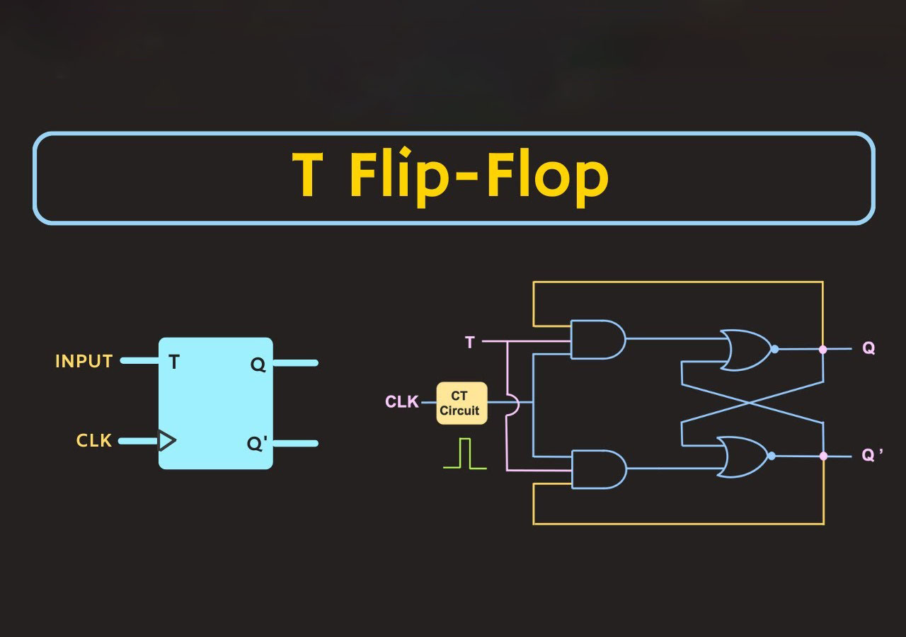
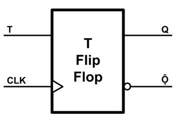
The main purpose of T Flip-Flop is to avoid the occurrence of the intermediate state in SR Flip-Flop. The following figure shows the logic symbol of the T flip–flop. It has one Toggle input (T) & one clock signal input (CLK).
You can build a T Flip-Flop from the other types of Flip-Flops, or by using logic gates as indicated by the below methods:
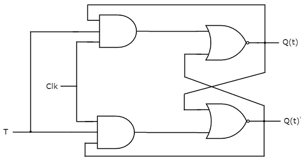
1) Using 2 AND, 2 NOR Gates
In this application, we need two AND gates connected to two NOR gates. Each AND gate needs 3 wires; a common toggle input (T), a common clock signal (CLK), and a feedback wire from the present state output (Q) or its complement (Q'). Then connect these AND gates as inputs for the NOR gates with a wire from the other NOR gate output. The following figure represents this method:
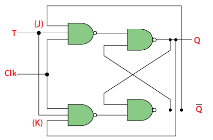
2) Using 4 NAND Gates
This method uses 4 NAND gates and is similar to the method described above. Two gates will be connected to the inputs and two with the outputs. Each input gate also has three input wires; toggle input (T), a common clock signal (CLK), and a cross feedback wire from the state output. Those gates form the input for the other ones with cross feedback from the output as shown in the figure:
T Flip-Flop could be a positive or negative edge-triggered device. In other words, the inputs will affect the output only when the clock signal changes from low to high for positive, or from high to low for negative. However, when an edge applied to the clock input, the Flip-Flop will hold or latch the last output (Q) if T=0, and will toggle it to its complement if T=1.
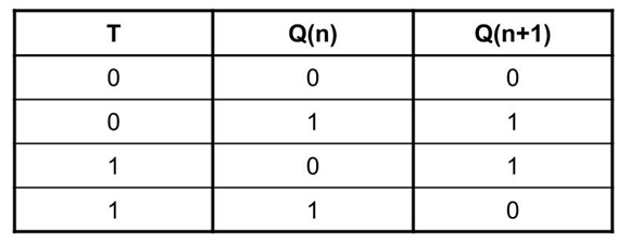
Below you can find the truth table for T Flip-Flop:
We can find T Flip-Flop in many applications, mainly in frequency dividers, binary counters, and parallel load registers. To build a frequency divider you will need two T Flip-Flop electronic parts. Connect their toggle inputs to high "1", then connect the output of the first Flip-Flop as a clock for the other one. The final output will be half the frequency of the main clock, and those outputs can be used also as binary counter bits. If you need to use the T Flip-Flop in your circuit you may not find an IC that implements it, but you can use a JK Flip-Flop IC (i.e., 74107 or 7476) and short both J and K inputs together to make it a single T input.
The Internal Structure of a T Flip-Flop
A T Flip-Flop is typically built using logic gates, such as NAND gates, NOR gates, or even more advanced configurations like SR (Set-Reset) Flip-Flops. The core functionality of the T Flip-Flop revolves around its input (T), its clock signal (CLK), and its outputs (Q and Q’).
Here’s a simple breakdown of the core components:
• T Input (Toggle): The 'T' input controls whether the flip-flop will toggle its state. When T = 1, the flip-flop will toggle between states on every clock pulse. When T = 0, the flip-flop retains its current state regardless of the clock signal.
• Clock (CLK): Like all flip-flops, the T Flip-Flop is edge-triggered, meaning it only changes state on specific transitions of the clock signal, usually on the rising edge (low to high transition) or falling edge (high to low transition).
• Outputs (Q and Q’): The output Q represents the current state of the flip-flop, while Q’ (or Q-bar) represents the complementary state. These outputs are used to store binary data.
Truth Table of the T Flip-Flop
The behavior of the T Flip-Flop can be summarized using a truth table, which outlines the relationship between the inputs and the outputs. Here's the truth table for a T Flip-Flop:
| T (Input) | Clock Edge | Q (Output) | Q' (Output) |
|---|---|---|---|
| 0 | ↑↓ | No Change | No Change |
| 1 | ↑↓ | Toggle | Toggle |
T = 0: When the input T is 0, the output Q does not change, regardless of the clock pulse. The flip-flop retains its previous state.
T = 1: When the input T is 1, the flip-flop toggles its state on every clock pulse. If Q was 0, it becomes 1, and if Q was 1, it becomes 0.
How Does the T Flip-Flop Work?
To understand the T Flip-Flop’s operation more deeply, let’s break it down step by step:
• Initial State: At the beginning, the flip-flop is in either the set (Q = 1) or reset (Q = 0) state.
• Clock Pulse: When a clock pulse is received, the flip-flop checks the state of the T input.
If T = 0, the flip-flop will not change its state. The output Q remains the same.
If T = 1, the flip-flop will toggle its state. If Q = 0, it will change to Q = 1. If Q = 1, it will change to Q = 0.
• Continuous Operation: The T Flip-Flop continues to operate in this manner, either holding its state or toggling between 0 and 1 with every clock pulse, depending on the input T.
Applications of the T Flip-Flop
The T Flip-Flop has numerous applications in digital circuits. Its primary feature—toggling between two states—makes it useful in a variety of scenarios. Some of the most common applications include:
• Counters:
The T Flip-Flop is often used in binary counters, which count up or down in binary. By cascading multiple T Flip-Flops, you can create binary counters that count in a sequence (e.g., 000, 001, 010, etc.).
• Frequency Dividers:
The T Flip-Flop can divide the frequency of a clock signal by two. This makes it ideal for applications that require frequency division, such as clock generation circuits and pulse-width modulation (PWM) applications.
• State Machines:
In sequential logic circuits, the T Flip-Flop can be used to implement state machines that transition between different states based on inputs. It is particularly useful in designing circuits like digital watches, traffic light controllers, and more.
• Memory Elements:
Since the T Flip-Flop stores one bit of data, it can function as a basic memory element in a larger memory array. In this role, it can be used for data storage or buffering.
• Edge-Triggered Applications:
The T Flip-Flop’s edge-triggered nature makes it suitable for applications that require synchronization, such as synchronizing data between different parts of a circuit or preventing race conditions.
Advantages of the T Flip-Flop
The T Flip-Flop offers several advantages in digital designs:
• Simplicity: The T Flip-Flop is easy to understand and implement, making it a preferred choice for beginners and experts alike.
• Efficiency: It can perform both storage and toggling functions with minimal hardware, making it ideal for space and power-constrained applications.
• Versatility: The T Flip-Flop can be used in a wide range of applications, from simple counters to more complex state machine designs.
Conclusion
The T Flip-Flop may seem simple at first glance, but its ability to toggle between two states based on the clock signal makes it a vital component in many digital systems. By understanding how the T Flip-Flop works and where it can be used, engineers and designers can create more efficient and reliable digital circuits. Whether you're designing a counter, a frequency divider, or a state machine, the T Flip-Flop is a building block that can help make your designs both effective and straightforward.
Written by Icey Ye from AIChipLink.
AIChipLink, one of the fastest-growing global independent electronic component distributors in the world, offers millions of products from thousands of manufacturers. Whether you need assistance finding the right part or electronic components manufacturers for your design, you can contact us via phone, chat or e-mail. Our support team will answer your inquiries within 24 hours.


